solid-state relay
Source: InternetPublisher:5Y14k97 Keywords: solid-state relay Updated: 2026/02/11
solid-state relay
Solid-state relays are hybrid circuits, typically consisting of an optocoupler (isolates the input), a trigger circuit (detects zero-crossing of the line current), and a bidirectional thyristor or similar device (acting as a circuit breaker). Their name derives from their similarity to electromagnetic relays. These devices are generally used in applications requiring continuous use of the relay contacts. Compared to conventional relays, they exhibit significant mechanical wear and can switch high currents, whereas electromagnetic relays would quickly damage the contacts. These relays allow for switching speeds far exceeding those of electromagnetic relays.
Solid-state relays are being used more and more because of their advantages: no mechanical parts that eventually wear out, and these components are very interesting for many applications, built from semiconductors.
advantage:
No mechanical parts are prone to wear
Switching load only when voltage crosses zero
No electrical interference during switching.
Wide range voltage control
High isolation between control and load circuits
High mechanical strength
No noise during switching
All of this is good, but like most things, it has its drawbacks. Because the triac is connected to the power supply circuit, these components require a minimum load current (known as the holding current, 25-100mA) for the circuit to run smoothly. The triac also handles a small portion of residual current (7 mA in this circuit, which most manufacturers omit in their datasheets), meaning you can't get the complete power isolation that a regular relay contact provides.
characteristic:
Control voltage 3V to 30V DC
Output voltage 115V to 280V AC
Output power 400W (unmodified, with heatsink)
Minimum operating current 50 to 100mA
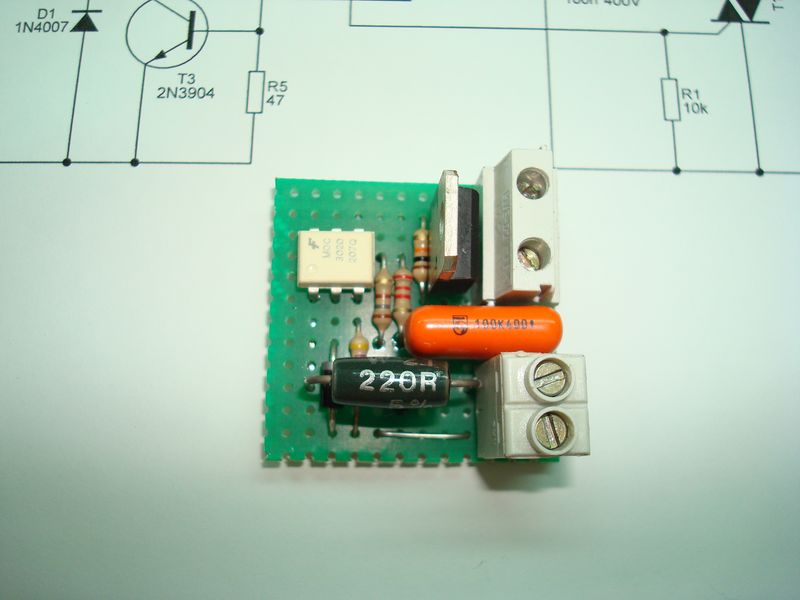
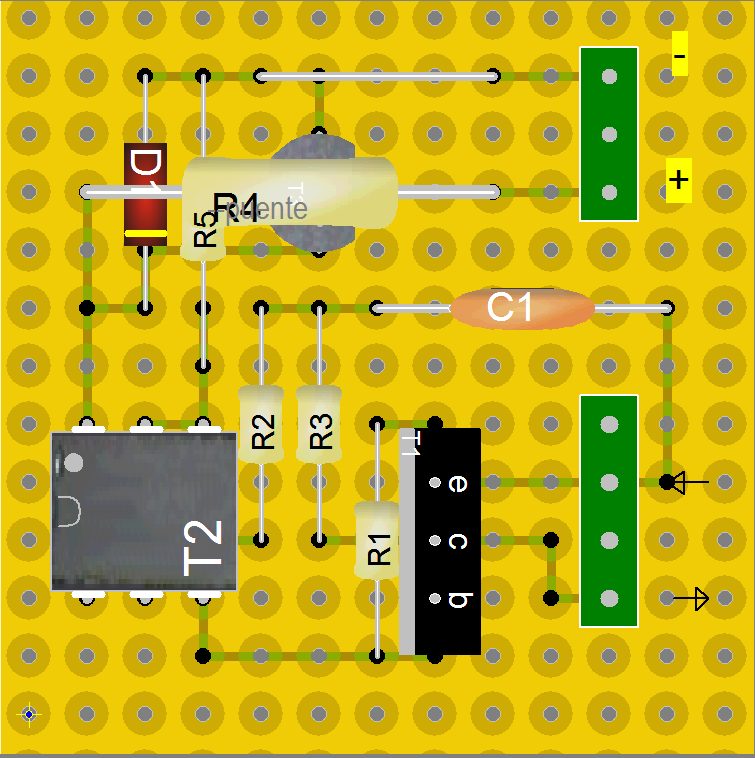
Connection Example
Component list
C1 = 100N 400V cc
D1 = 1N4007, 1N4004
R1 = 10k 1/4w
R2 = 180 1/4w
R3 = 2k2 1/4w
R4 = 220 2W
R5 = 47 1/4w
T1 = BTB-BTA 08-600 08-600
T2 = MOC3020, K3020
T3 = 2N3904


- Temperature-controlled fan
- DS18B20 Bluetooth Thermometer
- Resistive switch network audio volume control
- USB relay board
- Electronic fuses for DC short circuit protection
- Alternating forward and reverse motor driver
- wiper speed control circuit
- Countdown relay timer
- Making a Simple Temperature Controller Using Adjustable Electric Contact Mercury Thermometer
- A switch controls the start and stop circuit diagram
- Homemade disinfectant circuit
- Flashing wall light control circuit
- Photocell trigger control circuit
- Digital camera flash control circuit
- Car window control circuit
- PLC light source robot hand bubble control circuit
- The structure of Hisense KFR-25GW-06BP inverter air conditioner outdoor unit microprocessor control circuit
- Photoelectric output control circuit
- Relay control circuitb
- AC solid state relay controlled motor forward and reverse control circuit


 京公网安备 11010802033920号