PWM DC motor speed regulation circuit diagram composed of LM324
Source: InternetPublisher:无人共我 Keywords: Power switch voltage regulator Updated: 2020/09/21
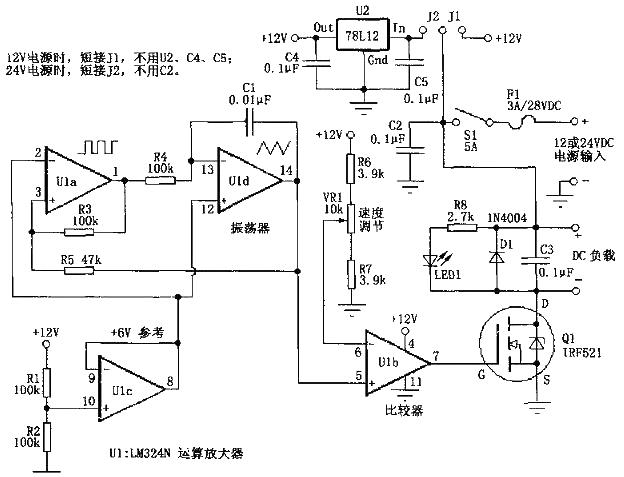
PWM DC motor speed regulation circuit diagram based on LM324
It mainly consists of U1 (LM324) and Q1.
In Figure 1, U1a and U1d form an oscillator circuit that provides a square/triangular wave with a frequency of about 400Hz. U1c generates a 6V reference voltage that serves as a virtual ground for the oscillator circuit. This is so that the oscillator circuit can work on a single power supply without using dual positive and negative power supplies. U1b is connected here in the form of a comparator, and its inverting input terminal (pin 6) is connected to resistors R6, R7 and VR1 to provide the reference voltage of the comparator. This voltage is compared with the triangular wave voltage at the output terminal of U1d (pin 14). When the waveform voltage is higher than the voltage of pin 6 of U1b. The output of pin 7 of U1b is high level; conversely, when the waveform voltage is lower than the voltage of pin 6 of U1b, the output of pin 7 of U1b is low level. From this we can know that the potential of pin 6 of U1b is changed to compare it with the input triangle wave voltage. You can increase or decrease the width of the output square wave to achieve pulse width modulation (PWM). Resistors R6 and R7 are used to control the end point of VR1 to ensure that when adjusting VR1, the output can be fully open (full speed or full brightness) or fully closed (stopped or completely off). The actual resistance value may vary according to the actual circuit. Different changes.
In Figure 1, Q1 is an N-channel field effect transistor, which is used as a power switch transistor (current amplification) to drive the load part. The square wave signals of different widths provided by the previous circuit control the on and off of Q1 through the gate (G). The brightness change of LED1 can be used to indicate the pulse width of the circuit output. C3 can improve the circuit output waveform and reduce the radio frequency interference (RFI) of the circuit. D1 is used to prevent the back electromotive force of the motor from damaging Q1.
When using a 24v power supply voltage, the circuit in Figure 1 converts 24V into 12V through U2 for use by the control circuit. Q1 can be directly connected to the 21v power supply. For Q1, this is no different from being connected to the 12v power supply. Referring to Figure 1, changing the connection of J1 and J2 can make the circuit work under different power supply voltages (12V or 24V). When the current through Q1 does not exceed 1A, Q1 does not need a heat sink. But if the current exceeds 1A when Q1 is working, a radiator needs to be installed. If a larger current (greater than 3A) is required, IRFZ34N, etc. can be used to replace Q1.
- The basic principles of power supply design. What are the key components of a power supply?
- How about the boost converter TPS61299?
- How to use a simple circuit to achieve a smooth soft-start for an isolated converter
- Cleverly use the electronic ballast of waste energy-saving lamps as power supply transformer
- Brief Analysis of the Working Principle of AC Voltage Stabilizer Circuit
- Basic circuit description of adjustable voltage regulator LM317
- Transformerless AC-DC constant current LED driver circuit
- Constant current LED lamp driver circuit with soft start and anti-shock
- Parallel DC regulated power supply circuit diagram
- USB power socket using the car battery
- STR5412 power circuit
- Power circuit of STR5412
- Industrial X-ray flaw detector delay control switch circuit diagram
- Fixed and switching hybrid regulated power supply electronic circuit diagram
- Schematic diagram of a sound and light dual control energy-saving switch circuit
- DC 12V to AC 100V inverter power supply circuit design
- 2-phase CPU power circuit using HIP6301 and HIP6601 chips
- 500A-6V single-phase thyristor voltage regulating electroplating power supply circuit
- Class A power amplifier power circuit
- Antenna amplifier synchronous power supply circuit


 京公网安备 11010802033920号