T flip-flop circuit structure and its input-output signal waveform
Source: InternetPublisher:aytwartoofyoroo Keywords: Trigger signal waveform output signal circuit structure Updated: 2020/11/29
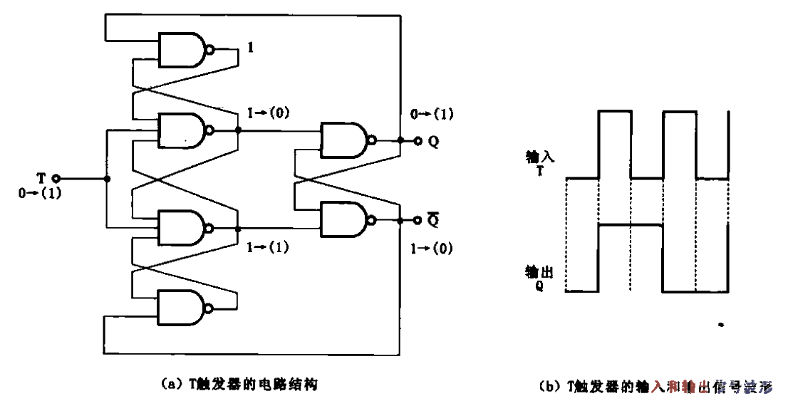
T flip-flop circuit structure and its input-output signal waveform
Latest Basic Circuits Circuits
- How are diodes made using semiconductors?
- An article explains the working principle of the Wheatstone bridge
- Analysis of the basic principle of measuring resistance by bridge method
- FPGA Features and Architecture
- Analysis of the working principle of CMOS/CCD image sensor
- Causes of PCB deformation How to prevent circuit board bending and warping
- Build a musical fountain using Arduino and sound sensor
- Make a flameless electronic candle using simple electronics and LEDs
- Experimental circuit based on 4040 binary adder counter
- LED Bicycle Lights
Popular Circuits
- Two simple street light automatic control circuit diagrams
- How to judge whether the thyristor is good or bad by triggering circuit
- Integrated circuit OCL power amplifier circuit
- Input and output circuit structure of MPD7500G
- Input and output circuit structure of MPD7500G b
- Circuit structure of CS5333 chip
- Circuit structure of JK flip-flop
- The basic circuit structure of a differential amplifier
- Bistable flip-flop circuit
- Frequency divider composed of counter and RS flip-flop


 京公网安备 11010802033920号