Project Description:
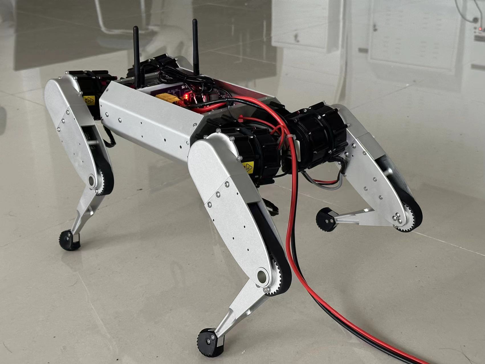
This project aims to independently develop a high-performance robotic dog capable of free movement in three-dimensional space. The robotic dog weighs 10kg, has an arm span of approximately 100cm, uses servo brushless motors to control joint movement, and achieves efficient control through CAN communication.
(This was done during my junior year of college; some details are still imperfect, so please be gentle with your criticism, I'm still a beginner. Also, please give it a like and save it!)

Connection Umbilical Cord Power Adjustment Diagram
Hardware Design
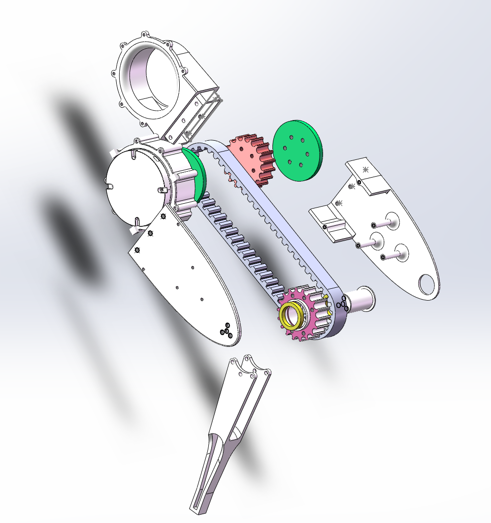
Power System: Each leg is equipped with three motors to ensure flexible leg movement in three-dimensional space. The knee joint motor uses a synchronous belt drive design to reduce energy loss during movement.
Control System:
Host Computer: Uses an NVIDIA Orin NX high-performance computer to support high-computing applications.
Slave Computer: Consists of two STM32H7 microcontrollers, which communicate with the host computer via SPI to parse instructions and control the motors.
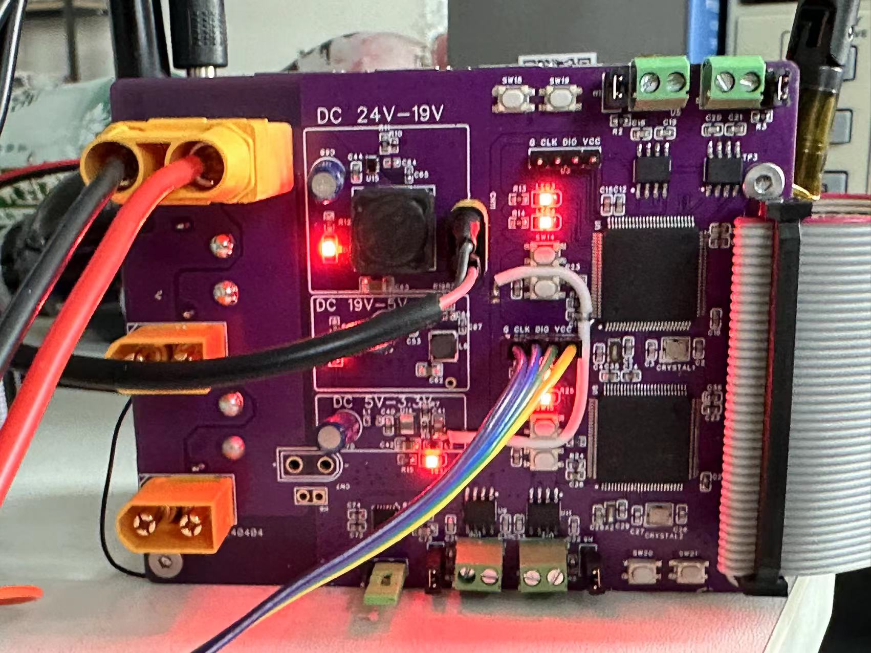
Power Management: Implements a three-way Buck switching step-down voltage regulator circuit with voltages of 24V-19V, 19V-5V, and 5V-3.3V, with load ripple below 30mV.
Communication: Four CAN buses achieve a communication rate of 1Mbps, and the SPI bus supports a speed of 16Mbps, ensuring efficient and stable data transmission.
Software System
Control Program: The host computer implements the underlying SPI transmission program and gait planning program, and a Xiaomi motor driver library has been developed, supporting control via ROS or C++.
IoT Integration: Sensor data from the robot dog is uploaded to an IoT platform via the MQTT protocol and displayed visually on the web, enhancing the user experience.
Mechanical Design
Component Design: A total of 79 components and 276 bolt holes (incomplete count) were designed, and the feasibility and stability of the design were ensured through over a hundred 3D printing verifications.
Material Selection: CNC-machined aluminum alloy parts are ultimately used for assembly, improving the structural strength and durability of the robot dog.
Open Source License
Open Source License Description
Project Related Functions
Main Configuration:
12 degrees of freedom, servo brushless joint motor (Xiaomi Micro Motor),
ORIN NX 16GB, onboard computer,
lower-level computer STM32H750
Functionality:
Several bionic gaits, general interface for adding LiDAR and depth camera
Project Attributes
This project is being publicly disclosed for the first time and is my original project. The project has not won any awards in other competitions.
System Architecture:
It mainly consists of a host computer, a slave computer, motors, and mechanical structures.
The slave computer system uses two STM32H7 chips and peripheral circuits to implement a three-level synchronous buck circuit, two SPI buses, and four CAN buses, each connected to 12 joint servo motors.
The slave computer communicates with the host computer using the SPI protocol at high speed to meet the requirements of high real-time and high-frequency motion control and attitude monitoring communication.
The host computer system consists of a JETSON-ORIN NX and external devices to realize attitude analysis and control, laser SLAM, environment modeling, autonomous motion, and navigation.
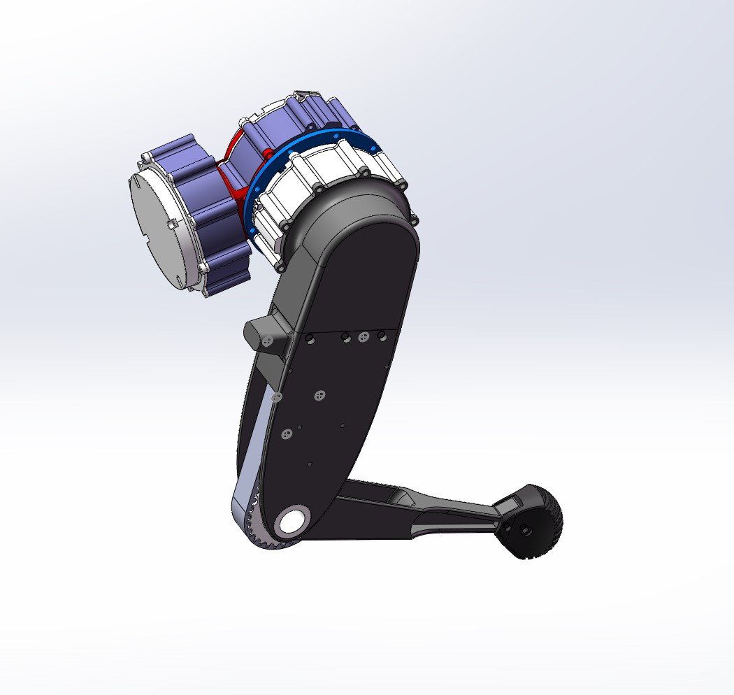
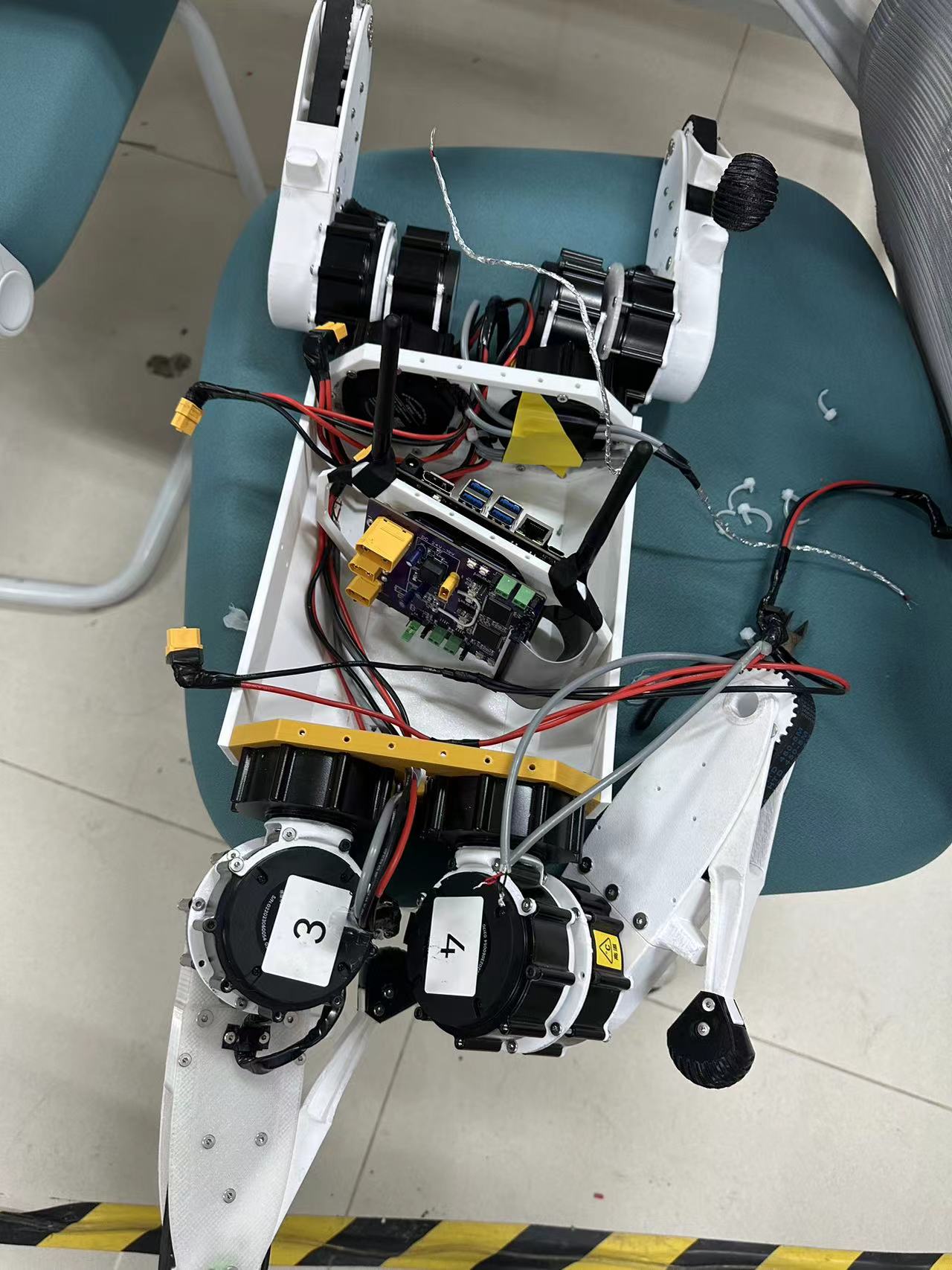
Mechanical Structure:
The mechanical structure consists of four mechanical legs, the robot body, and internal and external equipment mounting frames.
The design of the mechanical legs will be explained in detail below:
The mechanical legs consist of three joint motors and a transmission structure. The three joint motors are integrated at the hip joint through the transmission structure to reduce motion inertia.
The overall structure is shown in the following diagram:
Detailed structural BOOM diagram (this diagram is from the initial structure, but only some dimensions were modified later; the overall structure remains unchanged):
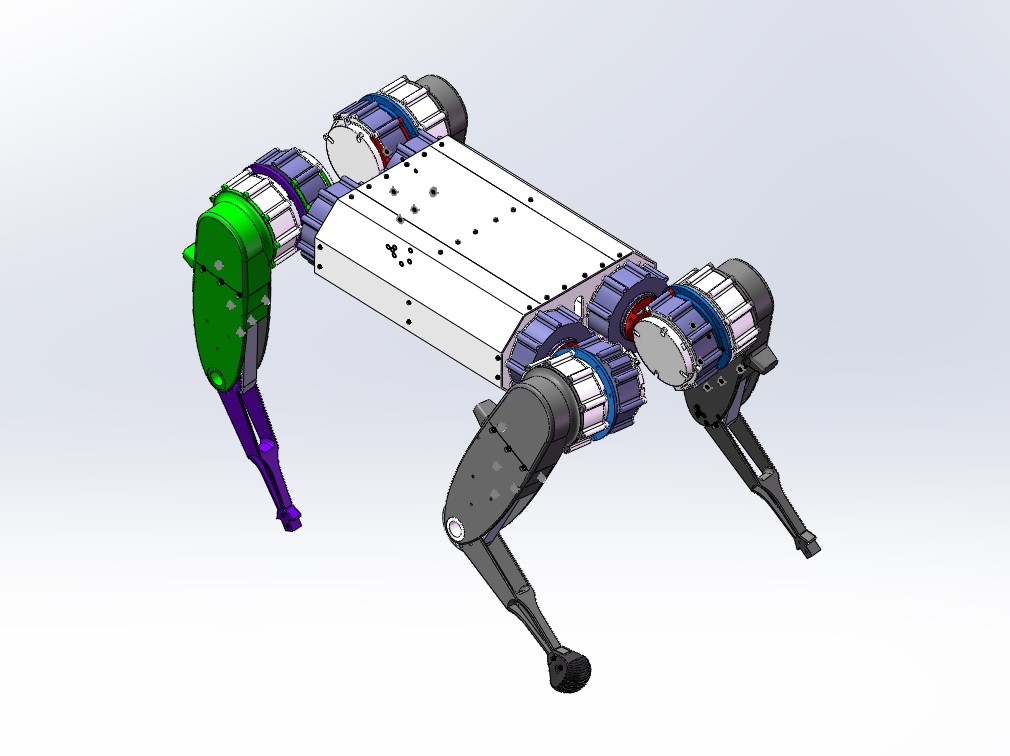
Overall structure diagram of the robot dog:
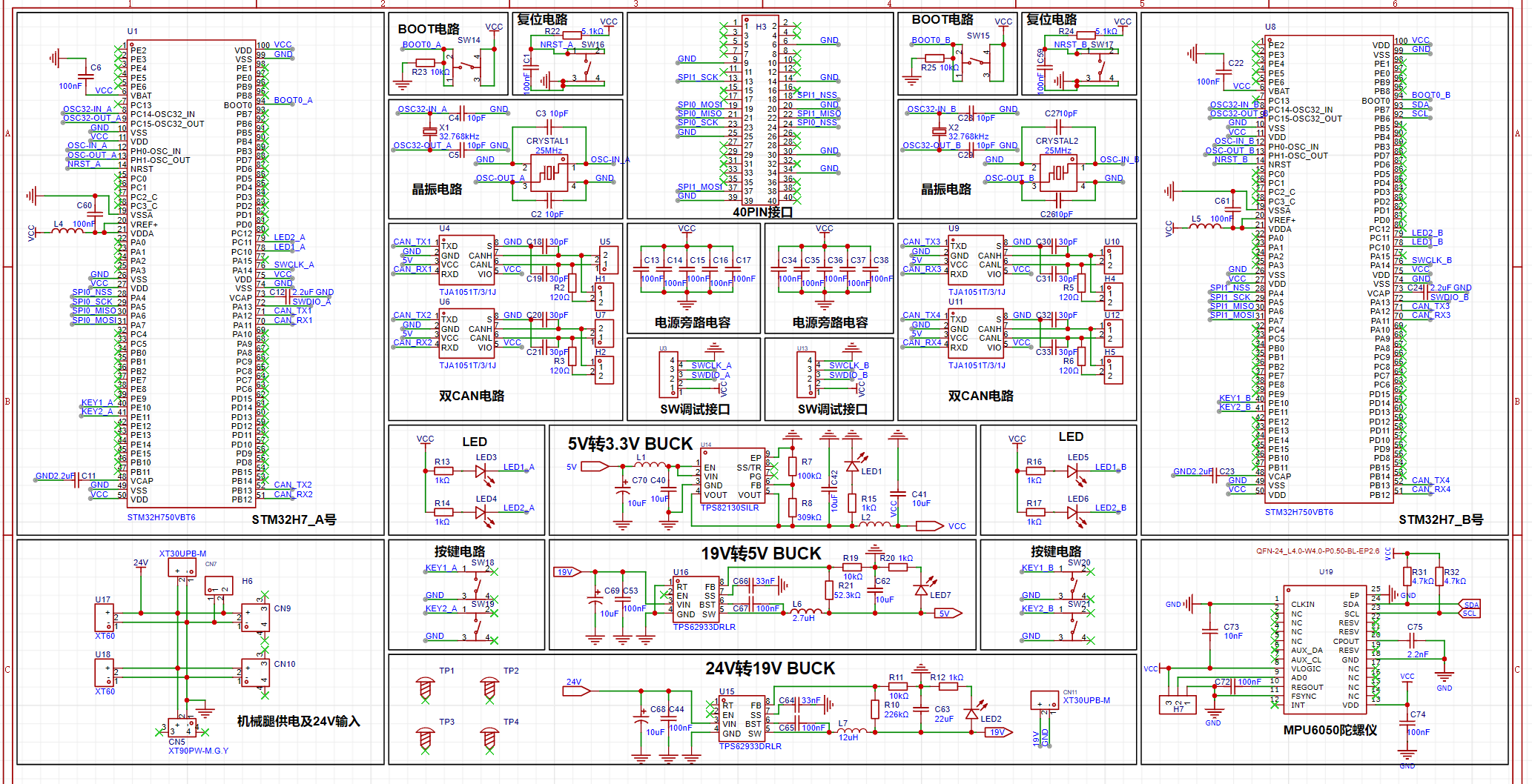
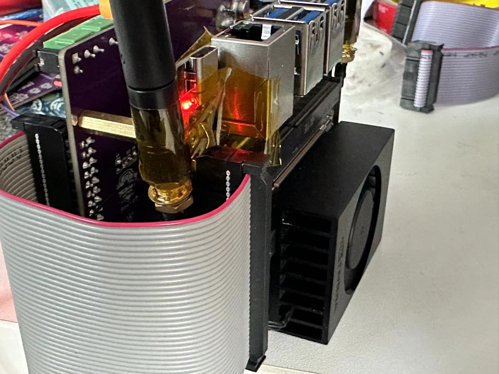
The lower-level system
connects to the upper-level system via a 40-pin ribbon cable and can be fixed to the upper-level system via M3 copper pillars . The main
controller consists of two STM32H750RCT6
microcontrollers with four CAN bus channels, each channel connecting three servo joint motors, for a total of 12 motors, with a maximum baud rate of 1MHz.
Two SPI channels are used for communication between each microcontroller and the upper-level system, with a maximum baud rate of 15MHz. An
onboard MPU6050 gyroscope and
three DC-DC synchronous step-down converters are provided: 24V-19V, 19V-5V, and 5V-3.3V. 19V powers the robot dog's upper-level ORIN NX (XT30), while 5V and 3.3V power the microcontroller system.
It also integrates a power distribution board, providing four 24V XT60 interfaces and one 24V XT30 interface. The
main components are shown in the figure.
Software
instructions: The software can use nested code blocks; no need to explain all software parts, just the important parts.
Physical demonstration :
Combined upper and lower computer diagram
, running and debugging diagram,
mechanical assembly diagram

. Dark crawling & tidy workbench:
Small steps, finally able to walk!!!

Plastic to iron, glue to welding, the complete form is here
! There are also unique marking postures!!!
Design considerations.
Other
mechanical files: I shared "Machine Dog Mechanical Files.rar" via Quark Cloud Drive. Link: https://pan.quark.cn/s/6a68fb8ff5b8
Microcontroller program: DOG_01, see attachment.
Upper computer program: DOG_CTRL, see attachment.


 京公网安备 11010802033920号

 BZX55C200AR1


