Preface:
While browsing Bilibili, I stumbled upon a mechanical quadruped made by a content creator, which inspired me to make a simplified version. Please excuse its simplicity.

Materials needed:
1. One STM32F103C8T6 development board

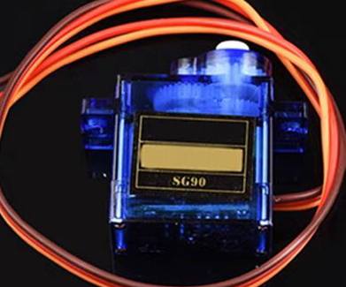
2. Eight blue SG9 classic 180-degree servos
3. One IIC communication OLED screen (large or small)

4. One 3.7V lithium battery + one 5V lithium battery Alternatively, you can use my lazy method: directly using the ST-Link power supply
schematic and PCB design instructions.
The design consists of four parts: power supply, OLED, servos, and STM32 board.
1. The power supply
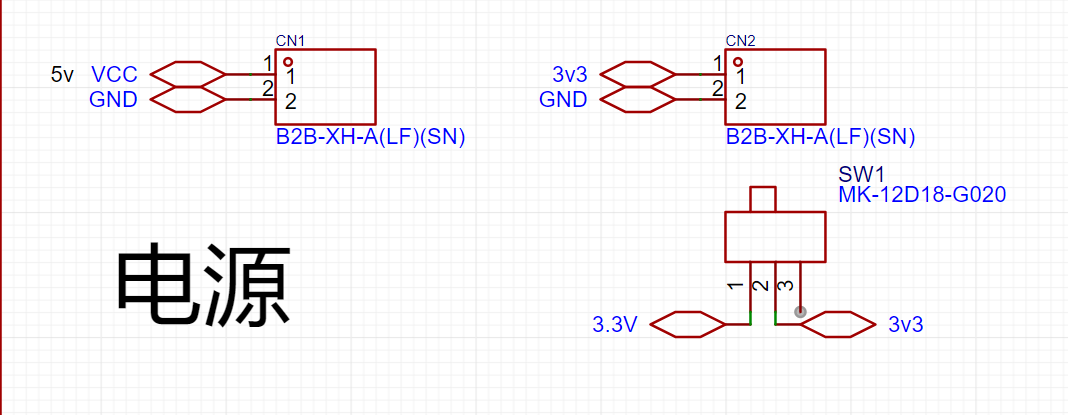
only requires a miniature toggle switch + two 2P headers or sockets. Alternatively, you can just place the pads and then connect the batteries with jumper wires.
Use the miniature toggle switch to control the power supply to the STM32 board.
The 3V power supply is for the STM32F103C8T6 board and can be powered by a small 3.7V lithium battery.
The 5V power supply is for the servos and can be powered by a 5V lithium battery.
Two batteries can be glued to the bottom of the base plate using a hot glue gun.
Of course, for lazy people like me, I can directly use the 3V3 and 5V drivers on the ST-Link, and I can modify the code at any time.

2. The I2C communication port of the OLED screen
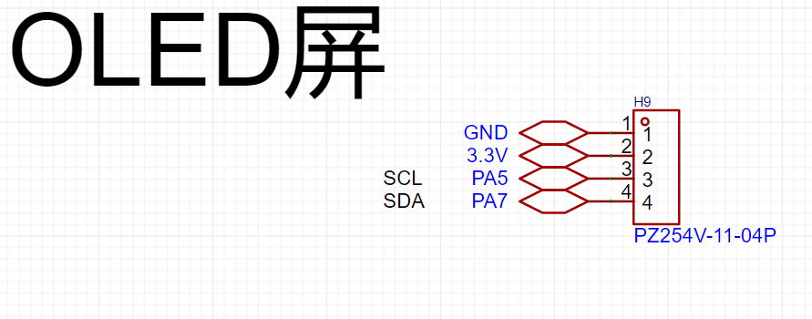
only needs a 4-pin header.
The screen I used here can be driven by 3V3, but you can also switch to 5V depending on the application.
The communication ports SC1 and SDA use PA5 and PA7 I/O ports respectively (this is how the code is written), and you can change them according to your own code.
If you are using other communication methods, this part needs to be modified accordingly.
3.
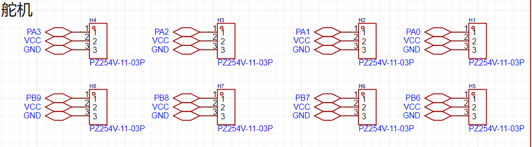
The reason for using these ports for the servo part is that the distance is short, and the subsequent wiring is simple.
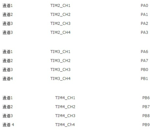
Secondly, when writing the code to control the servo, you need to consider the TIM clock. The following figure shows the I/O port corresponding to the TIM clock of the STM32. 4. For
the STM32F103C8T6
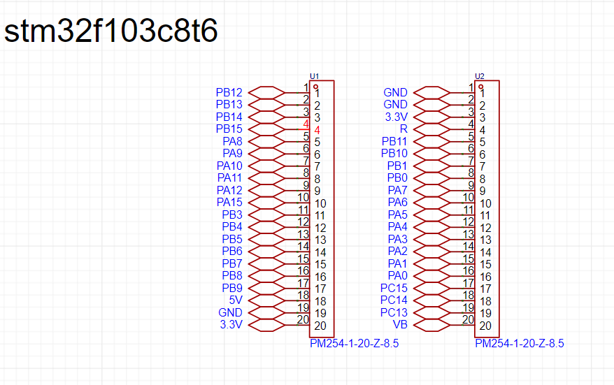
, I used female headers to draw each serial port of the STM32.
In the PCB, you need to pay attention to the spacing of the female headers, otherwise they will not fit.
The code section explains that
Keil 5 was used for programming. In fact, you only need to write the PWM file here. For OLED, you can just copy the header file that has been compiled online.
The PWM section
requires checking the STM32's TIM clock table.
I've chosen TIM2 and TIM4, so I need to define the I/O ports PA0, 1, 2, 3 and PB6, 7, 8, 9: `
void Pwm_Init_TIM2(void)
{
GPIO_InitTypeDef GPIO_InitTypeStruce
; TIM_TimeBaseInitTypeDef
TIM_TimeBaseInitTypeStruce;
TIM_OCInitTypeDef TIM_OCInitTypeStruce; RCC_APB2PeriphClockCmd(RCC_APB2Periph_GPIOA,ENABLE);//Enable the PA serial port and reuse the TIM2 clock
RCC_APB2PeriphClockCmd(RCC_APB2Periph_AFIO,ENABLE);
RCC_APB1PeriphClockCmd(RCC_APB1Periph_TIM2,ENABLE);`
GPIO_InitTypeStruce.GPIO_Mode=GPIO_Mode_AF_PP; // Set push-pull output
GPIO_InitTypeStruce.GPIO_Pin=GPIO_Pin_0|GPIO_Pin_1|GPIO_Pin_2|GPIO_Pin_3; // Define PA0, PA1, PA2, PA3 serial ports
GPIO_InitTypeStruce.GPIO_Speed=GPIO_Speed_50MHz;
TIM_TimeBaseInitTypeStruce.TIM_Period=1999; // The PWM period should be 20ms = (720*2000)/72000000=0.02
TIM_TimeBaseInitTypeStruce.TIM_Prescaler=719; // So I take the values 2000-1 and 720-1 respectively
TIM_TimeBaseInitTypeStruce.TIM_ClockDivision=0;
TIM_TimeBaseInitTypeStruce.TIM_CounterMode=TIM_CounterMode_Up;
TIM_OCInitTypeStruce.TIM_OCMode=TIM_OCMode_PWM1; //This sets the PWM mode.
TIM_OCInitTypeStruce.TIM_OutputState=TIM_OutputState_Enable;
TIM_OCInitTypeStruce.TIM_OCPolarity=TIM_OCPolarity_High;
GPIO_Init(GPIOA,&GPIO_InitTypeStruce); //The following initializes the four serial ports.
TIM_TimeBaseInit(TIM2,&TIM_TimeBaseInitTypeStruce);
TIM_OC1Init(TIM2,&TIM_OCInitTypeStruce);
TIM_OC2Init(TIM2,&TIM_OCInitTypeStruce);
TIM_OC3Init(TIM2,&TIM_OCInitTypeStruce);
TIM_OC4Init(TIM2,&TIM_OCInitTypeStruce);
TIM_OC1PreloadConfig(TIM2,TIM_OCPreload_Enable); // The following enables the clock for TIM2:
TIM_OC2PreloadConfig(TIM2,TIM_OCPreload_Enable);
TIM_OC3PreloadConfig(TIM2,TIM_OCPreload_Enable);
TIM_OC4PreloadConfig(TIM2,TIM_OCPreload_Enable);
TIM_Cmd(TIM2,ENABLE);
}
void Pwm_Init_TIM4(void) //TIM4 is similar to TIM2 in its settings, but GPIOA should be changed to GPIOB, TIM2 to TIM4, and the four serial ports should also be modified
{
GPIO_InitTypeDef GPIO_InitTypeStruce;
TIM_TimeBaseInitTypeDef TIM_TimeBaseInitTypeStruce;
TIM_OCInitTypeDef TIM_OCInitTypeStruce;
RCC_APB2PeriphClockCmd(RCC_APB2Periph_GPIOB,ENABLE);
RCC_APB2PeriphClockCmd(RCC_APB2Periph_AFIO,ENABLE);
RCC_APB1PeriphClockCmd(RCC_APB1Periph_TIM4,ENABLE);
GPIO_InitTypeStruce.GPIO_Mode=GPIO_Mode_AF_PP;
GPIO_InitTypeStruce.GPIO_Pin=GPIO_Pin_6|GPIO_Pin_7|GPIO_Pin_8|GPIO_Pin_9;
GPIO_InitTypeStruce.GPIO_Speed=GPIO_Speed_50MHz;
TIM_TimeBaseInitTypeStruce.TIM_Period=1999;
TIM_TimeBaseInitTypeStruce.TIM_Prescaler=719;
TIM_TimeBaseInitTypeStruce.TIM_ClockDivision=0;
TIM_TimeBaseInitTypeStruce.TIM_CounterMode=TIM_CounterMode_Up;
TIM_OCInitTypeStruce.TIM_OCMode=TIM_OCMode_PWM1;
TIM_OCInitTypeStruce.TIM_OutputState=TIM_OutputState_Enable;
TIM_OCInitTypeStruce.TIM_OCPolarity=TIM_OCPolarity_High;
GPIO_Init(GPIOB,&GPIO_InitTypeStruce);
TIM_TimeBaseInit(TIM4,&TIM_TimeBaseInitTypeStruce);
TIM_OC1Init(TIM4,&TIM_OCInitTypeStruce);
TIM_OC2Init(TIM4,&TIM_OCInitTypeStruce);
TIM_OC3Init(TIM4,&TIM_OCInitTypeStruce);
TIM_OC4Init(TIM4,&TIM_OCInitTypeStruce);
TIM_OC1PreloadConfig(TIM4,TIM_OCPreload_Enable);
TIM_OC2PreloadConfig(TIM4,TIM_OCPreload_Enable);
TIM_OC3PreloadConfig(TIM4,TIM_OCPreload_Enable); After writing the PWM initialization file, we can use the following functions for duty cycle control:
TIM_OC4PreloadConfig(TIM4,TIM_OCPreload_Enable); TIM_Cmd ( TIM4,ENABLE)
;
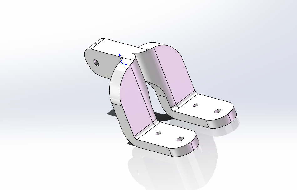
} Similarly, we still rely on the TIM clock , e.g.: TIM_SetCompare3(TIM2,50); // This means that the third serial port on the TIM2 clock (see the TIM clock table above), PA2, controls the servo to rotate to the 0° position. TIM_SetCompare2(TIM4,250); // This means that the second serial port on the TIM4 clock (see the TIM clock table above), PB7, controls the servo to rotate to the 180° position. Here, 50 corresponds to the servo rotating to 0°, and 250 corresponds to the servo rotating to 180° , which means that the rotation degree of the servo can be controlled between 50 and 250. For information on using the OLED part, please refer to CSDN for usage instructions. Master the OLED display principle – Learn various OLED module usage methods_OLED Usage Methods - CSDN Blog. Modeling instructions and parameters: I used SolidWorks 2022. Servo hole size: After 3D printing, the material extrusion allows for direct use of 2mm screws. Foot hole size: Also, 2mm screws are sufficient. Leg connection: Because mirroring was used, some cutting is required when slicing. Installation precautions: You need to know the three servo wires: Yellow or orange is the signal wire, red is the power wire, and black or brown is the ground wire. First, you need to know how the servo rotates:


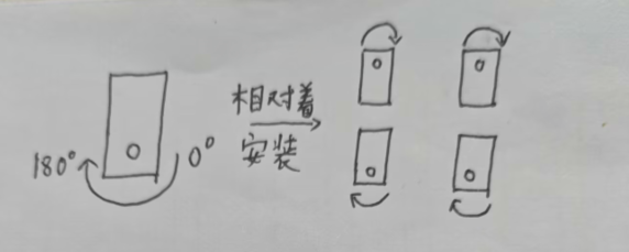
Before installation, you need to use code to rotate all the servos to 90° before fixing the legs. This increases the leg's freedom of movement.
First, use these codes:
`TIM_SetCompare1(TIM2,150);
TIM_SetCompare2(TIM2,150);
TIM_SetCompare3(TIM2,150);
TIM_SetCompare4(TIM2,150);
TIM_SetCompare1(TIM4,150);
TIM_SetCompare2(TIM4,150);
TIM_SetCompare3(TIM4,150);
TIM_SetCompare4(TIM4,150);`
to adjust the servos to 90°. Then connect the legs as shown in the diagram.
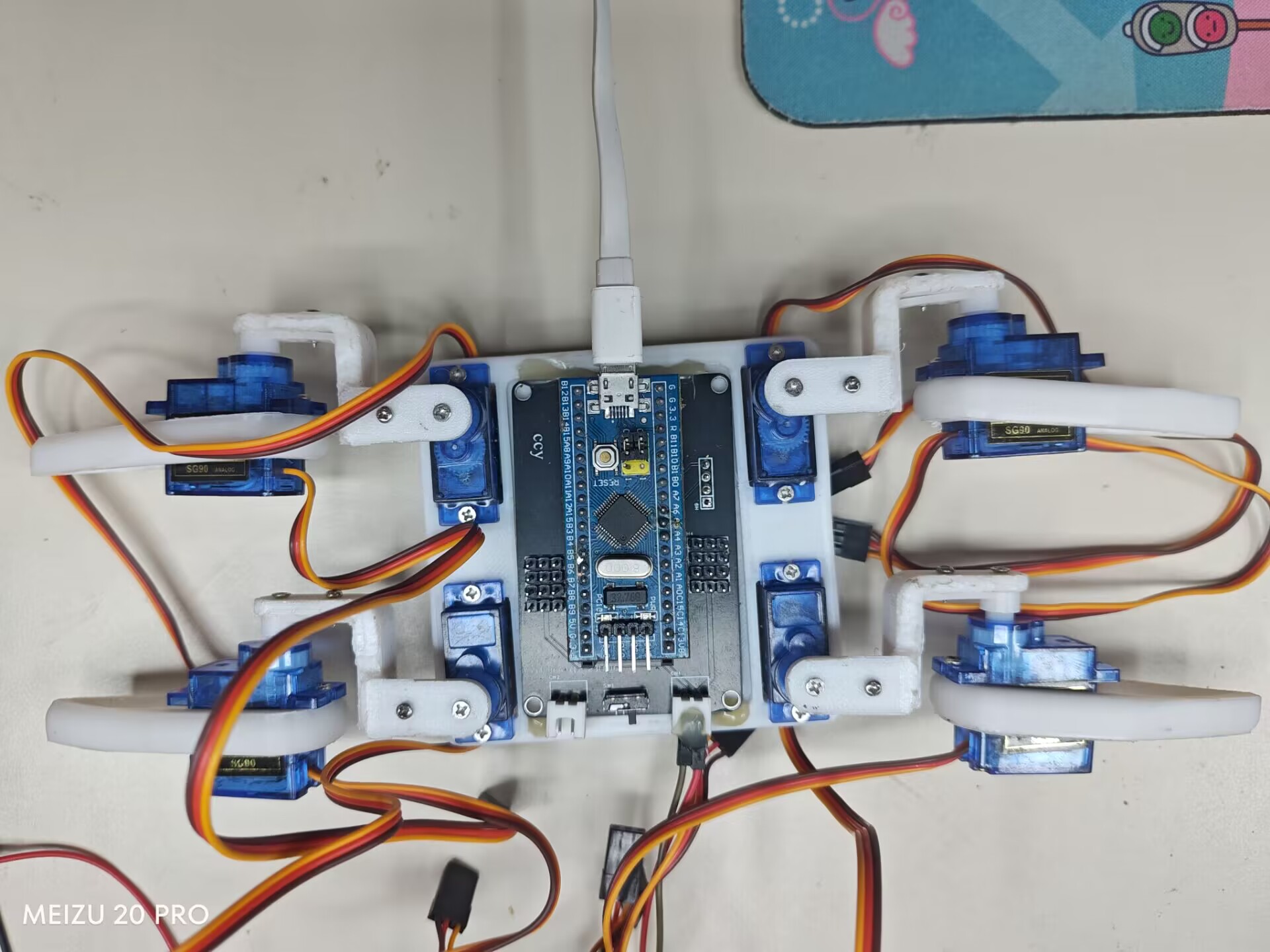
To run my code, connect the servo cables as shown in the diagram.

In summary
, since I'm still a university beginner, this is a very simple design. Please point out any problems. Thank you.


 京公网安备 11010802033920号

 150-90-306-00-001


