This project is based on https://oshwhub.com/Southerly/stm32f103zet6-hu-xin-ban and has been modified
without altering the original schematic. Only the PCB layout has been modified. The schematic is for reference only;
the BOM list should be based on the PCB layout. Do not use the BOM list in the project description directly!

Onboard functions include:
CAN interface, LCD interface, ATK module interface,
AD/DA interface, wireless module interface, OLED/camera interface,
TF card interface, three buttons, potentiometer replacing the photosensitive sensor,
SPI FLASH, USB Slave, and two LEDs.
Compared to the Zhengdian Atomic Elite Edition, some
RS485 modules,
infrared receiver modules,
temperature and humidity sensors, and DH11 interfaces have been
removed.
All USB interfaces have been replaced with Type-C,
the JTAG interface with an SWD interface
, and the boot0 and boot1 pin headers have been replaced with toggle switches.
The SD card slot has been replaced with a TF card slot
, the crystal oscillator with a surface-mount package, and
the buzzer has been replaced with a 5030 package (the original author used a passive buzzer, while Zhengdian Atomic uses the original buzzer).
The photoresistor has been replaced with a potentiometer .
Modifications from the original author include:
the Type-C connector has been changed from surface-mount to pin-mount, greatly enhancing robustness;
the CC pin of the Type-C connector is pulled down to 5.1k, a boon for C2C users;
the 3.3V power supply has been changed from the original AMS1117 to a DC-DC step-down circuit, and the board has been converted to a single-sided board. Teppanyaki enthusiasts are ecstatic!
The battery has been replaced with a battery holder for easier battery replacement.
The layout and wiring have been slightly modified; components no longer obstruct pin
definitions, and component labels have been added for easier soldering. Located below the TF card slot/USB port/chip, the soldering neatly conceals the
components. During PCB fabrication, I didn't realize the original author used a passive buzzer, so I simply soldered a speaker on it for a more abstract design.
The tantalum capacitor is purely for HiFi; a ceramic capacitor would suffice.
PS: It's convenient to stack the two boards together with screws and nuts, which is both aesthetically pleasing and prevents short circuits.
Suddenly, I discovered that a 3.3V power supply trace below the CAN interface was automatically removed from the loop. The project has already been published and cannot be modified.
The following text is the original author's note:
Except for the buzzer program (I'm using a passive buzzer, while Zhengdian Atomic uses an active buzzer), all other peripheral programs can be used directly and run normally.
For the removed parts, you only need to connect the corresponding modules yourself; the wiring is relatively simple.
This design has been continuously optimized and is now in its third (final) version, which has been successfully verified. The optimizations are as follows:
1. Added diodes to the SWD interface to prevent reverse connection and circuit burnout.
2. Modified the USB-TTL download circuit, replacing the original CH340C with a CH340K for a smaller package.
3. Optimized the wiring, thickened the power lines, and modified and optimized the signal lines.
4. Fixed existing bugs
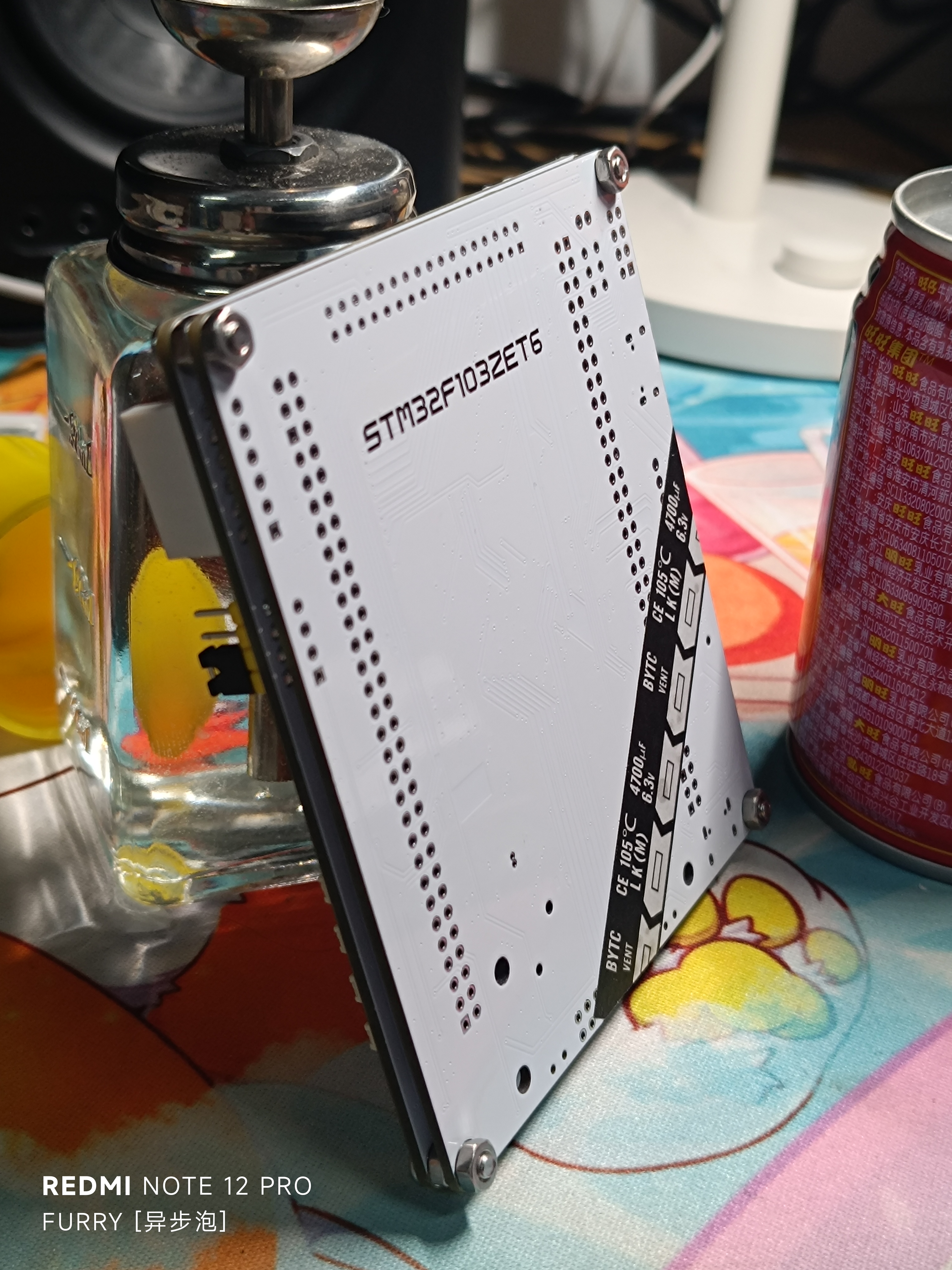
(ignore the adjacent Want Want milk).


 京公网安备 11010802033920号

 177-714-2-51GP6K5-24RDG


