Project Overview
: This project involves building a voltage and current meter based on the LCSC CW32F030C8T6 development board. It uses a 12VDC power supply and measures a maximum current and voltage of 3A and 30V respectively. The key advantages of the CW32 in this project are as follows:
Wide operating temperature range: -40 to 105℃;
Wide operating voltage range: 1.65V to 5.5V (STM32 only supports 3.3V systems);
Strong anti-interference: HBM ESD 8KV; All ESD reliability meets the highest international standard (STM32 ESD 2KV);
Project focus: Better ADC: 12-bit high-speed ADC with ±1.0LSB INL 11.3ENOB; Multiple Vref reference voltages (STM32 only supports VDD=Vref);
Stable and reliable eFLASH technology.
Hardware Design:
The hardware design consists of a DC power supply circuit, voltage and current sampling circuit, digital tube display circuit, LED indicator circuit, button control circuit, and a TL431 circuit design for voltage measurement calibration.
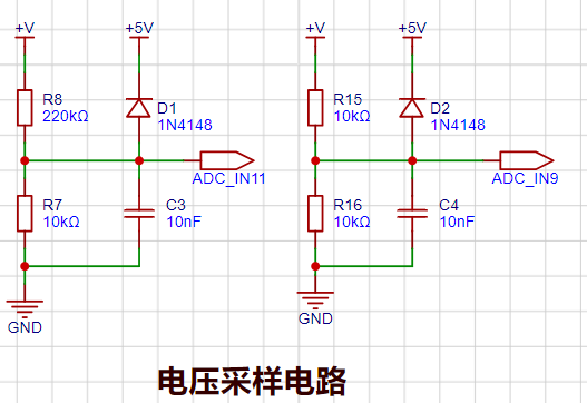
In this project, the voltage divider resistors are designed to be 220K+10K, resulting in a voltage division ratio of 22:1 (ADC_IN11). An additional voltage sampling circuit was added. By adjusting different ranges, the optimal measurement accuracy of the measured point within the corresponding range was obtained. When measuring voltages below 30V using the ADC_IN11 channel, if the measured voltage is within 0~3V, the ADC_IN9 channel is used. In this case, the measurement accuracy is greatly improved due to the reduced voltage division ratio.
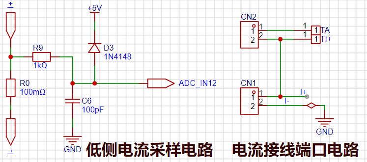
The sampling current designed for this project is 3A. Considering the need to select a larger sampling resistor to obtain a higher measured voltage for easier measurement, a 100mΩ sampling resistor (R0) was chosen. A low-side current sampling circuit is used for current detection, with the low-side of the sampling circuit sharing a common ground with the development board's meter interface. **

Important:
** Do not solder R0 during debugging. The
PCB
was fabricated using JLCPCB's color silkscreen printing process.
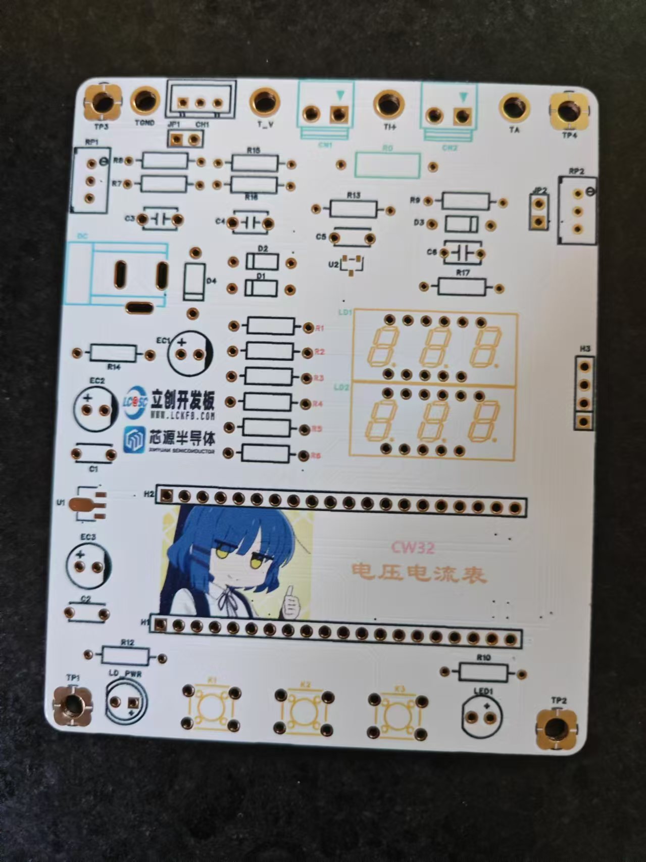

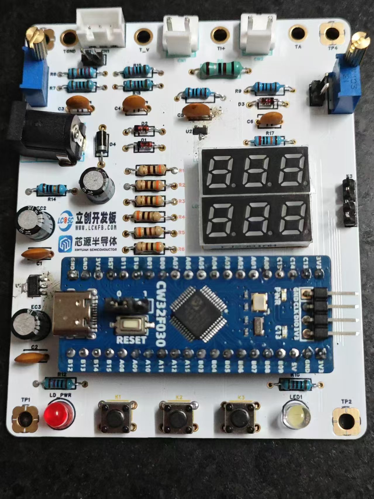
The components were soldered on, and the result is shown below.
Voltage and Ammeter.zip
BOM_Voltage and Current Meter CW32.xlsx
Voltage and Ammeter Project.zip
PDF_Voltmeter & Ammeter CW32.zip
Altium_Voltage and Ammeter CW32.zip
PADS_Voltage and Ammeter CW32.zip
92689
Diwenxing CW32 voltage and current meter
This is a voltage and current meter designed based on the LCSC Diwenxing development board, which can simultaneously measure 0-25V voltage and 0-3A current.
Project Overview:
This project designs a voltage and current meter based on the LCSC Divinstar development board, capable of simultaneously measuring 0-25V voltage and 0-3A current. Voltage measurement employs a resistor divider method, resulting in a simple and easy-to-implement circuit design. Current measurement utilizes an INA199 chip for signal amplification, improving measurement accuracy. The software employs a calibration algorithm to calibrate voltage and current, enhancing measurement precision.

Hardware Design:
1. Power Supply Circuit:
This project utilizes a DC 12V power input. An LDO is used to step down the DC 12V input to 5V for system power. For convenience, a Type-C power port is also added for direct 5V power supply.

Diodes are used for reverse connection protection, and resistor R1 prevents damage to the circuit due to excessive current; in case of excessive current, the resistor burns out, disconnecting the circuit. LED1 is the power indicator.
2. Voltage Sampling Circuit:
The voltage acquisition circuit uses two resistors to divide the input voltage. Since I usually use 0-24V, I used 10K and 100K resistors with a voltage ratio of 1:10. The microcontroller ADC reference voltage is 2.5V. The maximum voltage calculated using the formula is 27.5V, leaving a margin of 2.5V (25V). Therefore, the input voltage is set between 0-25V. A circuit with a 1:1 resistor ratio is also reserved for switching when measuring small voltages, improving measurement accuracy.

C5 and C6 are used for filtering, and two diodes are used to prevent damage to the microcontroller from excessive voltage.
3. Current Sampling Circuit:
The current sampling circuit uses a 0.01R resistor for sampling, then amplifies the current by 50 times using an INA199. The microcontroller ADC reference voltage is 2.5V. Calculations show that the maximum input current can reach 5A, and the INA199 supports bidirectional current acquisition. The schematic diagram includes R12 and a reference circuit. To achieve bidirectional current acquisition, R11 can be soldered while R12 is left unsoldered. Then, the reference voltage of the INA199 can be adjusted using a TL431 reference circuit to achieve bidirectional current measurement.

C8 is used for chip input power filtering, and D1 is a clamping diode; when the voltage exceeds 3.6V, it will be clamped at 3.6V to prevent damage to the microcontroller due to excessive input voltage.
4. Reference Circuit:
A reference circuit is provided, which can be used as the reference voltage for the microcontroller's ADC, or as the reference voltage for the INA199 when bidirectional circuit detection is desired. Using the TL431, the circuit is simple, easy to implement, and has good accuracy.

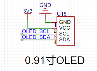
5. Display Circuit:
A 0.91-inch OLED with a resolution of 128*32 is used for display, which meets the usage requirements. The OLED communicates with the microcontroller using IIC, requiring only four wires, making it convenient to use.
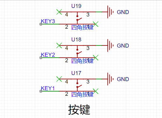
6. Button Circuit:
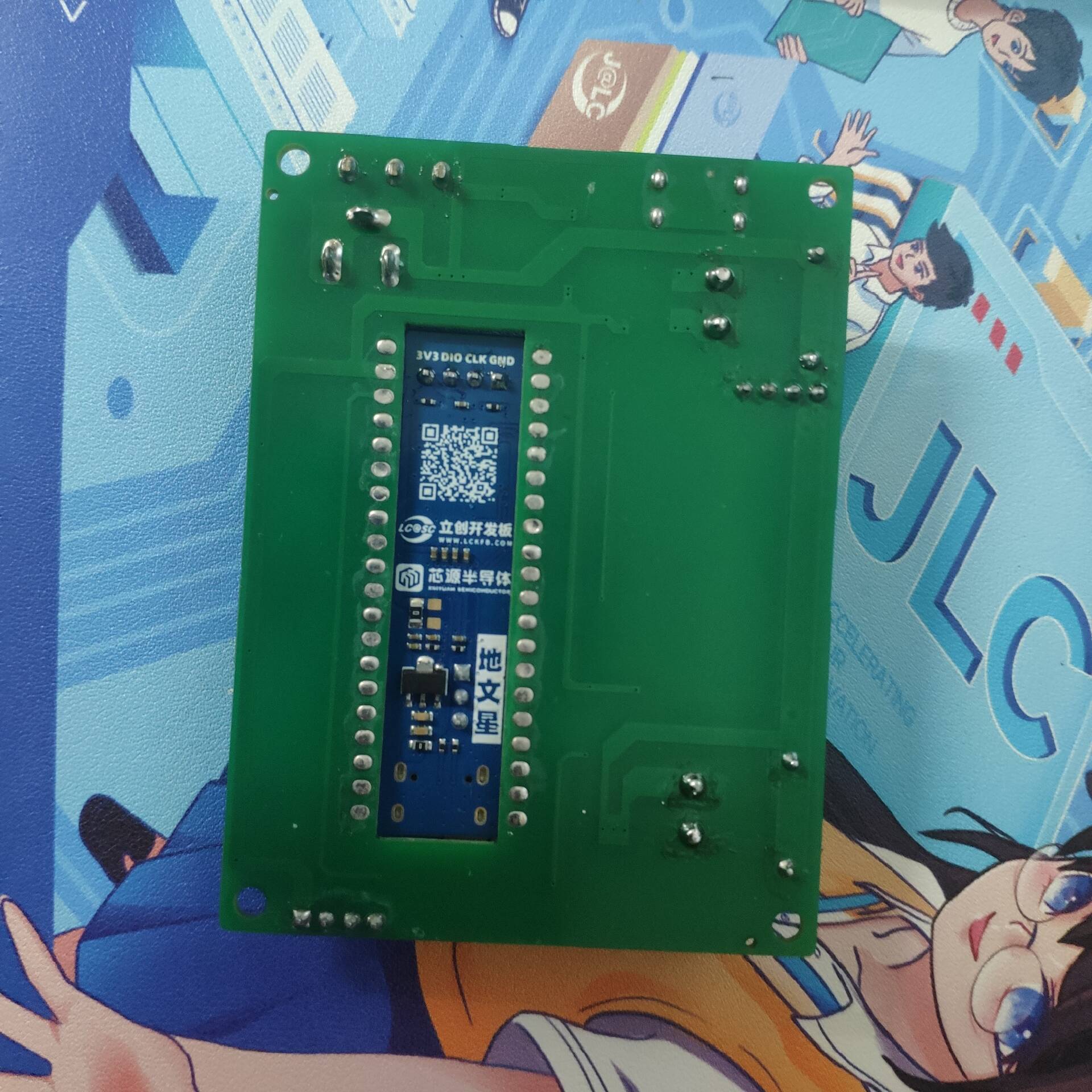
Three buttons are used for mode switching, calibration, and interface switching of the voltmeter and ammeter. 1. 3D model
of the actual product 2. Front view of the actual product 3. Back view of the actual product Instructions and demonstration video are included in the appendix. Demonstration video


Template.zip
Voltage Measurement and Calibration.mp4
Simultaneous voltage circuit measurement.mp4
PDF_Diwenxing CW32 Voltage and Current Meter.zip
Altium_地文星CW32 Voltage and Current Meter.zip
PADS_Diwenxing CW32 Voltage and Current Meter.zip
BOM_Diwenxing CW32 Voltage and Current Meter.xlsx
92690
12cm desktop adjustable fan
A spare 12cm cooling fan can be reused and transformed into a desktop fan.
For desktop
use, I found an adjustable 12cm fan bracket on MakerWorld, which works perfectly with this fan.
However, since the original design was for a bare fan without considering an additional PCB underneath, I raised the bracket to prevent the fan casing from extending beyond it.

The final result is shown in the image, and it feels quite good in use. The entire PCB was designed using LCSC EDA Professional Edition. After updating to version 2.2, the smoothness has finally improved significantly, making it much more comfortable to use. The overall circuit of the speed-
adjustable fan is very simple, consisting of a boost converter and PWM output. The boost converter chip used is the HX3608, and the PWM output uses the GP9101. Some points that might raise questions: The HX3608 boost feedback resistors use 16K and 1K resistors, resulting in an actual boost voltage of 10V. Driving a 12V fan shouldn't be a problem. The main reason is that I had a resistor of this ratio in stock on the potentiometer of the GP9101 input pin, connected in series with a 10K resistor. This is to prevent the fan from being too noisy when the potentiometer is turned to its maximum range and the PWM output is 100%. Therefore, I added a 10K resistor to limit the maximum PWM duty cycle to 66%. Two 5.1K resistors were added to ground the USB Type-C pin, which is standard practice for using a USB CC cable. PCB design: To ensure that the USB Type-C interface is close to the casing when the PCB is installed for easy connection of the charging cable, the overall PCB depth is designed to match the fan thickness. The fan thickness is 38mm, and the PCB is designed to be 35mm, allowing for a 2mm thickness allowance for the front and rear casings. However, after installation, it was found that the potentiometer was too far to the outside. It could actually be placed a little further in, so that part of the potentiometer cover could be hidden inside the casing, making the overall appearance more aesthetically pleasing.


12cm adjustable fan stand. 3mf
PDF_Desktop 12cm Adjustable Speed Fan.zip
Altium Desktop 12cm Adjustable Speed Fan.zip
PADS_Desktop 12cm Adjustable Speed Fan.zip
BOM_Desktop 12cm Speed Control Fan.xlsx
92692
Question 2024H: Autonomous Driving Car
The 2024 National Electronic Design Contest, Problem H, features an autonomous driving car. The main control chip is the M0 chip, and the design is modular.
Video Link:
Bilibili Video -- Function Demonstration and Introduction
This project is an autonomous driving car built using the TIM0 series chip as the main controller, employing an eight-channel grayscale sensor, a geared motor, and a TB6612 driver. It can automatically drive based on the input turning angle and has a line-following function.
This design is based on the TIM0 chip, and its main function is to automatically drive according to the set angle; it has four independent buttons, with functions including return, confirmation, increasing angle, and decreasing angle. There is an audio-visual prompt when switching between line-following driving and angle-based automatic driving.
This design uses a 0.96-inch OLED display with a three-level menu, allowing for four task selections. The buttons can change the set angle;
it is equipped with an HMC5883 electronic compass, which has a relatively accurate angle measurement function.
This project consists of the following parts: power supply, audio-visual function, main control, and electronic compass information acquisition. This project mainly uses the electronic compass to measure and process angles to control the automatic driving of the car.
Power Supply Circuit:
3S power supply is used, and STLink is directly used for downloading and debugging, without the need to convert to serial port signals.
LED sound and light circuit:
Uses through-hole LEDs and a passive buzzer as the sound and light prompt circuit, powered by 5V;
the main control section uses an M0 chip core board for data processing;
the electronic compass section is directly connected to the microcontroller pins for data transmission;
Note:
The car's angle needs to be set, and multiple tests are required.
TI.zip
9810650568e2295bf696025e08a5c965.mp4
PDF_2024H Question: Autonomous Driving Car.zip
Altium_2024H Problem: Autonomous Driving Car.zip
PADS_2024H Question: Autonomous Driving Car.zip
BOM_2024H Question: Autonomous Driving Car.xlsx
92693
51 Microcontroller Course Design—A Desktop Clock That Monitors Temperature and Humidity
Course Design Based on 51 Microcontroller
This system is an electronic clock system designed to monitor temperature and humidity parameters in real time using the AT89C52 microcontroller.
The system can monitor the ambient temperature and humidity in real time and display the data on a screen. It compares the data to upper temperature and humidity limits; if the limits are exceeded, a buzzer sounds and an LED flashes. The DS1302 microcontroller displays the real-time time on the screen, and a button switches to timer mode. A separate button sets the countdown, and the buzzer sounds when the countdown ends.
Using the 51 series microcontroller as the computing core, a simple system design can basically meet the system design requirements. The system should accurately display temperature and humidity data on an OLED screen, with a humidity limit of 70% and a temperature limit of 50%, triggering an alarm when these limits are exceeded.
PDF_51 Microcontroller Course Design—A Desktop Clock That Monitors Temperature and Humidity.zip
Altium_51 Microcontroller Course Design—A Desktop Clock That Monitors Temperature and Humidity.zip
PADS_51 Microcontroller Course Design - A Desktop Clock that Monitors Temperature and Humidity.zip
BOM_51 Microcontroller Course Design—A Desktop Clock That Monitors Temperature and Humidity.xlsx
92694
BMI088_SPI Small Board_2024
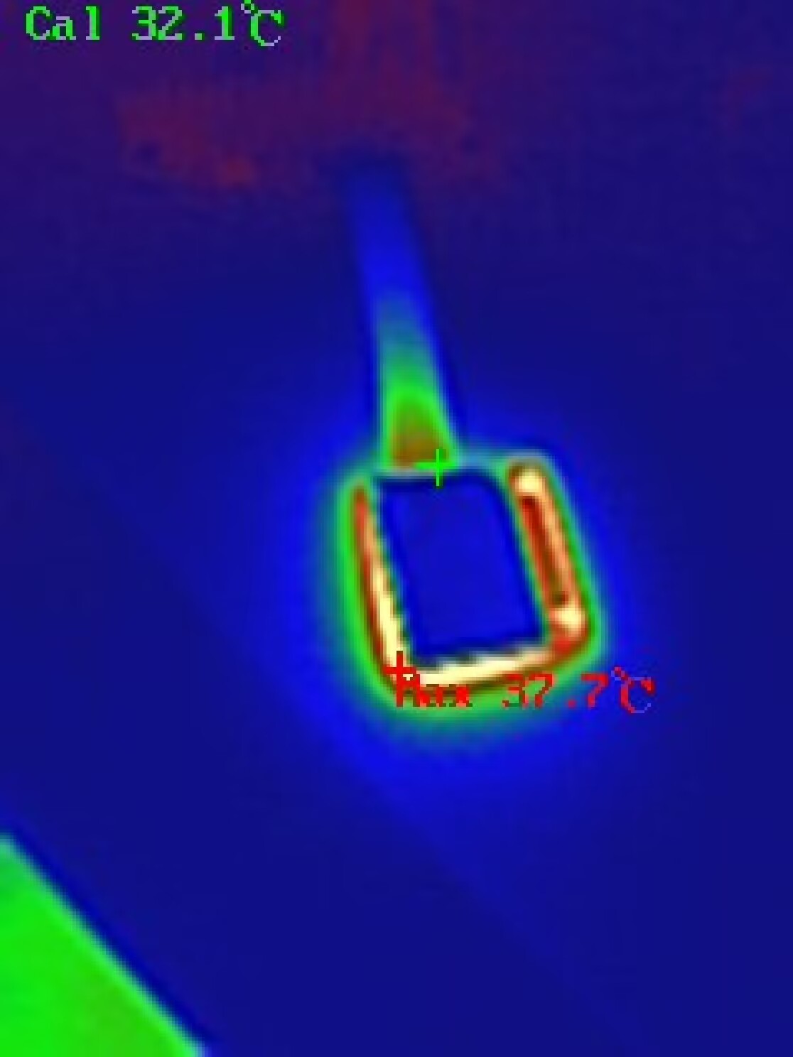
The BMI088_SPI board supports heating functionality to maintain a stable temperature.
The BMI088_SPI board supports heating functionality to maintain a stable temperature.
PDF_BMI088_SPI Small Board_2024.zip
Altium_BMI088_SPI small board_2024.zip
PADS_BMI088_SPI Small Board_2024.zip
BOM_BMI088_SPI Small Board_2024.xlsx
92695
[LCSC Training Camp] Building a Voltage and Current Meter Based on CW32
Participate in the [LCSC Training Camp] to learn and build a voltage and current meter based on CW32.
Participate in the LCSC training camp to build a voltage and current meter based on the CW32. The core board uses the domestic Wuhan Xinyuan Semiconductor CW32 as the main controller, and is also compatible with other similar development boards. After completion, it can be used as a desktop instrument.
1.1.mp4
CW Voltage and Current Meter Project.zip
PDF_【LCSC Training Camp】Building a Voltage and Current Meter Based on CW32.zip
Altium_【LCSC Training Camp】Building a Voltage and Current Meter Based on CW32.zip
PADS_【LCSC Training Camp】Building a Voltage and Current Meter Based on CW32.zip
BOM_【LCSC Training Camp】Building a Voltage and Current Meter Based on CW32.xlsx
92696
electronic


 京公网安备 11010802033920号

 105-316-48M-P30-B12


