LCSC Taishanpai Project Information Link: https://wiki.lckfb.com/zh-hans/tspi-rk3566/
A small mobile phone based on the LCSC Taishanpai project, using Rockchip RK3566 as the main control chip. The Taishanpai version is 2+16G. The system is Android.
: Using the Android system, it can access apps like a tablet, and includes a speaker and microphone. It uses the onboard Wi-Fi chip to connect to Wi-Fi.
: Screen Part: The purchased MIPI screen is inconsistent with the MIPI interface on the Taishanpai board, so an adapter circuit needs to be designed to ensure that the screen and its touchscreen can display and function normally. The screen backlight can be selected from the MIPI interface or the onboard boost circuit; it is recommended to use the onboard boost circuit.
Speaker and Microphone: Connected to the Taishanpai via spring-loaded pins.
Patch: Copy directly to the corresponding directory .
When soldering the joints with a soldering iron, be sure to secure them first.
shows a hole cut out for heat dissipation.
A WiFi weather clock and fan that can be used separately.
Project Overview: A
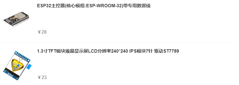
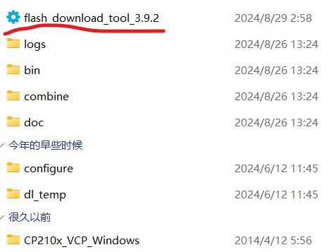
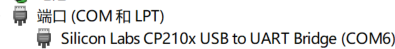
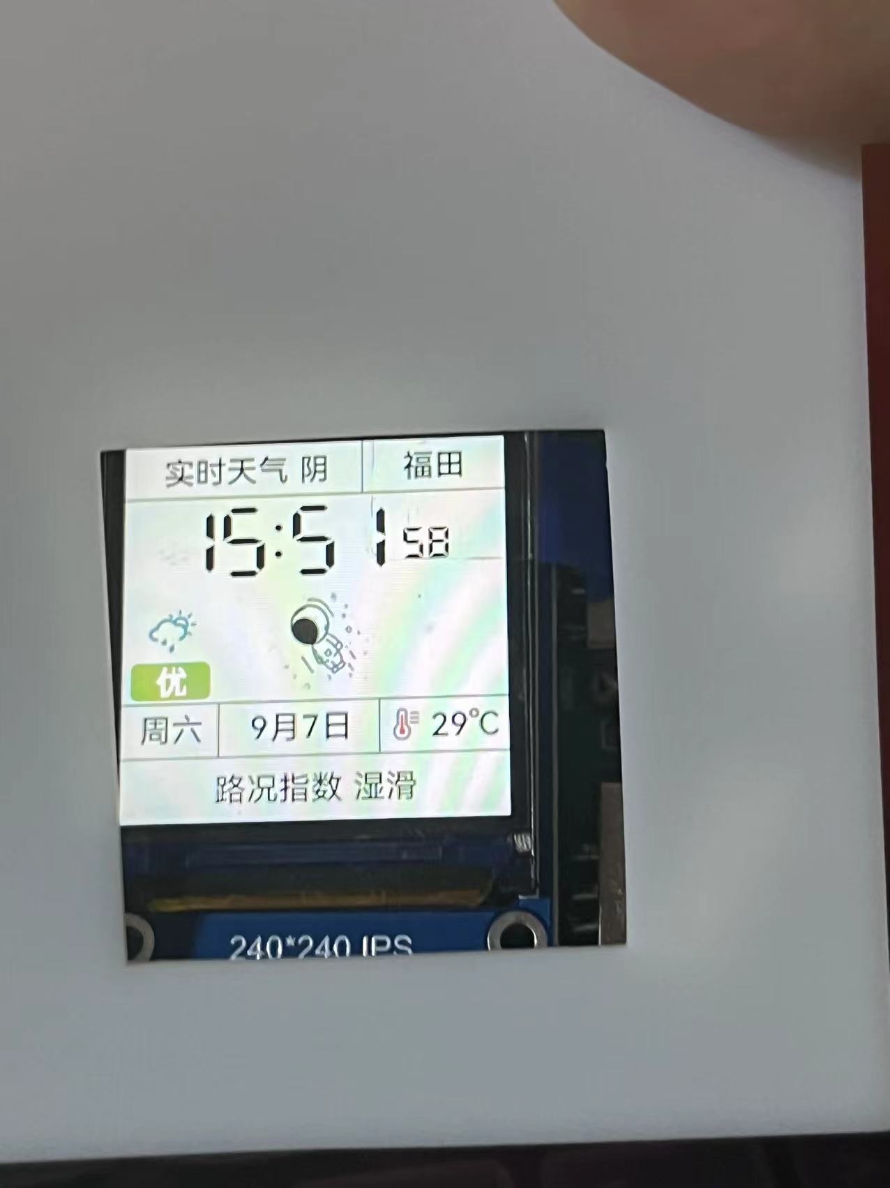
WiFi weather clock and fan that can be used independently. This design is based on the ESP32 microcontroller and includes a button for animation modification and network configuration. It displays time, weather, and temperature/humidity (outdoor). Pressing the button triggers a corresponding response. The fan speed can be adjusted using the included module. Project Parameters: This design uses an ESP32 development board, making coding easy. It features a 240*240 display screen: weather and region at the top, time in the middle, and weather quality, calendar, and temperature/humidity at the bottom. An adjustable mini turbine fan is used, allowing for speed adjustment to meet general needs. There are two corresponding expansion docks on each side, but for some reason, they cannot provide power. The expansion docks are referenced from other developers, but because the original projects cannot be found, they are not named. If the original author sees this, please message me for help. Please correct, thank you. Principle Analysis (Hardware Description): This section allows you to fill in the project's design principles, breaking down and analyzing the design principles. Example: This project consists of the following parts: pin header, power supply, and output. The pin header connects the screen to the ESP32 development board, enabling the screen to display... Purchase Link: Screen and Development Board: https://shop41675499.youzan.com/wscump/discount-packages?goodsId=3206076901&kdtId=41483331 Select these two turbine fans directly: The link provided is: https://item.taobao.com/item.htm?_u=720dsh6s006414&id=782589152199&spm=a1z09.2.0.0.2e2f2e8dSKSBeK. You can purchase the remaining items in the store . You can find similar products on Taobao. The software code ESP32 needs to be downloaded, and the driver needs to be found yourself; it's easy . The code is in the attachment. The specific tutorial is as follows: First, open this file shared via Baidu Cloud: Firmware Download (Recommended).rar. Link: https://pan.baidu.com/s/1D5WWveW3yNTsenrG0gHElA?pwd=dusi. Extraction code: dusi. Another recommended method is to use VS Code Platform.io. For the code, add me on QQ: 3596364883. (Because I don't have a membership for the cloud drive, I can only upload one file.) After opening, you'll find the extracted files. Open the extracted files, allow the first program to open, select ESP32, and click OK to enter this page. Open Device Manager, find the ESP32 port, select the port, and click START. After the burning process is complete, reconnect the power. Once successful, you'll see a network configuration mode. Connect to WiFi and enter network configuration mode. Enter your WiFi information, including your region data (in the attachment). After entering this information, the network will be automatically configured and the assembly process will begin. (Left screen, right fan - actual product image) . Since this is my first time working on a casing, the size may vary slightly. You can request a separate header. The docking station is not soldered.


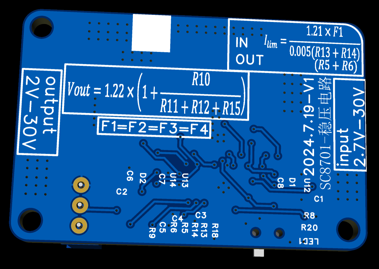
The output voltage can be adjusted with a potentiometer, and the input and output current limits can be adjusted by modifying the resistors. The PCB has complete calculation formulas, which can be ignored if current adjustment is not required.
This module is a DC-DC step-up/step-down power supply module. The output calculation method is clearly shown on the PCB. It can be used as a power supply for DC motors or as an adjustable power supply. My initial purpose in creating this module was for power supplies above 12V that drive brushless motors. A PD decoy module is connected to the input. When the plugged-in power supply supports the PD protocol, the input is 12V; when the power supply is only 5V, it can still be used for step-up. The 2A current limit also prevents power supply hiccups.
PDF_Based on Southchip SC8701 buck-boost module.zip
Altium_Based on Southchip SC8701 buck-boost module.zip
PADS_Based on Southchip SC8701 Buck-Boost Module.zip
BOM_Based on Southchip SC8701 buck-boost module.xlsx
92329
FT4232HPQ verification board
FT4232HPQ Verified Version
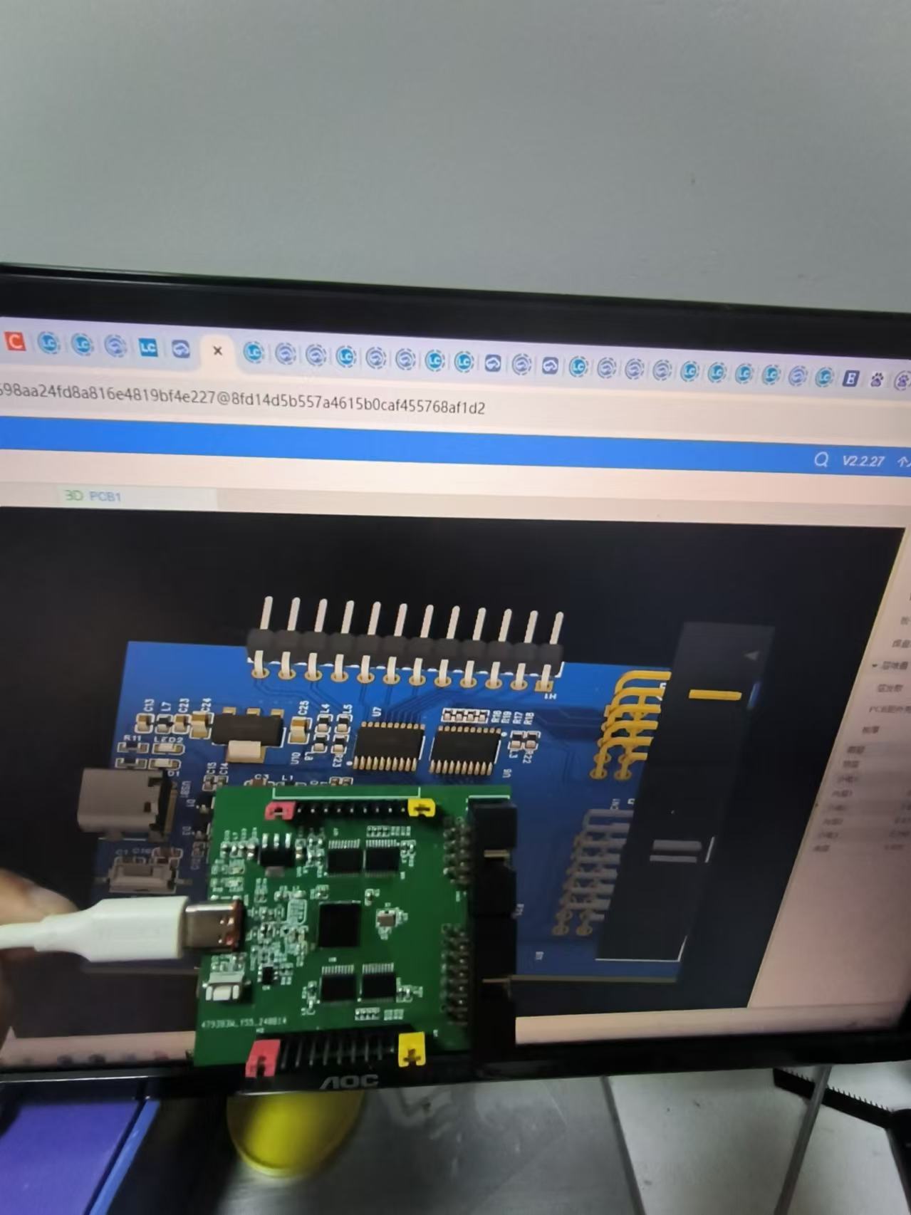
This project was originally intended for dual-channel JTAG + 2-channel UART + 1-channel IIC. The serial ports are currently being recognized correctly, and FT_PRO can also recognize the chip and EEPROM. However, when programming the JTAG using online tutorials, Vivado cannot be used for downloading.
Currently, it is being used with the default four-channel serial ports.
The hardware circuitry has no problems and can be directly prototyped.
6420958402782b4cd8d4444bd496695.jpg
PDF_FT4232HPQ Verification Board.zip
Altium_FT4232HPQ verification board.zip
PADS_FT4232HPQ verification board.zip
BOM_FT4232HPQ Verification Board.xlsx
92330
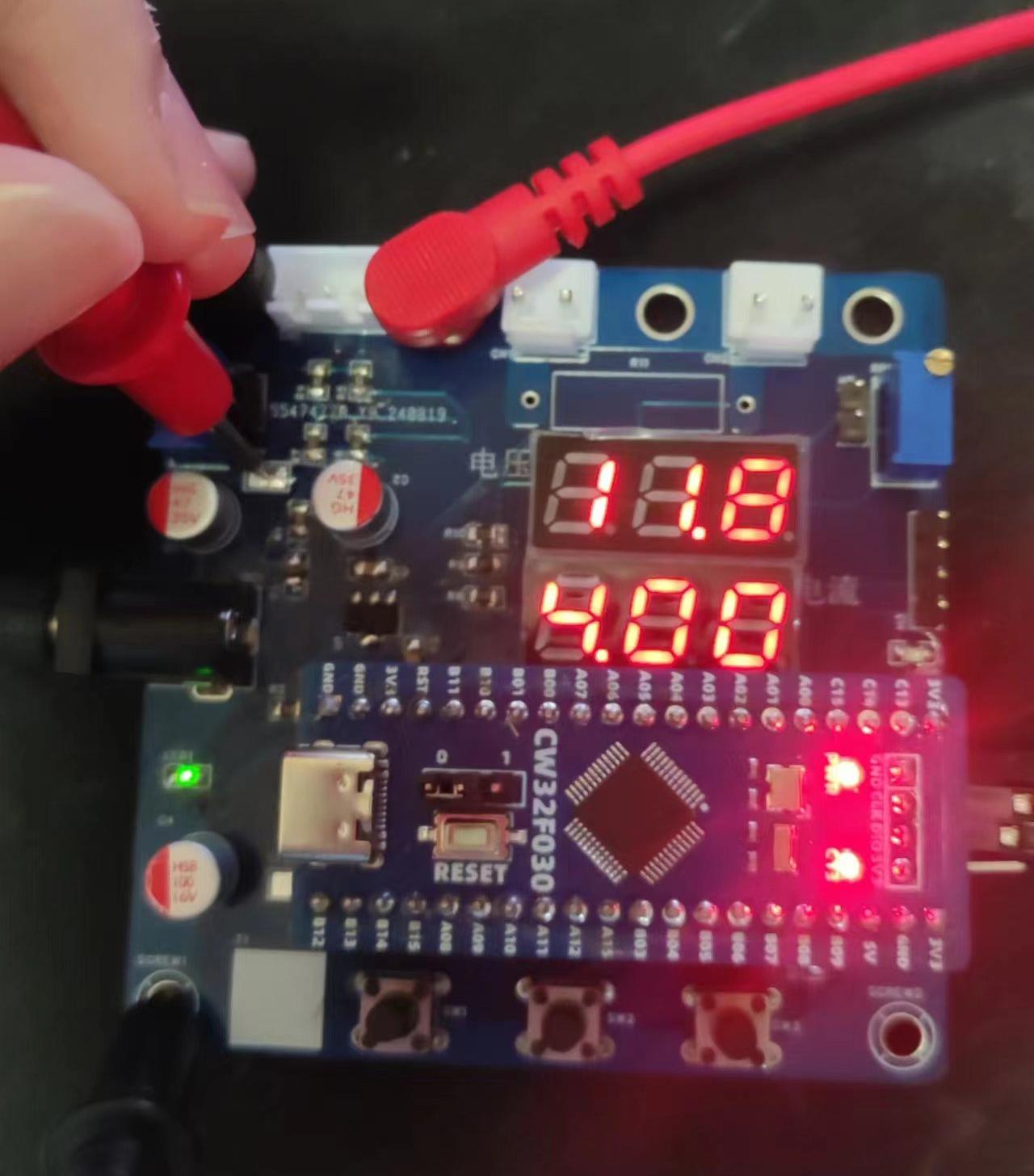
Training Camp Based on CW32F030 Voltage and Current Meter
Voltage and current meters based on CW32 development board
Hardware Part
1. Power Supply Circuit
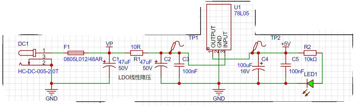
[1] The schematic diagram not only shows the pin connections of each component, but also indicates the direction of current flow during circuit design. First, low-frequency filtering is achieved through electrolytic capacitors, and then high-frequency noise is filtered out through small-capacity capacitors.
[2] When designing a DC plug, attention should be paid to the inner diameter of the DC socket. Common types include DC2.1 and DC2.5. Determine whether the power connector and DC socket are suitable. [3] According to Li Gong's actual test, the power supply current of this circuit does not exceed 100mA, so a 120mA fuse with a 48V withstand voltage and a 78L05 chip are used. [4] Two TP test points are added to facilitate power supply confirmation and self-testing. Because of the common ground, the accuracy is theoretically very high, there is no extra interference, and even the GND line is not needed.
2. Voltage sampling circuit

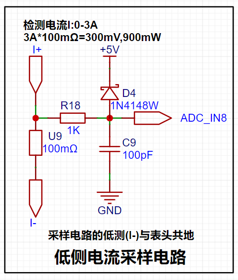
3. Current sampling circuit
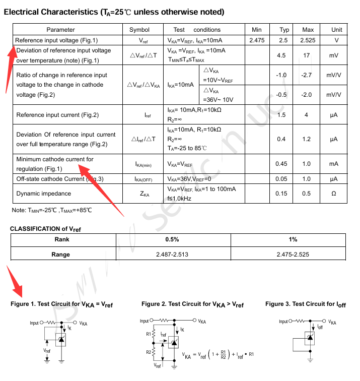
4. TL431 reference voltage
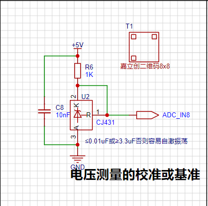
capacitor is used for decoupling. If it is commonly connected between A and R, it may cause self-oscillation, but it is generally not a problem. By using the TL431 circuit to provide a 2.5V reference voltage (actually measured to be about 2.48V), it can be seen from the chip manual that when the chip pins 1 and 2 are connected, VKA=VREF. IKA recommends a maximum current of 1mA, and the current limiting resistor R=(5V-2.5V)/0.001A=2.5K. However, the chip sink current can reach 100mA, and the damage is not significant. For example, with a current limit of 100mA, P=UI=2.5V*100mA=0.25W. Therefore, a power resistor with a current limit of greater than 0.25W should be selected.
5. Display and Operation Circuit

Software Part
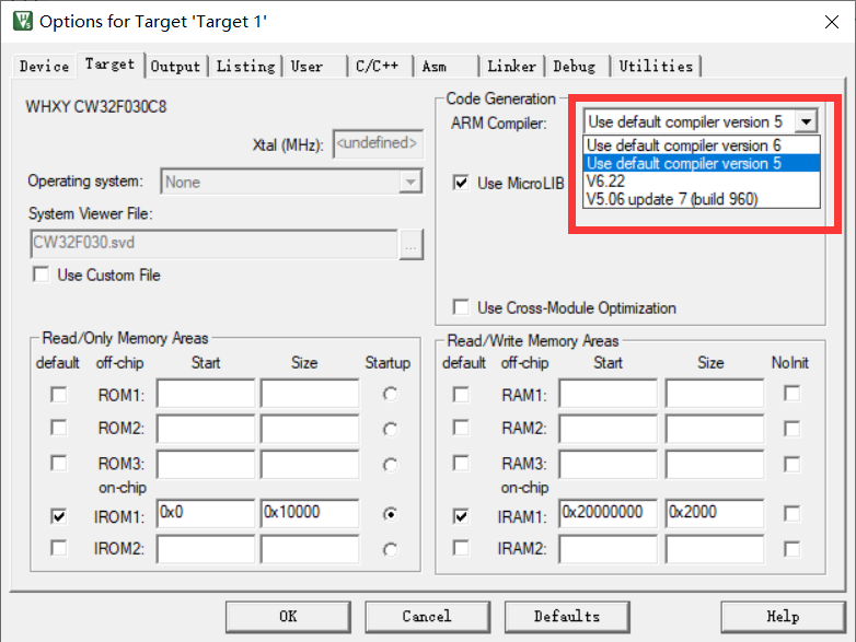
1. Compiler Part
The most frequent question in the discussion group during this training camp was about software installation. The new version of KEIL has reached version 5.40 (May 2024). The download link for this version no longer provides the AC5 compiler, and CMSIS has also been updated to 6.1.0. This makes it impossible to compile most official examples correctly. These two parts need to be modified before compilation. Using version 5.XX in CMSIS is very important.
2. Program Part
The program should be written with reference to the official examples. See the official examples for details.
f36960f21ca9c9de9a9d0563140979ac.mp4
WeChat image_20240825235116.jpg
WeChat image_20240825235119.jpg
WeChat image_20240825235543.jpg
WeChat image_20240825235559.jpg
PDF_Training Camp Based on CW32F030 Voltmeter and Ammeter.zip
Altium Training Camp Based on CW32F030 Voltage and Current Meter.zip
PADS Training Camp Based on CW32F030 Voltage and Current Meter.zip
BOM_Training Camp Based on CW32F030 Voltage and Current Meter.xlsx
92331
Thermal Imaging 4117mini
Based on the TB-4117-3 thermal imager, this device has been modified to support both male and female Type-C connectors, allowing for direct connection and use with mobile phone data cables.
Based on the TB-4117-3 thermal imager, modifications have been made, including the design of a Type-C male and female adapter board, along with a CNC aluminum alloy shell made for 6.6 yuan. The affordable price brings a more premium feel, and the size has been reduced to half of the original, making it more convenient to carry!
Aluminum casing 111.STEP
Lens aluminum housing.STEP
PDF_Thermal Imaging 4117mini.zip
Altium_thermal imaging4117mini.zip
PADS_Thermal Imaging 4117mini.zip
BOM_Thermal Imaging 4117mini.xlsx
92332
32U4 chip 68-key keyboard
A 32u4, 68-key layout keyboard based on QMK.
VID_20240910_122621.mp4
qmk firmware source code.zip
RGB68stm32_default.bin
RGB68_default.hex
PDF_32U4 chip 68 keyboard.zip
Altium_32U4 chip 68-key keyboard.zip
PADS_32U4 chip 68 keyboard.zip
BOM_32U4 chip 68-key keyboard.xlsx
92333
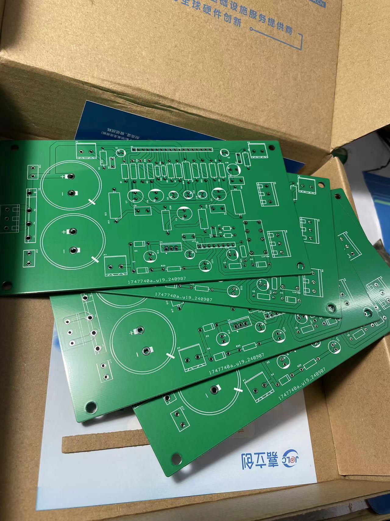
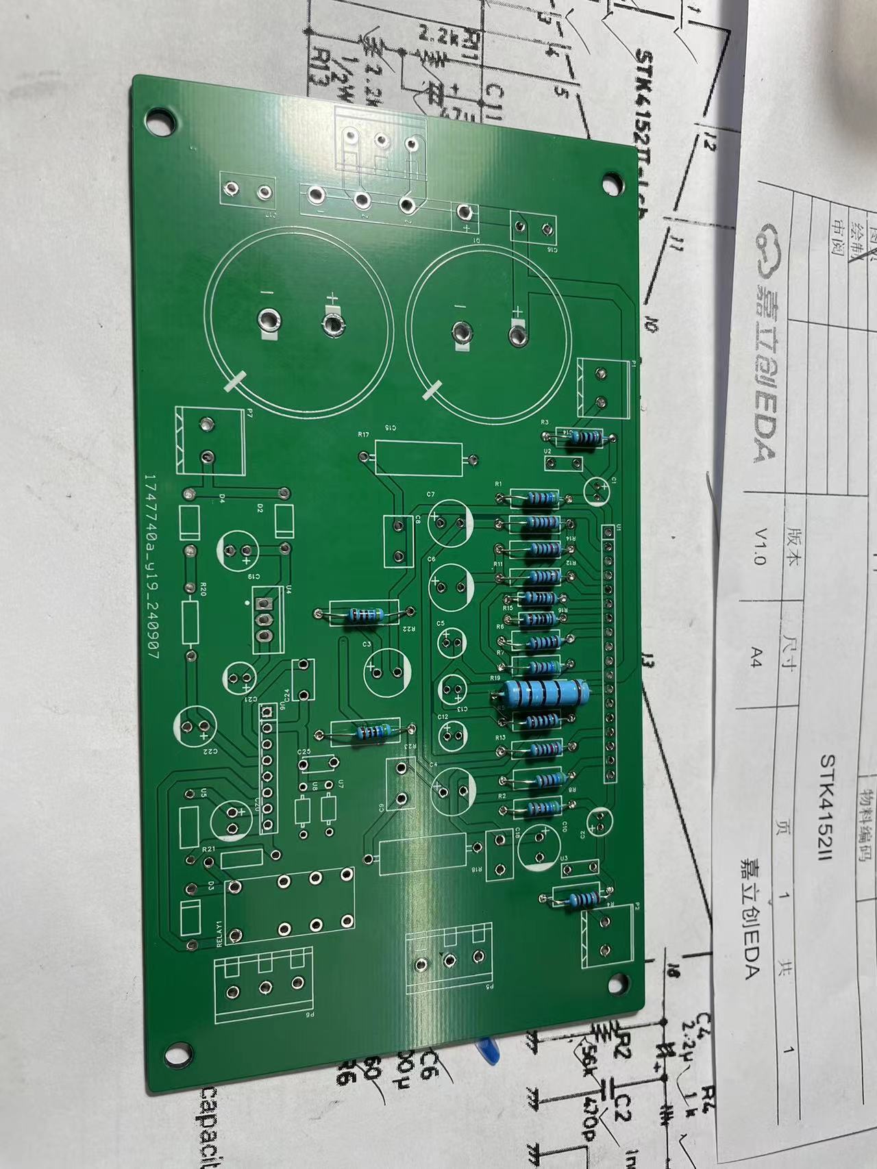
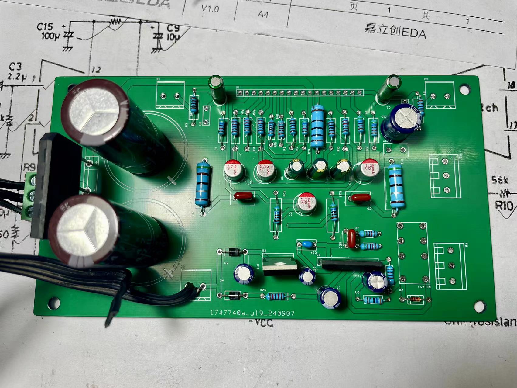
STK4152II
The STK4152II power amplifier module circuit has been successfully tested. It only requires incorrect soldering and can be powered on. This is my first time making an open-source project, so please be understanding.
The STK4152II power amplifier module circuit has been successfully tested. It only requires incorrect soldering and power-on. This is my first time making an open-source project, so please be understanding. [Images
: ![WeChat image_20240911095019.jpg]
![WeChat image_20240911095025.jpg]
![WeChat image_20240911095028.jpg]]
WeChat_20240911094501.mp4
PDF_STK4152II.zip
Altium_STK4152II.zip
PADS_STK4152II.zip
BOM_STK4152II.xlsx
92336
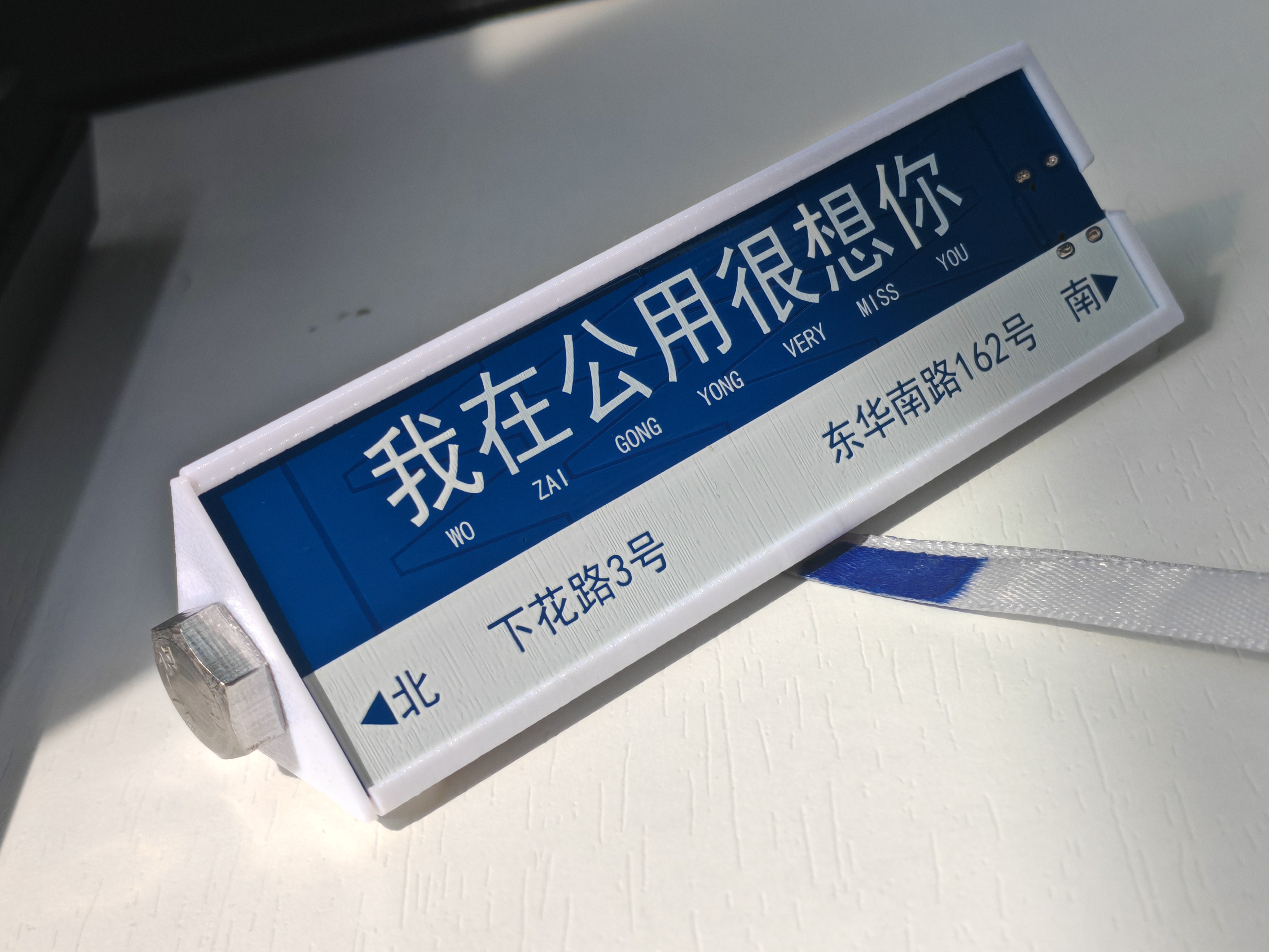
Touch bar with the look of a trendy road sign
The most basic numeric keypad setup,
updated on September 11, 2024, with school address updated.
Actual product photos
User manual
Default mode
| Left | Middle | Right | Swipe left | Swipe right | Zoom in | Zoom out |
| --- | --- | --- | --- | --- | --- | --- | --- |
| Previous track | Play/Pause | Next track | Volume down | Volume up | Enter dial mode | Empty |
Dial mode
| Left | Middle | Right | Swipe left | Swipe right | Zoom in | Zoom out |
| --- | --- | --- | --- | --- | --- | --- | |
Switch speed | Click option | Call up dial | Counterclockwise | Clockwise | Open open source network | Return to default mode |
Custom shortcut keys will be added later.
Assembly instructions
In addition to the two shells, the following accessories are also required
: 1. M8 screws are used for assembly and counterweight. The longest you can use is M8*100.
2. This ribbon is to make it look like a support pole for a road sign.
It passes through the narrow opening below and is then knotted for fixation.
3. Anti-slip feet to prevent it from moving around.
丐Touch_Ver123.hex
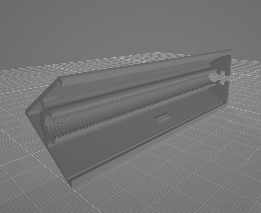
Road sign shell.STL
Road sign casing end cap.STL
Beggar Touch_V123 No Lights.zip
Beggar Touch Sensitivity Adjustment Host Computer.exe
PDF_Touch bar resembling a trendy road sign.zip
Altium Touch Bar with Trendy Road Sign Design.zip
PADS Touch Bar with Trendy Road Sign Design.zip
BOM_Touch bar with trendy street sign design.xlsx
92337
electronic
 shows a hole cut out for heat dissipation.


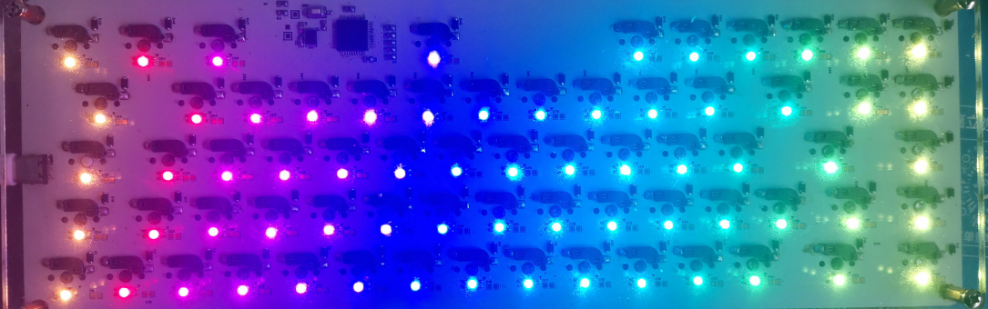 Note that the RGB lighting is full backlighting.


 京公网安备 11010802033920号

 XR-1015CP


