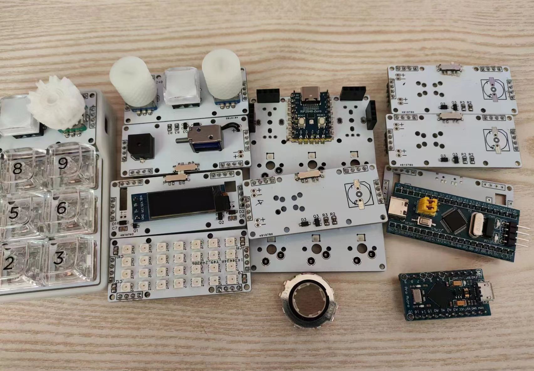
This project mainly includes some special functions of the keyboard, making it convenient for keyboard enthusiasts to find components and for reference, such as knob encoders, solenoid valves, buzzers, vibration motors, small screens, joysticks, and HUB expansion docks. Please read the notes carefully before use! Feedback is welcome in the comments section. This project is open source and will be updated periodically.
I. Attachments: The
attachments include an APM manual and bootloader file
; a table of commonly used capacitors and resistors; a recommended list of special components;
and corresponding firmware and source code for reference.
All keyboards use QMK firmware and support VIA and Vial software. The KFC keyboard uses an STM32F103CBT6 chip, and the ZERO keyboard uses a MicroSnow RP2040-ZERO development board. You can use a ready-made development board from Taobao for programming and testing.
II. Other Notes:
The joystick section has not been verified and may have issues. Please check it yourself, and feedback is welcome in the comments section for correction. All other parts have been verified (the code for the vibration motor and screen is very basic and doesn't have any fancy features).
III. Open Source Declaration
This project is open source under the CC-BY-NC-SA 4.0 license. When reprinting, you must give appropriate attribution (including a link to this project) and indicate whether you have modified the original. This work may not be used for any commercial purpose. If you modify, transform, or alter this work, you may only distribute derivative works created from this work under the same license terms.
① Important Notes (text version attached):
☆☆☆ First, when you are a beginner and don't understand the schematic diagram, please just copy and paste! Do not attempt to create your own if you lack sufficient knowledge! Do not make arbitrary modifications!
☆☆☆ Second, when you are a beginner and learning to draw diagrams from open source projects, do not modify them randomly! Do not stitch things together randomly! Do not delete things randomly! Some circuits cannot be modified randomly! For example, the C port can only be connected to the D+ and D- pins of the main controller; DP can only be connected to D+, and DM to D-. For example, the STM32 programming interfaces—SWDIO and SWCLK—can only be connected to the B13 and B14 interfaces respectively. The screen can only be connected to specific pins with I2C functionality, and the joystick can only be connected to specific pins with ADC functionality. The HUB chip can support four devices simultaneously, but the right-side bus interface needs to be connected to a computer, and the keyboard controller can only be connected to one of the four sets of interfaces on the left. Also, things like programming interfaces, RESET switches, BOOT switches, and external crystal oscillators cannot be deleted arbitrarily. Having a backup plan is crucial; don't regret it when you're forced to redesign the board after a problem occurs! ☆☆☆The F103 series controller requires a programmer; it's recommended to purchase the PW link V2, which costs 9.9 RMB including shipping and includes video tutorials and a service group. ☆☆☆Regardless of the controller chosen, it's recommended to buy a development board with the same controller; this is very useful for troubleshooting hardware and firmware issues.
②Board Design Precautions:
1. Regarding keyboard dimensions and switch packaging data: Refer to the datasheet and specification sheet. These are the manufacturer's certified standard documents. Cherry's original specification sheet uses imperial units; don't be misled by millimeter-based data in some Chinese translations.
2. When placing switches on the PCB, adjust the grid size to [93.75mil] or [187.5mil] because [1U key position = 19.05 mm = 750mil], while the smallest unit for a normal key position is 0.25U = 187.5mil. 3. Place the crystal oscillator as close as possible to the motherboard. 4. Place the control unit not too far from the main controller. The capacitance values of the two capacitors next to the crystal oscillator must be calculated according to the formula; otherwise, the main controller may not recognize them or allow them to work. 5. Filter capacitors should be placed near the respective VCC pins of the chip, not in a single line. When there are multiple capacitors, the smaller capacitor should be closer to the chip.
6. When routing traces, avoid right angles as much as possible; choose 45-degree bends or rounded corners, especially for important signal lines. 7. When routing traces, the spacing between lines should conform to the 3W rule; avoid overcrowding. 8. When routing power lines, such as +5W... V, 3.3V, etc., should be appropriately thickened. Calculation formulas are available online. For keyboard power cables, 15mil is generally sufficient. 8. When routing traces, try to keep them horizontal and vertical, with one vertical and one horizontal trace on each side. 9. When routing traces, current should flow through the capacitor first, then into the chip. 10. When routing traces, try to follow the direction of the long, narrow pad.
11. When routing traces, the area enclosed by a group of important signal lines should be as small as possible. 12. When routing traces, copper pouring can be disabled in important signal line areas, such as Bluetooth antennas and crystal oscillator sections. 13. [The text abruptly ends here, likely due to an incomplete sentence or missing information.] When routing, important signal lines should be as equal in length as possible, such as the D+/D- data lines and the crystal oscillator data line. However, for a keyboard, USB 2.0 doesn't have high requirements; a length difference of less than 100mil between the two lines is sufficient. 14. When routing, you can ignore the GND line initially and lay copper directly after routing other lines. Only manually route lines where copper laying cannot solve the problem. 15. After laying copper, you can drill GND vias wherever there is space. These are called seam holes and can ensure good grounding of the board.
16. The two 5.1K resistors on the TYPE-C port are used to identify the C port. For the Type-C cable, soldering is optional if not needed. If required, two 5.1K resistors must be connected separately; do not cut corners by using only one. 17. For the STM32F103 series main controller, the PC13/PC14/PC15/PA0 pins have weak power supply capabilities, so try to avoid using them, especially for driving lights or solenoid valves. Connecting them to button matrices or knobs is fine. 18. JLCPCB factory process parameters: https://www.jlc.com/portal/vtechnology.html
③ Other precautions:
When soldering, prioritize soldering the Type-C port and the main controller. If you mess up the soldering, just throw it away and replace it with a new board. If you're really bad at soldering, ask someone to help you. Don't make things difficult for yourself. Pay attention to the polarity and direction of components when soldering, especially diodes and RGB LEDs. RGB LEDs must be those with integrated ICs; do not mistakenly buy those with common cathode and common anode configurations.
1. Other keyboard tutorial recommendations: Tutorials by Bilibili user "阿熊话太大" (https://space.bilibili.com/439415853),
open-source projects such as "APM/STM32F103CxT6 Minimum System Board" by LCSC user HiryKun, and video tutorials by other Bilibili users like "办达达," "浮灵," and "丈二." My homepage also has other keyboard case projects for reference.
2. Other commonly used component packages recommendations: Component library by LCSC user tianguaapple, and LCSC user LAN_23333. For special components, find them yourself in the LCSC component library or user contribution library. Remember to compare them with the datasheet, paying attention to the polarity and package specifications of the components. Only use them after confirming that everything is correct.
3. Commonly used customization websites: ① Nine-Fox website: https://nine-fox.com/#/home
One-stop service for rendering, keycap design, and three-mode PCB (three-mode requires the Wenlaoban main controller). It can generate various cotton drawings, positioning board drawings, and basic shell 3D drawings and PCB draft files with one click (3 yuan to download the complete set of files) ② AI03 positioning board generation website: https://kbplate.ai03.com/
This website has more accurate data and is much better than the old website commonly used in the keyboard community ③ QMK official documentation:
https://docs.qmk.fm/#/ ④ VIA official
website: https://www.caniusevia.com/ ⑤ VIAL official website: https://get.vial.today/
⑥ Keyboard layout editor website: http://www.keyboard-layout-editor.com/
⑦ 32U4 firmware generation website, not recommended: https://kbfirmware.com/ ⑧ Old positioning board generation website, not recommended: http://builder.swillkb.com/
4. Tencent Weiyun sharing: https://share.weiyun.com/TdqXRrSR
Includes my VIA environment package, VIAL environment package, VIAL software, VIAL software, MSYS software, toolbox software, etc.
The general process for beginners to make keyboards: >>> Watch the video tutorials on Bilibili (watch them completely, and then join the UP's group) >>> Find a few reliable open source projects for reference, draw the schematic diagram and PCB board, and it is best to send them to the group members to check for problems >>> Place an order for board making, purchase components, and wait for delivery >>> During the days of waiting for delivery, you can learn how to install the QMK environment and how to compile the QMK firmware >>> After the board arrives, solder the main components (such as the keycaps and keycaps first). (No rush) >>> Connect to the computer and test for short circuits, power surges, or no response. >>> Use a programmer to burn the BootLoader file (some controllers may not need this). >>> After burning the BootLoader, connect to the computer and see if the controller can be recognized normally (the device name for the STM32 chip is maple003). >>> Install the QMK environment and compile the QMK firmware. >>> Use the qmk_toolbox software to burn the corresponding keyboard firmware (VIA and Vial are different software, and the corresponding keyboard firmware is also different; I personally recommend using Vial, as it is more powerful and convenient). >>> Test if all keyboard functions are normal. If there are any problems, you can use the development board to burn the firmware to see if it is a hardware problem or a firmware error.


 京公网安备 11010802033920号

 EC3F-T-20-30.000M-CL175


