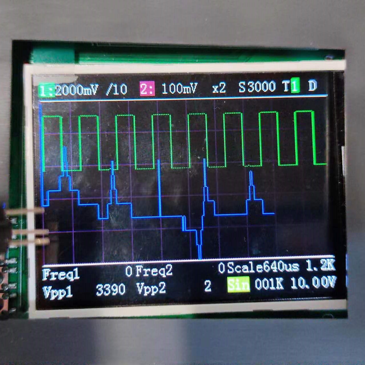
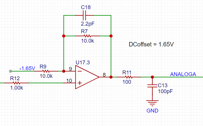
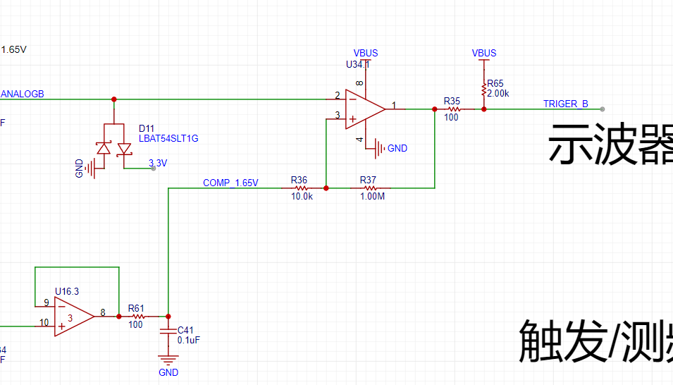
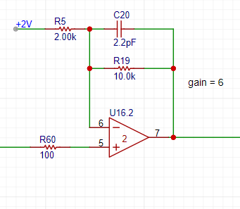
 explained below. We will first briefly introduce the analog input and output channels on the oscilloscope expansion board, and then explain the design and calculation methods in detail later. The signal enters from the oscilloscope input terminal. Here, a 1MΩ input impedance is achieved through a series resistor voltage divider, generating two signals for selection: one is a direct input, and the other is attenuated to 1/20. A relay is used as a switch to select either the direct signal or the attenuated signal to enter the first-stage non-inverting amplifier. The non- inverting amplifier performs two tasks: first, it amplifies the input signal at the non-inverting terminal by a factor of two; second, it shifts the amplified signal by 1.65V, calculated as Vo = 1.65 + 2*Vi. Therefore, the overall gain of the corresponding circuit is 2 times or 1/10 times. The output of the non-inverting amplifier is sent to the STM32H750 ADC. The trigger/frequency measurement signals AnalogA and AnalogB, along with the DC reference level (generated by one of the H750's DACs), are passed through a comparator to generate a square wave signal, which is then fed into the STM32H750's timer for frequency measurement. DAC_OUT2 is the DC reference level, emitted through the STM32H750's internal DAC2 configuration. The output channel uses a two-stage RC filter to function as a low-pass filter . The output amplifier amplifies the non-inverting input by 6 times and then shifts the amplified signal by -10V before outputting it. In conclusion, this training camp was time-constrained, and some functions were not yet fully debugged; further improvements will be made later.


All reference designs on this site are sourced from major semiconductor manufacturers or collected online for learning and research. The copyright belongs to the semiconductor manufacturer or the original author. If you believe that the reference design of this site infringes upon your relevant rights and interests, please send us a rights notice. As a neutral platform service provider, we will take measures to delete the relevant content in accordance with relevant laws after receiving the relevant notice from the rights holder. Please send relevant notifications to email: bbs_service@eeworld.com.cn.
It is your responsibility to test the circuit yourself and determine its suitability for you. EEWorld will not be liable for direct, indirect, special, incidental, consequential or punitive damages arising from any cause or anything connected to any reference design used.
Supported by EEWorld Datasheet
EEWorld
subscription
account

EEWorld
service
account

Automotive
development
community

Robot
development
community

About Us Customer Service Contact Information Datasheet Sitemap LatestNews


Room 1530, 15th Floor, Building B,
No.18 Zhongguancun Street,
Haidian District,
Beijing, Postal Code: 100190
China
Telephone: 008610 8235 0740
 京公网安备 11010802033920号

 C0805C103C2GAC


