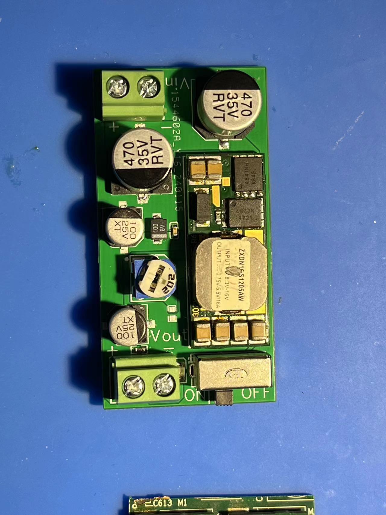
On the secondhand trading platform Xiaohuangyu, I found a very affordable ZTE DC-DC non-isolated power module for only 4 yuan. The main function of this power module is to convert 12V to a stable 5V output, with a maximum allowable input voltage of 16V and a maximum output current of 16 amps. Notably, it also features adjustable output voltage. If voltage adjustment is not needed, simply solder a fixed resistor R1 with a resistance of 1.35kΩ. This allows the module to demonstrate good compatibility and practicality in various application scenarios.
To facilitate use, I have designed a matching expansion board schematic, which you can directly use for PCB fabrication or modify the interface configuration according to your needs. Theoretically, upgrading the internal capacitors to 1000µF would further reduce output voltage ripple.
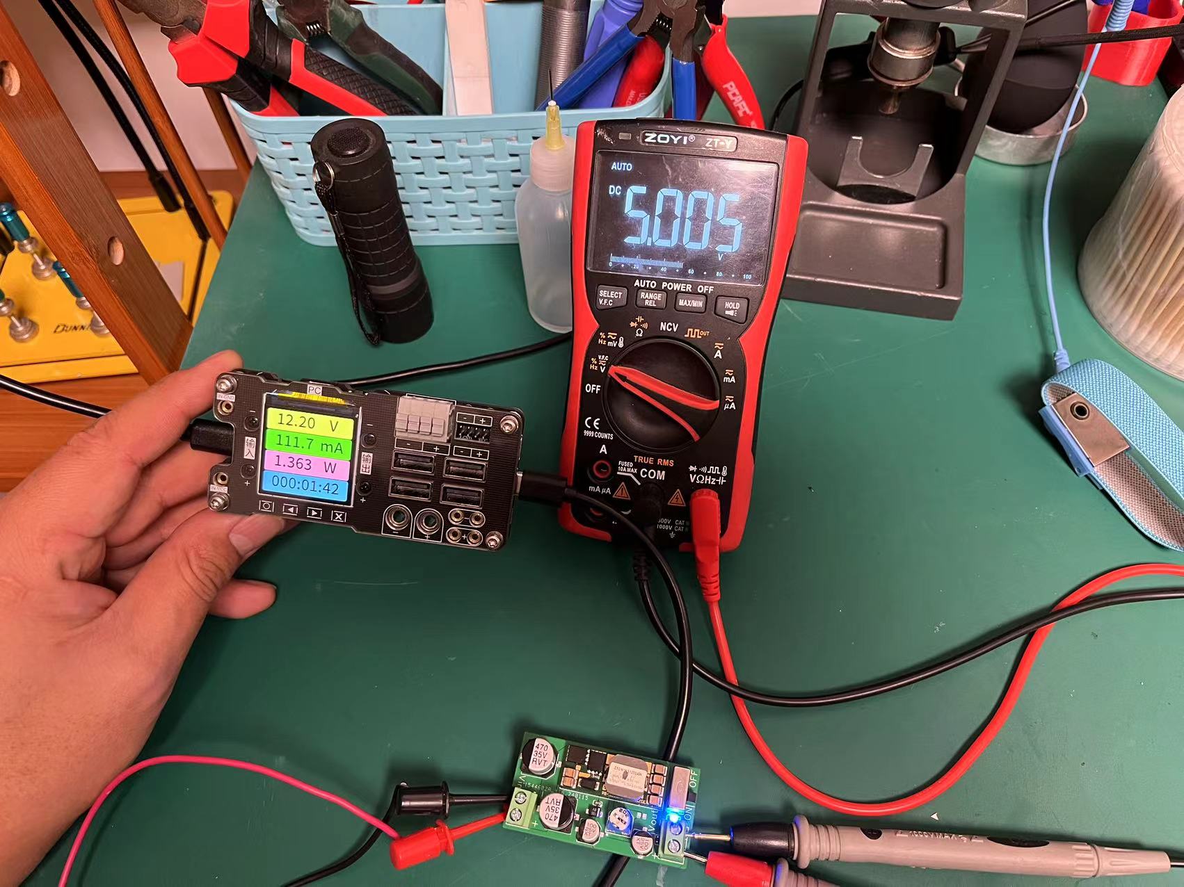
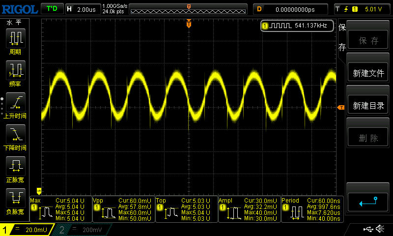
Under my current testing conditions, the peak-to-peak output ripple of this power module under no-load conditions reached 60mV. It should be noted that due to limitations, these measurements were obtained under no-load conditions. Meanwhile, I also observed that the module's quiescent current is approximately 110 mA when no device is loaded, which translates to a quiescent power consumption of about 1.3 watts. It also exhibits slight heat generation during operation.
Despite these issues, considering its price and basic performance, this ZTE power module still offers high cost-effectiveness and is a worthwhile option.
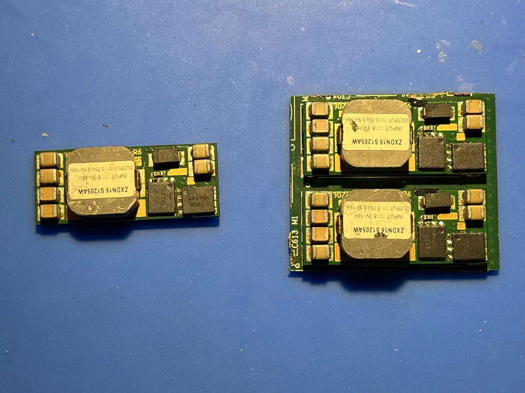
When purchasing, it is particularly important to note that to ensure correct installation and use, it is strongly recommended to choose the version with the original baseboard, as original pins are required.
Furthermore, there are many other affordable power modules available on the platform. However, please be aware that this power module is a non-isolated design, meaning there is no electrical isolation between the input and output. Therefore, circuit safety and system design requirements must be carefully considered in specific applications. Regarding the extended version, there is no technical aspect to it; users can modify it according to their actual needs.
PDF_Super Cheap ZTE ZXDN16S1205 Power Module Expansion Board.zip
Altium_Super Cheap ZTE ZXDN16S1205 Power Module Expansion Board.zip
PADS_Super Cheap ZTE ZXDN16S1205 Power Module Expansion Board.zip
BOM_Super Cheap ZTE ZXDN16S1205 Power Module Expansion Board.xlsx
96335
A certain TB6642 DC brushed driver module baseboard V1.0
A rapid verification solution for a TB6642 DC brushed driver module baseboard, which secures the motor and module, and features pin headers for easy DuPont wire connections.

The module base plate is fixed with M3*8+5 copper pillars and M3 nuts.
The module + encoder motor (12V, 620r) totals 72, and the total cost of the set is about 80.
Hardware
connection board A and B interfaces are directly connected to the encoder
PWM. IN1 and IN2 are controlled by
PWM output from the control board for speed regulation. IN1 and IN2 control the direction. See the truth
table for details.
Simplified test method: set IN1 and IN2 high and low respectively, PWM duty cycle 50, and the motor can be driven. Note : No
precautions . ( Other attachments are uploaded TB6642 datasheet, see attachment for details) // 2024/1/18 21:45
TB6642FG_datasheet_en_20141208.pdf
PDF_TB6642 DC Brushed Driver Module Baseboard V1.0.zip
Altium_TB6642 DC Brushed Driver Module Baseboard V1.0.zip
PADS_TB6642 DC Brushed Driver Module Baseboard V1.0.zip
BOM_TB6642 DC Brushed Driver Module Baseboard V1.0.xlsx
96337
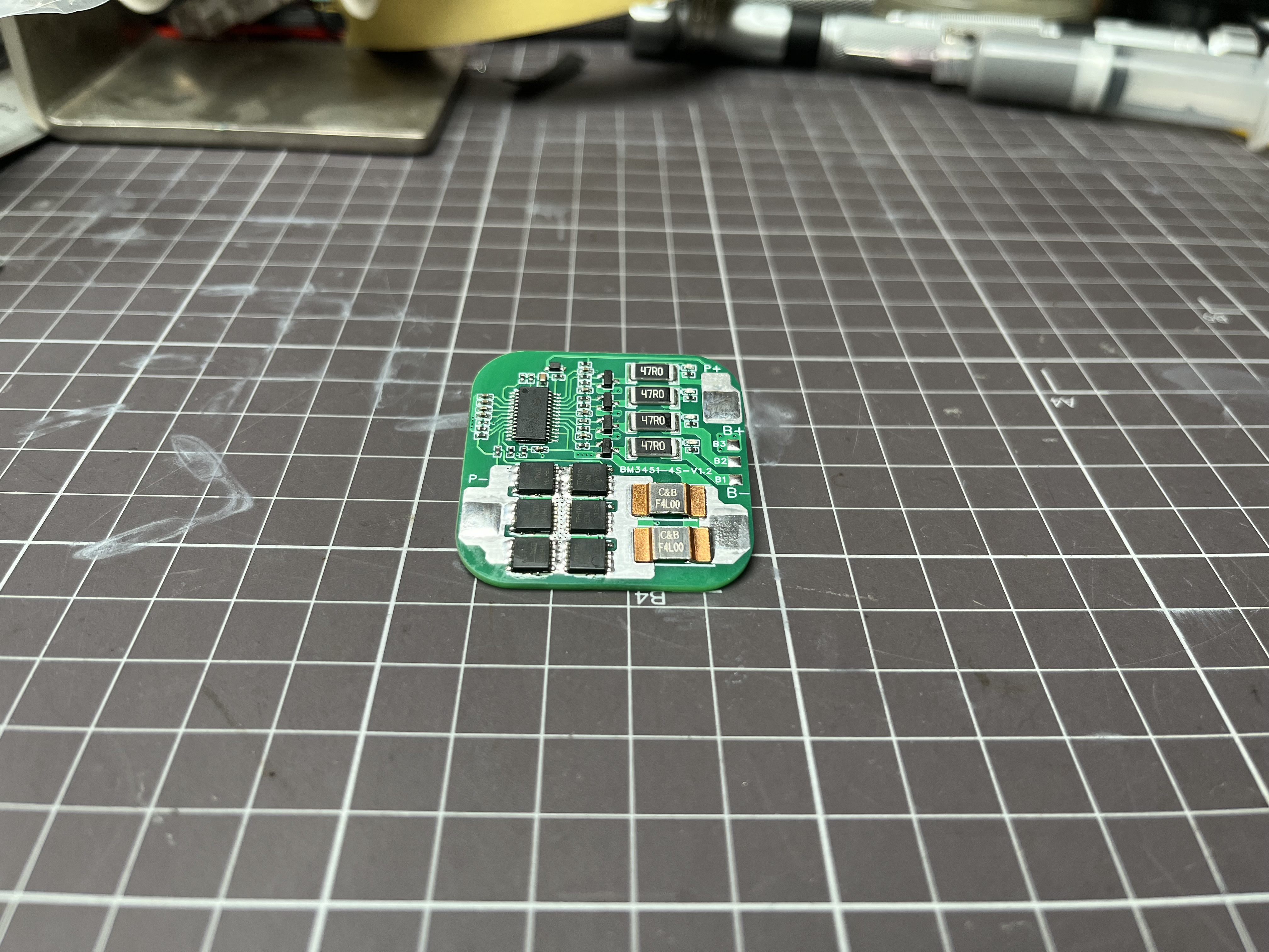
BM3451 [Four-cell Lithium Battery Protection Board 6MOS Upgrade Version]
A four-string battery protection board with equalization design based on BYD's BM3451TNDC-T28A battery management chip.
======WARNING======
The BOM (Bill of Materials) should be based on the schematic diagram! Do not use the BOM
in the project description directly! The BOM should be based on the schematic diagram! Do not use the BOM in the project description directly
! The BOM should be based on the schematic diagram! Do not use the BOM in the project description directly!
Please follow the CC-BY-NC-SA 3.0 open-source license. This project is for learning and research purposes only and is prohibited for commercial use.
Electronics exchange groups: 232586710, 345731137. This is
a four-cell battery protection board with equalization designed based on the BYD BM3451TNDC-T28A battery management chip.
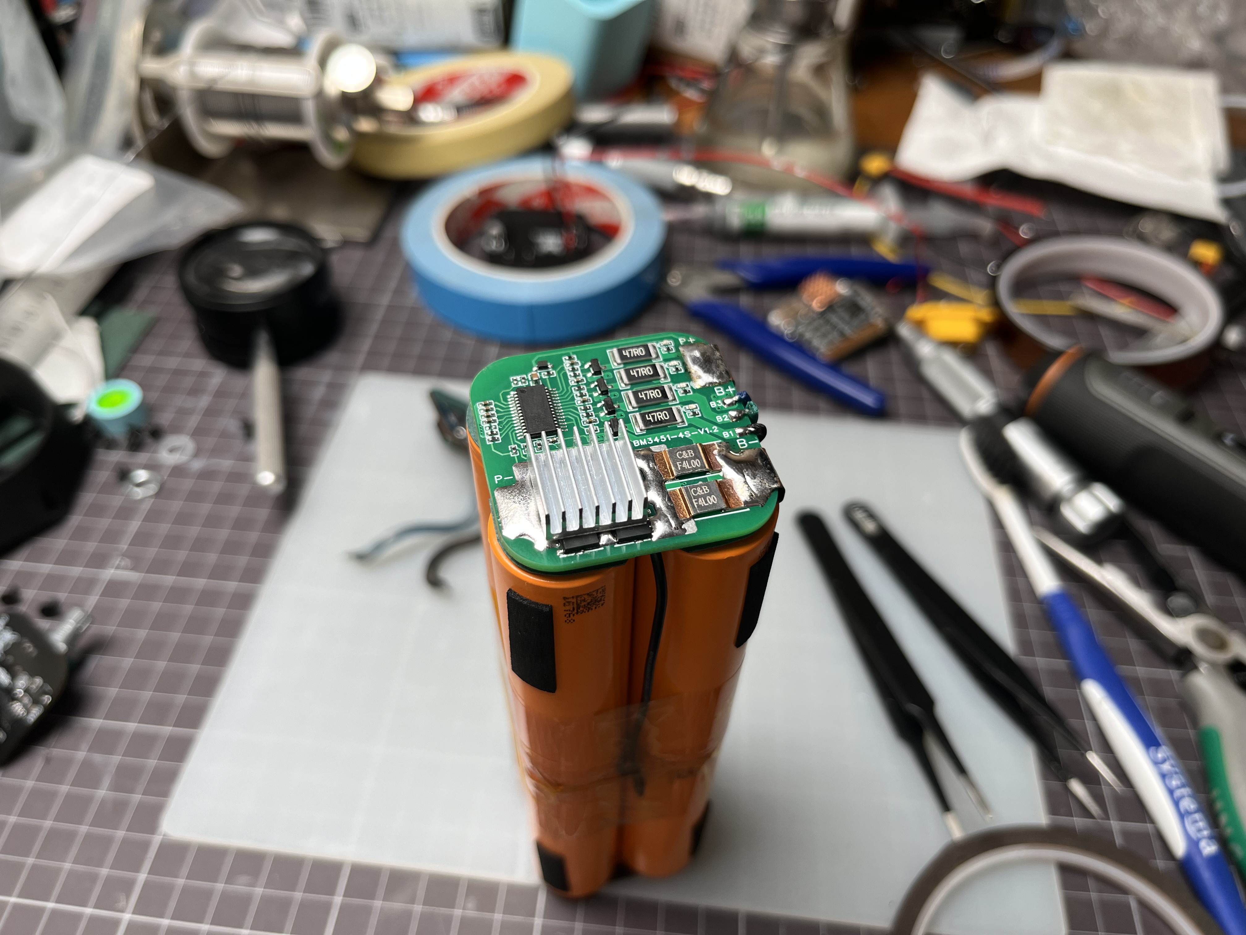
The form factor is adapted to the stacked arrangement of four 21700 batteries, featuring a small size and minimal space consumption.
It includes an equalization indicator light, which illuminates during battery equalization, allowing you to clearly see which battery is being equalized.
This protection board is fully functional, providing protection against overcharge, over-discharge, overcurrent discharge,
short circuit, and overcurrent charging by detecting the voltage and charging/discharging current of each battery cell. The BM3451 offers a battery capacity balancing function to eliminate capacity differences between cells in the battery pack, extending battery life.
The board also features optional high-temperature protection; it shuts off output when high battery temperature is detected and restarts output once the battery temperature drops.
This system is suitable for four-string battery packs with a nominal 3.7V and a fully charged 4.2V ternary lithium-ion battery combination. The
overcharge detection voltage is 4.250V
, the overcharge release voltage is 4.190V
, the over-discharge detection
voltage is 2.800V, the over-discharge release voltage is 3.000V,
the overcurrent protection current is 50A (default) ,
the balancing start
voltage is 4.190V, and the overcurrent detection voltage is 100mV. 100 / set current = current sensing resistor value. For example, 100mV / 20A = 5mΩ.
To connect the protection board to the battery, first solder the battery negative terminal pad, then solder B1, B2, B3, and the balancing node in sequence, and finally solder the battery positive terminal pad. Do not reverse the soldering order.
The MOSFETs will heat up during prolonged high-current operation; therefore, heat sinks must be used for heat dissipation.
PDF_BM3451[Four-cell lithium battery protection board 6mos upgraded version].zip
Altium_BM3451 [Four-cell lithium battery protection board 6mos upgraded version].zip
PADS_BM3451 [Four-cell lithium battery protection board 6mos upgraded version].zip
BOM_BM3451 [Four-cell lithium battery protection board, 6MOS upgraded version].xlsx
96338
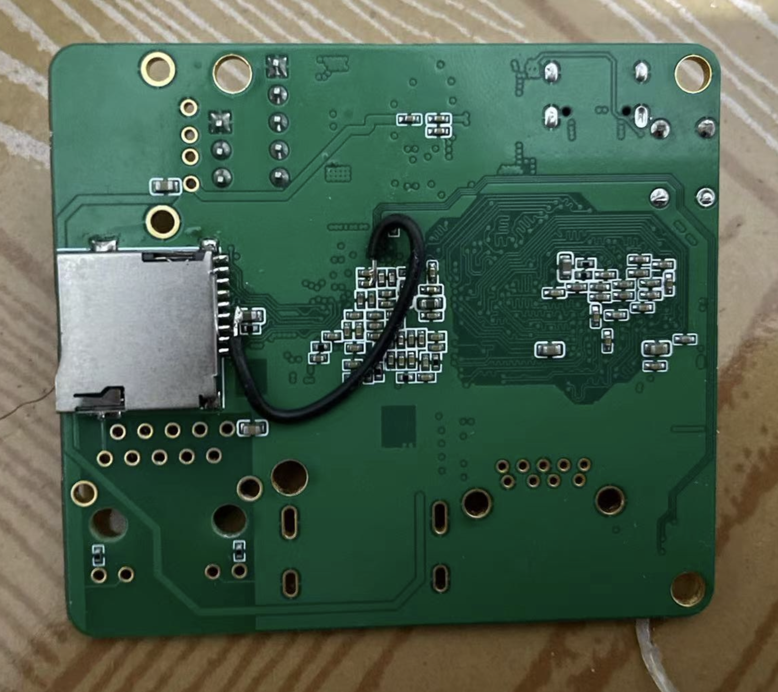
Rockchip RK3328 small board
A board based on Rockchip RK3328
The schematic is still based on Xunlong, but one gigabit Ethernet port has been removed and replaced with USB 3.0.
DDR runs without problems
, but there are some issues with burning the R1 system. It can enter the kernel start stage, but fails to boot, reporting a network card
problem:
YT8531 Ethernet is not working;
LPDDR3 1.8V is not connected;
TF card 3.3V is not connected.

PDF_Small board of Rockchip RK3328.zip
Altium_Rockchip RK3328 small board.zip
PADS_Rockchip RK3328 small board.zip
96340
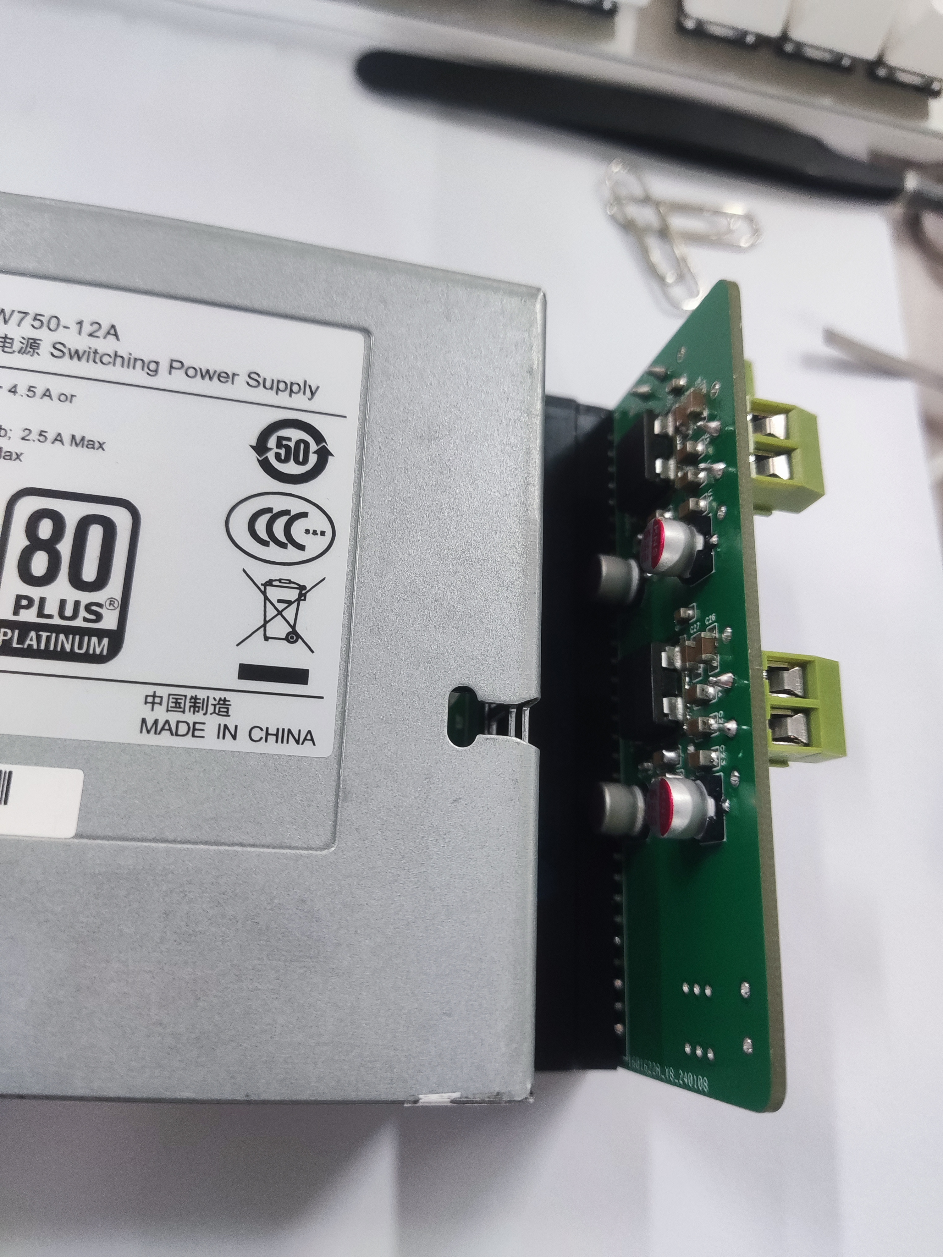
NAE12S20-DC12V-5V-3.3V Verification Board
(Works, but not very well) It uses a NAE12S20DCDC power module, outputting 12V, 5V, 3.3V, and 12Vsb.
I plan to connect an ATX power adapter board later.
The NAE12S20 is a package-in-package (PSiP) DC-DC power module with an input voltage range of 3V~14V, a maximum output current of 20A, and an adjustable output voltage range of 0.6V~5.5V.
Efficiency: 92%, module power: 8W.
On Xianyu (a Chinese online marketplace), the module costs approximately 4 RMB each. A PAC750W server power supply
costs approximately 45 RMB each. This is just a verification board for the NAE12S20 power module; the component specifications are selected according to Huawei's official chip datasheet. In actual use, enhanced heat dissipation and high-current layout are essential. Each chip consumes approximately 1W (12V*0.18A) without load, which is extremely hot! Do not use low-temperature solder (138℃) on the soldering station as it may melt! Do not solder for too long, or the chip base will fall off!
The accuracy of the 5V and 3.3V adapters depends on the accuracy of R3 and R6.
PDF_NAE12S20-DC12V-5V-3.3V Verification Board.zip
Altium_NAE12S20-DC12V-5V-3.3V Verification Board.zip
PADS_NAE12S20-DC12V-5V-3.3V Verification Board.zip
BOM_NAE12S20-DC12V-5V-3.3V Verification Board.xlsx
96341
Bluetooth remote-controlled self-balancing scooter (supports four-wheel Ackerman structure)
[Recorded on a balance bike; I'm not very good at adjusting parameters, so please bear with it.]
[Recorded on a balance bike; I'm not very good at adjusting parameters, so please bear with it.]
35d4f0129b9aa63b9e2f938dec6a2dde.mp4
PDF_Bluetooth Remote Control Balance Car (Supports Four-Wheel Ackerman Structure).zip
Altium Bluetooth Remote Control Balance Car (Supports Four-Wheel Ackerman Structure).zip
PADS Bluetooth Remote Control Balance Car (Supports Four-Wheel Ackerman Structure).zip
BOM_Bluetooth Remote Control Balance Car (Supports Four-Wheel Ackerman Structure).xlsx
96343
electronic


 京公网安备 11010802033920号

 C052C109G5G5CA


