In creating
this project, I was deeply inspired and learned from many excellent open-source projects. These projects provided me with valuable experience, allowing me to better learn.
Although I drew inspiration from these excellent projects, I am also fully aware that my project may have room for improvement. Therefore, I warmly welcome your feedback and suggestions. If you find any problems or have any ideas for improvement, please feel free to share them; I will study and improve them very seriously.
Currently, the software is not yet complete, and the code is still incomplete; the motor driver will be replaced later.
Note: In practical applications, it was found that the RZ7899 cannot use excessively high-frequency PWM control, otherwise it is easily burned out; and it is not suitable for projects requiring precise control.
I. Pin Assignments
: UART:
USART1 (RX:PA9; TX:PA10) – Serial Port;
USART2 (RX:PD6; TX:PD5) – Bluetooth;
USART3 (RX:PB11; TX:PB10) – K210
; USART6 (RX:PG9; TX:PG14) – Spare;
SPI:
CS0 – PE4
; CS1 – PC13
; SCK – PE2 ;
MOSI – PE6;
MISO – PE5;
I2C:
I2C1 (SCL:PB6; SDA:PB7)
; ADC:
ADC01_IN4 (PA4) – Power Supply Voltage Detection;
ADC01_IN8 (PB0) – M2 Current Detection;
ADC01_IN14 (PC4) – M1 Current Detection
; CAN:
CAN1 (RX:PD0; TX:PD1);
PWM:
TIMER8_CH1 (PC6) – Motor M1-IN1
; TIMER8_CH2 (PC7) – Motor M1-IN2
TIMER12_CH1(PB14)——Motor M2-IN1
TIMER12_CH2(PB15)——Motor M2-IN2
TIMER9_CH1(PA2)——Servo 1
TIMER9_CH2(PA3)——Servo 2
TIMER1_CH1(PA8)——Spare
TIMER13_CH1(PA6)——Buzzer
Encoder:
TIMER3_CH1(PB4)——Motor M1-A
TIMER3_CH2(PB5)——Motor M1-B
TIMER2_CH1(PA5)——Motor M2-A
TIMER2_CH2(PB3)——Motor M2-B
PS2:
CS——PF9
CLK——PF6
CMD——PF8
DAT——PF7
II. Schematic Design
1. Power Supply Design

The DC-DC circuit uses SGM6132 (3A, 28.5V, 1.4MHz Step-Down) from Sanbang Microelectronics. The converter
schematic was designed based on the official typical application.

Because the input power supply voltage is too high to be directly used for motor power, two chips are used for separate power supply, one on each side.
The LDO circuit uses the classic AMS1117-3.3 (SOT-89), mainly to power devices that may be connected later, such as Bluetooth modules and LoRa modules that can use UART communication. It was added separately in case the power supply of the core board was insufficient.
2. The motor drive/current sampling circuit
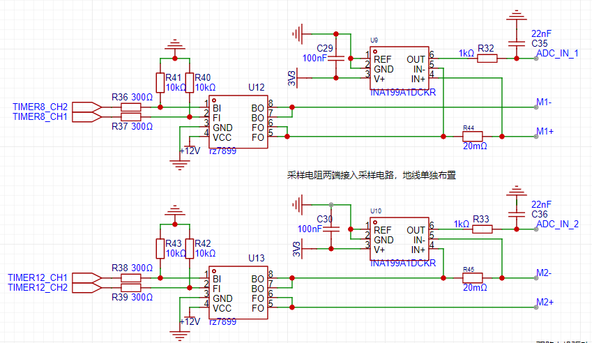
uses the RZ7899 driver, with a peak output current of 4.3A. The stall current of the MG513P20_12V motor is 3.2A, which is sufficient.
The current sampling uses the INA199A1DCKR; this series of devices uses a zero-drift architecture with low offset, so when performing current sensing, the maximum voltage drop across the shunt resistor can be kept at a minimum of 10mV at full scale.
Features:
Wide common-mode range: –0.3V to 26V
Offset voltage: ±150μV (maximum) (supports 10mV full-scale shunt voltage drop)
Accuracy: – Gain error (maximum over-temperature error): – ±1% (Version C) – ±1.5% (Versions A and B) – 0.5µV/°C Offset drift (maximum) – 10ppm/°C Gain drift (maximum)
Quiescent current: 100μA (maximum)
Sampling resistor value calculation: Rsense < PDmax / Imax^2
Gain range Vsn / (Imin Rsense) < GAIN < Vsp / (Imax Rsense)
The appropriate sampling resistor can be selected based on your input current and power supply. Here, a chip with a sampling resistor of 20mΩ and a gain of 50V/V is selected.
A filter circuit is connected after sampling to optimize the sampling.
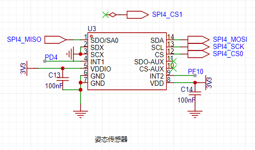
3. The attitude sensor
uses the QMI8658A, which supports a maximum SPI clock of 15MHz and a maximum IIC clock of 400kHz.
4. The magnetometer
uses the QMC5883P, but since it doesn't support SPI, the I2C protocol is used. 5.

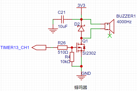
A
passive electromagnetic surface-mount buzzer is used, operating at 2-4V and 4000Hz.
Because it's an inductive component, the current cannot be converted forward, so a freewheeling diode (D2) is used to reduce the reverse induced electromotive force generated across the buzzer, protecting the driving MOSFET; a current-limiting resistor (R26) is used to protect the PWM output pin of the microcontroller.
6. The ADC circuit
uses a series resistor divider. Since the voltage at the ADC pin cannot exceed 3.3V, a bidirectional TVS diode is used to protect the microcontroller pin; power supply voltage detection and two-channel current sampling are used.

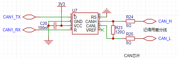
7. CAN communication
uses a SIT65HVD230DR, powered by 3.3V, with a maximum speed of 1Mbps.
The VREF pin is the Vcc/2 reference output pin; it's not connected if not used. Rs is the mode selection pin. Strong pull-down to GND = high-speed mode; strong pull-up to VCC = low-power mode; pull-down to GND through a 10kΩ to 100kΩ resistor = slope control mode.
Note that RX is connected to R and TX to D. The CAN bus requires two 120Ω terminating resistors. Terminating resistors must be connected at both ends of the CAN bus for it to function properly. The purpose of the resistors is to match the bus impedance and improve the reliability of data communication.
III. PCB Design
1. DC-DC Step-Down
: Minimize loop area to reduce electromagnetic interference.
Avoid cross-layout of components to reduce mutual interference.
Separate input and output loops to reduce crosstalk.
Use area fill instead of wires.
Consider heat dissipation to ensure normal component operation.
Leave redundancy in the design
. Since the input voltage in this project is 16V, two resistors are used, one on the front and one on the back. Due to limited PCB space, two different loop designs are used.
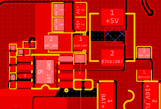
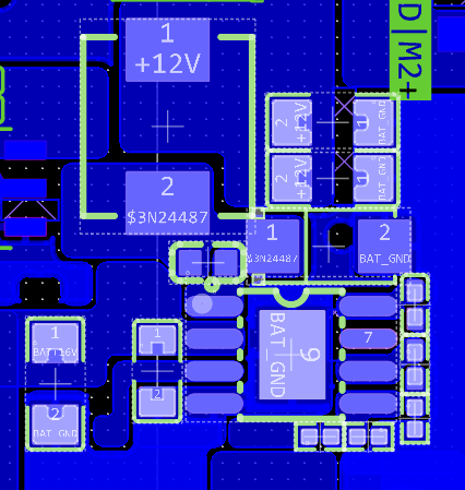
Note that the feedback resistor should be as close to the chip pin as possible.
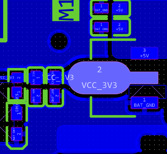
2. LDO Step-Down:
Use the classic AMS1117-3.3. Note that the package used is SOT_89.
3. Motor Drive/Current Sampling Circuit:
Since the motor is a high-power device with a stall current of 3.2A, care must be taken to prevent the copper foil from burning out. Routing should be done on the top and bottom layers as much as possible. Thicker copper foil provides better heat dissipation. Use area fill for routing.
The sampling resistor is connected using the Kelvin method, and the ground wire is laid out separately to reduce interference.

4. The attitude sensor and magnetometer
use an islanded design to minimize interference.

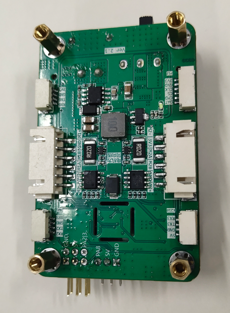
IV. Physical Display

video_20231029_174623.mp4
GD32F4_Demo.zip
PDF_Liangshan School Car Control Board.zip
Altium_Liangshanpai Car Control Board.zip
PADS_Liangshanpai Car Control Board.zip
BOM_Liangshan School Car Control Board.xlsx
97323
CH582M Development Board - Sugar Edition
CH582M Development Board
Project Introduction:
A microcontroller with USB, BLE 5.3, and 40 I/O ports, priced at only 3 yuan. Except for the slightly limited SRAM, it's quite attractive.
This project has been board-made and verified to be usable.
This project is based on the schematic of the Qinheng official EVT development board, with some simple adjustments. An I2C interface is provided for connecting a temperature and humidity sensor. The
temperature sensor used is a very inexpensive AHT20/21 temperature and humidity sensor. Other than that, the silkscreen printing was stylized, and one of my favorite characters, Sugar Sauce, was added. You can modify or delete it if you don't like it. A white board is recommended for better backlighting.
The antenna used is the official antenna, and a simple 50Ω impedance matching was done. The effect is shown in the picture for fun.
A 1.2mm thick board is required.
Physical demonstration:
front

and back,
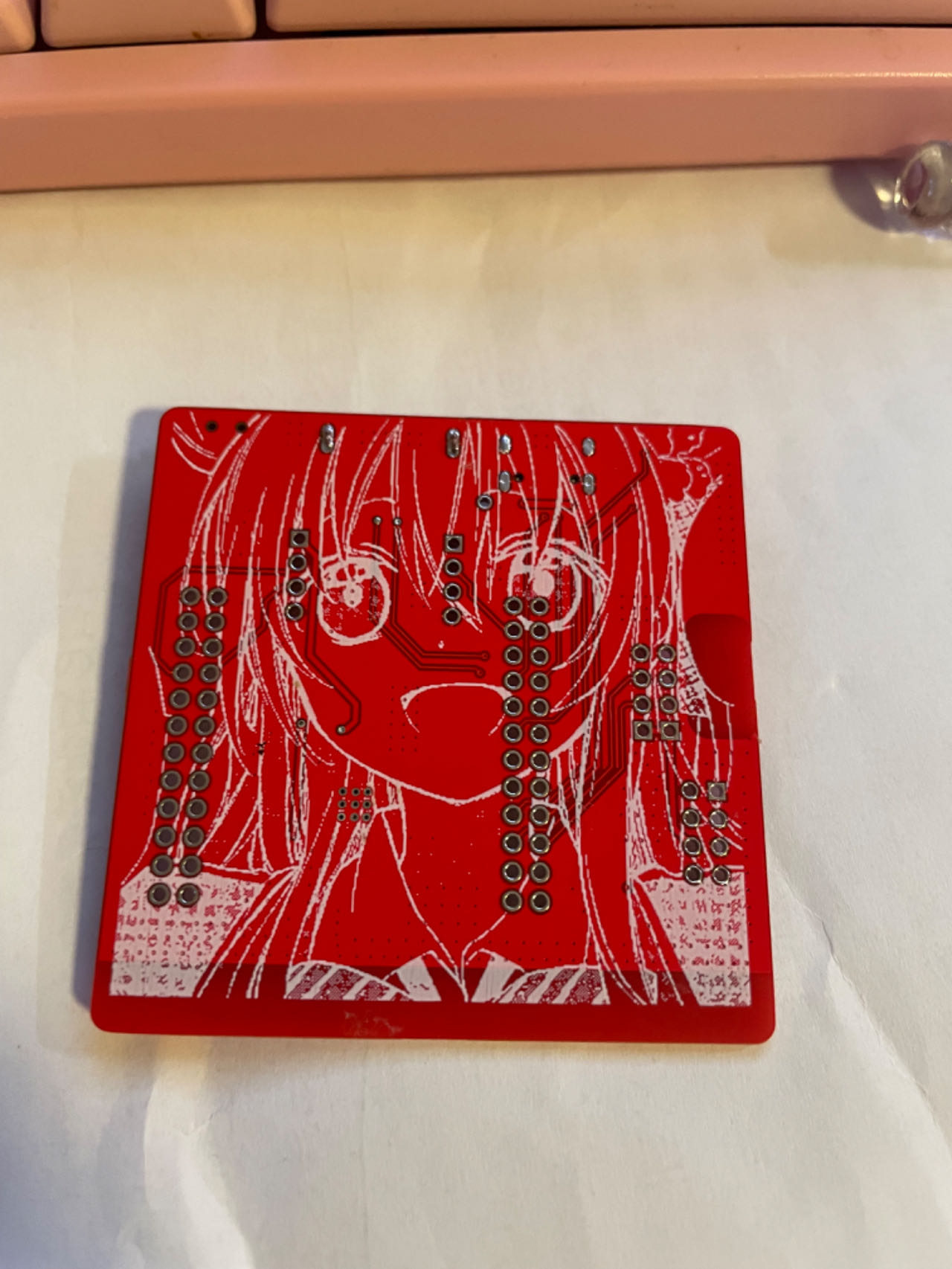
white rendering effect.


Chip
Introduction :
The CH583 is a 32-bit RISC microcontroller with integrated BLE wireless communication. The chip integrates a rich array of peripheral resources, including a 2Mbps Bluetooth Low Energy (BLE) communication module, two full-speed USB host and device controllers and transceivers, two SPIs, four serial ports, an ADC, a touch button detection module, and an RTC. The CH582 lacks one SPI1 compared to the CH583. The host and other components are identical.
Application block diagram.

Product features:
32-bit RISC processor (Qingke V4A)
, supports RV32IMAC instruction set, supports hardware multiplication and division;
32KB SRAM, 512KB Flash, supports ICP, ISP, and IAP, supports OTA wireless upgrades
; built-in 2.4GHz RF transceiver and baseband and link control, supports BLE 5.3;
supports 2Mbps, 1Mbps, 500Kbps, and 125Kbps
receiver sensitivity -98dBm, programmable +7dBm transmit power ;
provides protocol stack and application layer API;
built-in temperature sensor;
built-in RTC, supports both timed and trigger modes;
provides two USB 2.0 full-speed Host/Device ports
; provides 14-channel touch buttons;
provides a 14-channel 12-bit ADC;
provides four UARTs, two SPIs, 12 PWM channels, and one IIC channel.
It features 40 GPIOs, 4 of which support 5V signal input and
a minimum power supply voltage of 1.7V. It also includes
a built-in AES-128 encryption/decryption unit. The chip's unique ID
is QFN48. For more information, please refer to the development guide on
the Qinheng official website . This article shares some experience based on my recent research on this chip. Qinheng chips can use the officially recommended IDE, MounRiver Studio, but unfortunately, it doesn't support Mac OS, so I can't use it. You can use VS Code with PlatformIO for development, supporting the Arduino framework (arduino-wch58x), or you can write your own CMake build scripts. For example, see https://github.com/mo10/ch58x-cmake-template, and then use OpenOCD for simulation and debugging. However, it's important to note that although the two-wire simulation interface looks similar to the ARM Cortex-M series, common debuggers such as JLINK, STLINK, and DAP-LINK are incompatible. You need to purchase the dedicated debugger WCH-Link. There are several types of WCH-Link available, so be careful when choosing. WCH-LinkE is recommended here. For more information on debuggers, please refer to the official website: https://www.wch.cn/products/WCH-Link.html. Furthermore, manually opening debug mode using the ISP tool every time you debug is inconvenient. Downloading programs can be done via USB or serial port; USB download is more convenient. The download tool is wchISPtool, which can be downloaded from the attachments or the official website. However, WCHISPTool is only available for Windows. For Linux or Mac OS, you can use a third-party tool: https://github.com/ch32-rs/wchisp. If you don't want to compile, you can directly download the corresponding system package from the project's release and run it. Regarding hardware debugging :** Some shops on Taobao sell fake chips that cannot be recognized by the ISP tool after soldering, and the official chips are not available for sale. To enable the ISP tool to recognize the chip when using USB programming, press and hold the "Download" button on the evaluation board, or short PB22 to GND while powering on the board. If it's the first time you receive the chip, the codeflash will be empty, and the ISP tool will recognize it without pressing the "Download" button. If you encounter USB programming errors, first check if the programming environment is normal: ① Check the soldering: ensure the GND pin of the chip has been properly soldered, and check for cold solder joints or missing solder joints on PB10 and PB11. ② Check the power supply: ensure the voltage on the VINTA pin of the 57x and 58x chips is within the range of 1.05±0.015V, and the VINTA of the 208 is around 1.2V. ③ Check if the 32MHz crystal oscillator is oscillating; a normal 32MHz crystal oscillator is necessary for the normal operation of all chip modules. ④ Check the USB cable: test the cable to see if it can successfully program the evaluation board or other known-to-be-normal boards. Some cables do not have D+ and D- signal lines; do not use such cables. ⑤ Check if PB22 is brought out as the download configuration pin; PB22 needs to be grounded upon power-up to enter the bootloader. ⑥ Check if multiple ISP tools are open; the chip may have been recognized in other windows. ⑦ Check if the download configuration pin has been changed to PB11. If you accidentally modify PB11, you need to connect PB11 to v33. After powering on, quickly disconnect PB11 from v33 to re-enter the bootloader and modify the download configuration pin. If you frequently need to switch between PB22 and PB11, or if the project itself uses the USB1 interface as a download port and requires PB11 as the download configuration pin, you can connect a pull-up resistor of at least 1.5K (e.g., 10K) and a button to v33. Pressing the button will connect this pull-up resistor to PB11. This way, the built-in 1.5K pull-down resistor of the USB interface is relatively strong and will not affect USB communication after power-on boot recognition, saving one GPIO on PB22. If the burning environment is fine, observe whether the computer displays a prompt when the board is connected to the computer via USB. ① If the computer displays a prompt indicating excessive current: check if the GND and VCC pins of the USB port on the board are reversed, if there are short circuits on the board, or if any components are damaged.
② If the computer displays a message indicating that the chip cannot be recognized: Check if PB10 and PB11 are connected incorrectly, if there is interference or a short circuit to other pins, and if unnecessary strong pull-up/pull-down resistors or capacitors have been added. For USB programming issues, test with both pins floating first. If there are special requirements, add circuitry to check for compatibility. If the project uses USB1, be sure to disconnect other hosts/devices from the USB1 port.
③ If the computer does not display a message: Check if PB10 and PB11 are short-circuited. Cables are usually male at both ends. Connect the USB female port on the board to the A female port and check if the D+ and D- lines on the A female port are short-circuited.
⚠️ Note that some shops on Taobao sell counterfeit chips; you need to verify this yourself. If you are interested, you can apply for a development board from the official website; approval depends on luck.
If you want to make a product, you can buy one with high sales volume and many reviews on Taobao.
References and thanks to:
Troubleshooting USB programming for Qinheng Bluetooth series chips: https://www.cnblogs.com/JayWellsBlog/p/16934725.html;
wchisp: https://github.com/ch32-rs/wchisp;
arduino-wch58x: https://github.com/ElectronicCats/arduino-wch58x
; ch58x-cmake-template: https://github.com/mo10/ch58x-cmake-template;
CH573, CH579, and CH582 programming instructions: https://www.cnblogs.com/risc5-ble/p/16865626.html
WCHISPTool_Setup.exe
CH583DS1.pdf
CH583EVT (1).zip
PDF_ch582m development board - Sugar version.zip
Altium_ch582m Development Board - Sugar Version.zip
PADS_ch582m Development Board - Sugar Version.zip
BOM_ch582m Development Board - Sugar Version.xlsx
97324
8*8ws2812bdis
The author did this for fun.
A character display is created using 64 WS2812B LEDs in an 8x8 dot matrix.
VID_20231103_193356.mp4
IMG_20231103_192747.HEIC
IMG_20231103_192713.HEIC
IMG_20231103_192741.HEIC
PDF_8_8ws2812bdis.zip
Altium_8_8ws2812bdis.zip
PADS_8_8ws2812bdis.zip
BOM_8_8ws2812bdis.xlsx
97325
ESP8266-12F
Since there was no breadboard available, I designed a 12F small system board instead.
none
PDF_ESP8266-12F.zip
Altium_ESP8266-12F.zip
PADS_ESP8266-12F.zip
BOM_ESP8266-12F.xlsx
97326
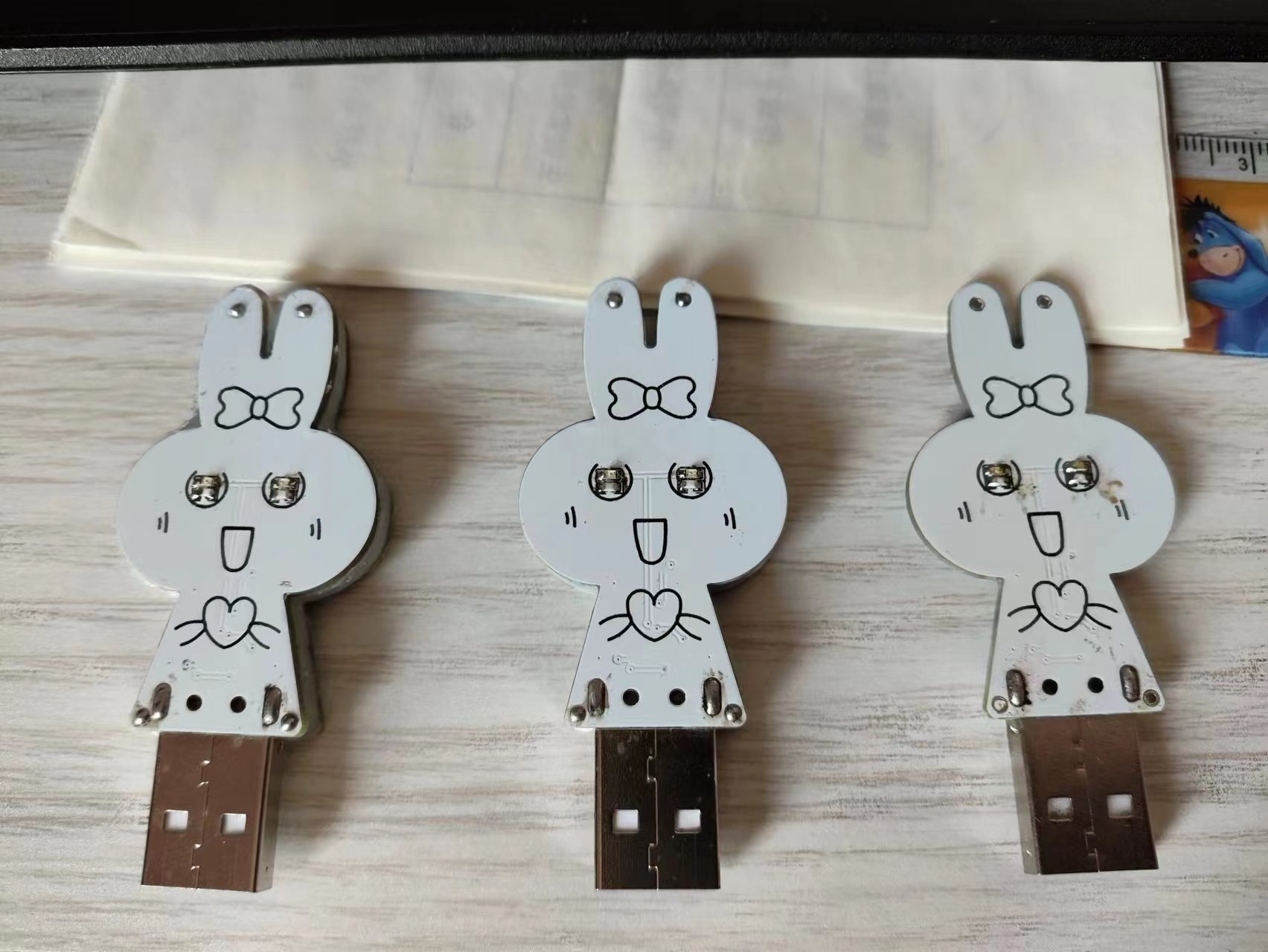
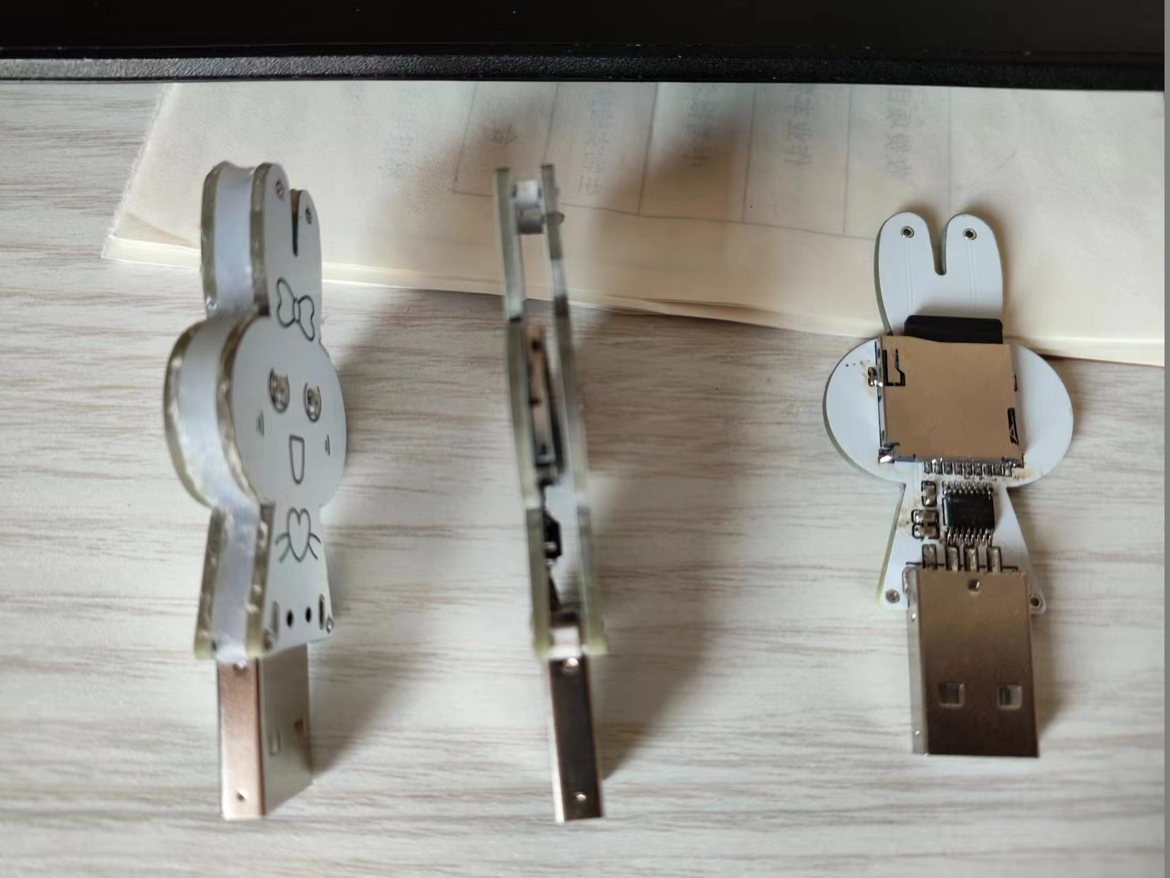
The little rabbit USB flash drive (actually a card reader)
The little rabbit USB flash drive (actually a card reader)
The little rabbit USB drive (actually a card reader) is quite fun.
WeChat_20231104091239.mp4
PDF_Little Rabbit USB Flash Drive (actually a card reader).zip
Altium_Little Rabbit USB Flash Drive (actually a card reader).zip
PADS_Little Rabbit USB Flash Drive (actually a card reader).zip
BOM_Little Rabbit USB Flash Drive (actually a card reader).xlsx
97331
Portable radio
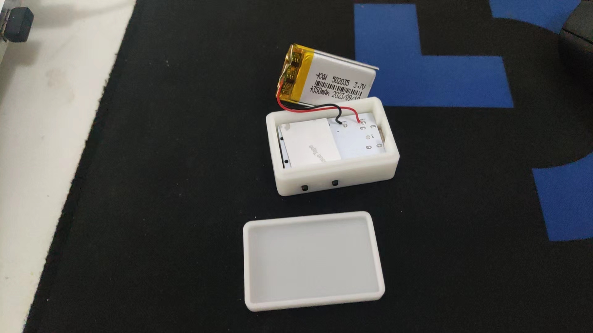
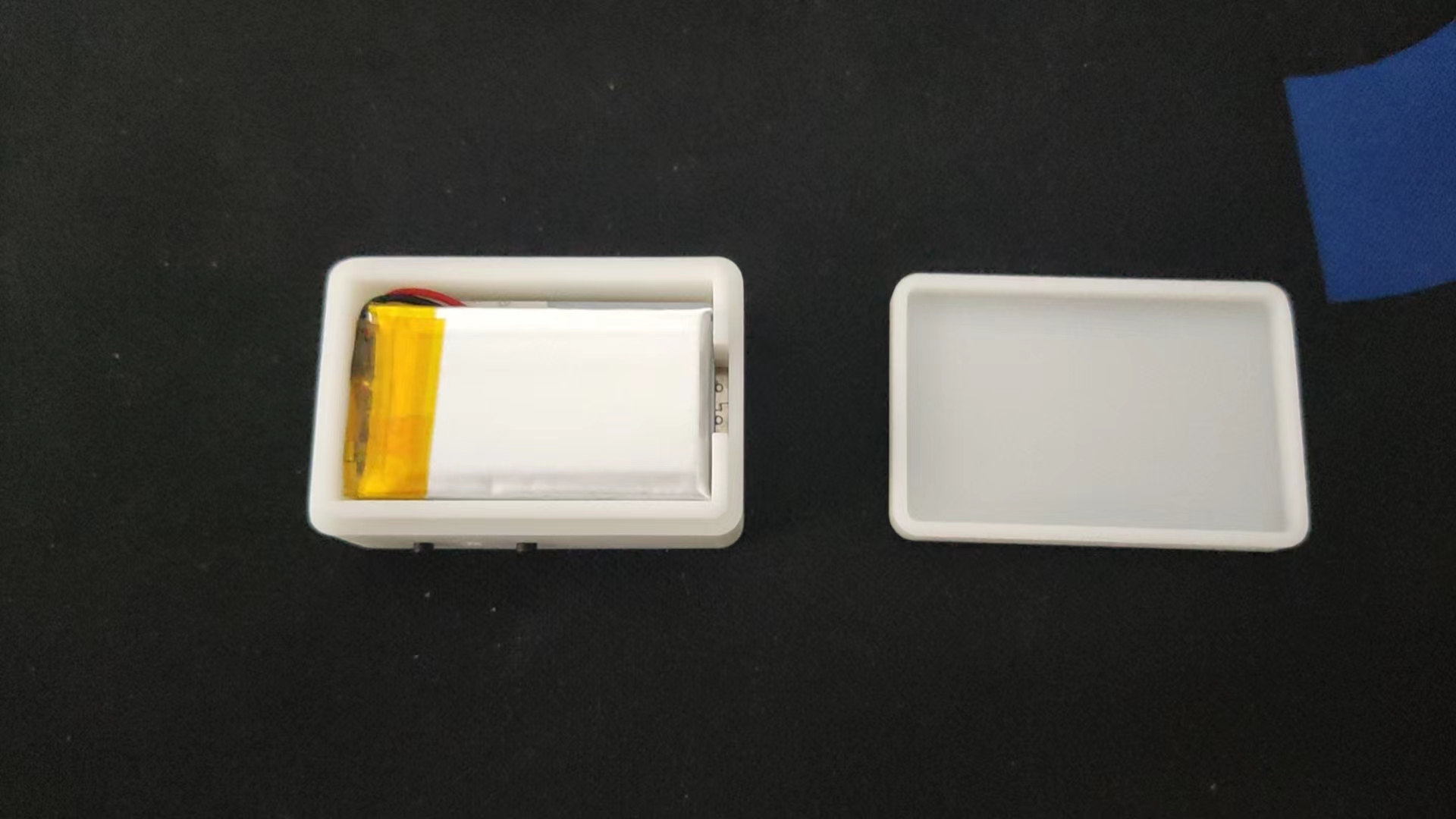
Portable Rechargeable Radio Made by RDA5807FP
The radio uses a TP4059 to charge the lithium battery and an XC6206P332MR for step-down power. It features a headphone jack with a switch for automatic power-on when headphones are plugged in. The 320mAh lithium battery provides over 10 hours of battery life.
3D casing instructions: It fits a 502035 polymer lithium battery perfectly. Buttons must be soldered during casing assembly; otherwise, they won't fit.

3DShell_PCB_300MA_3D.zip
PDF_Portable Radio.zip
Altium_Portable Radio.zip
PADS_Portable Radio.zip
BOM_Portable Radio.xlsx
97335
Audio 1-to-4 Electronic Switcher - PT2314
Audio 1-to-4 Electronic Switcher - PT2314
PT2314 4-Channel Audio Electronic Switcher -
1. Introduction:
The PT2314 is an IIC-controlled 4-channel analog audio electronic switcher with volume control.
It has a 9V power supply, which is somewhat inconvenient; a 5V boost circuit and microcontroller control can be added
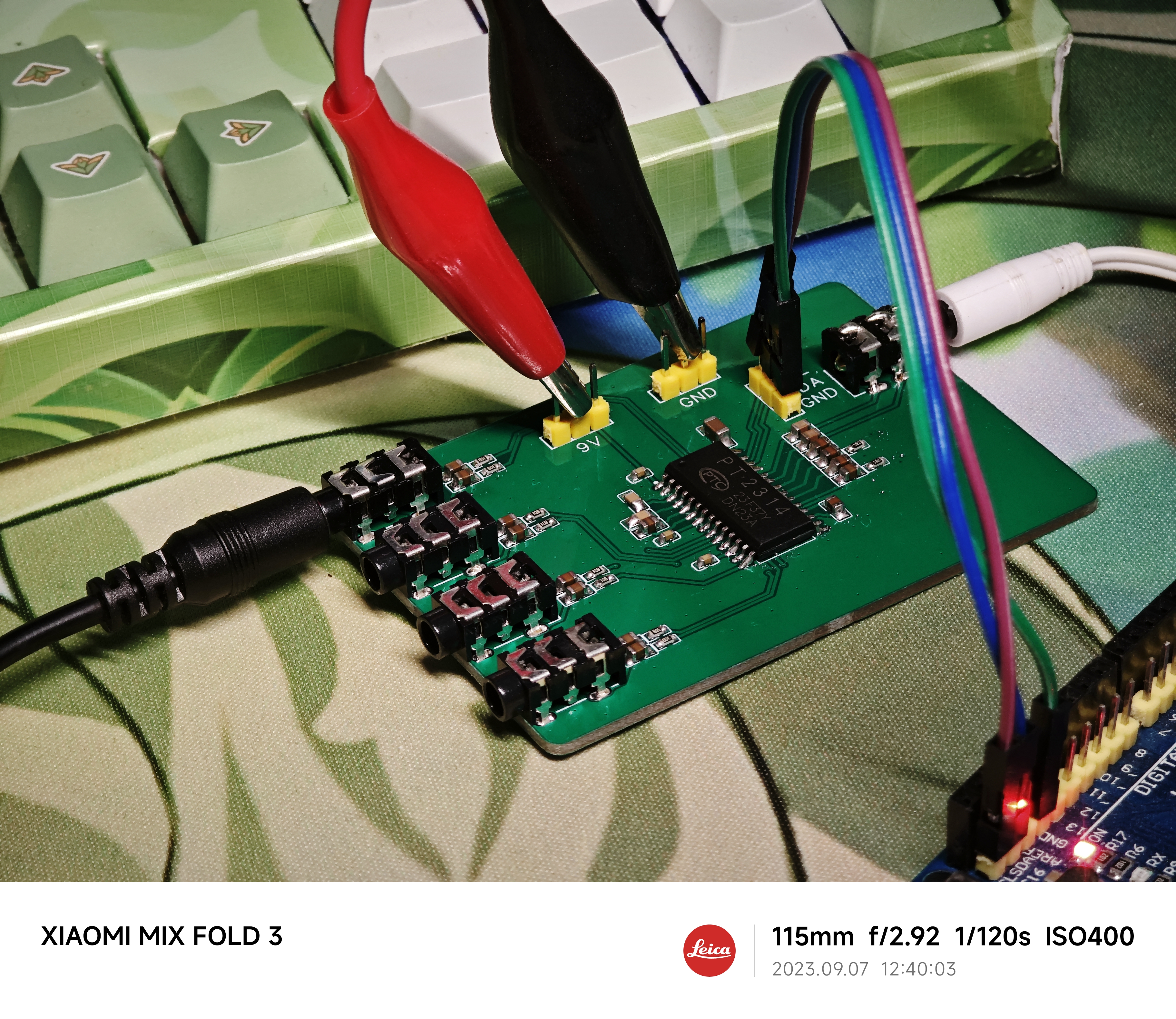
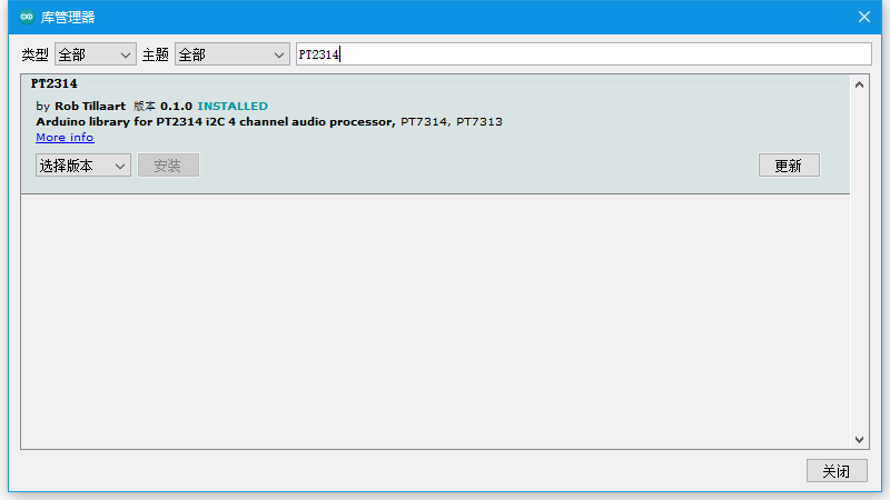
. 2. Code:
An existing library is available on the Arduino platform and can be used directly.
`pt.setChannel()` sets the switching channel;
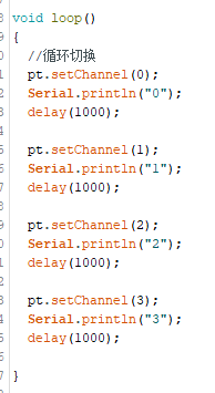
here, the volume is set.

PT2314 pdf, PT2314 Description, PT2314 ...pdf
PT2314_demo.zip
PDF_Audio 1-to-4 Electronic Switcher - PT2314.zip
Altium Audio 1-to-4 Electronic Switcher - PT2314.zip
PADS Audio 1-to-4 Electronic Switcher - PT2314.zip
BOM_Audio 1-to-4 Electronic Switcher - PT2314.xlsx
97337
310 heated bed, 220V aluminum substrate heating, 3D printing /tt/gugubot
Suitable for modifying 310 heated beds (240mm hole spacing) with 220V aluminum substrate heated beds, such as those used in DIY 3D printers like Gugubot, Dayu TT, and Dayu CC.
This is suitable for modifying 310 heated beds (240mm hole spacing), such as DIY 3D printers like those from Gugubot, Dayu TT, and Dayu CC. These printers, in order to control costs, all use 24V DC heated beds, resulting in very slow temperature rise, which can be quite frustrating for impatient users. 220V silicone heating pads truly offer superior heating performance; this open-source aluminum substrate heating pad completely outperforms silicone heating pads.
Each aluminum substrate has a trace length of 9.2m and a thickness of 0.035mm (1 ounce). Nine aluminum substrates are connected in series to a 220V power supply. Theoretical and measured power: [
Table showing trace width , resistance
per substrate,
theoretical power (9 substrates in
series), measured power (9 substrates in series)]
0.5mm
10 ohms
584
541
0.6mm
7.7 ohms
701
649
0.65mm
6.7 ohms
759
703
0.7mm
6.3 ohms
818
757

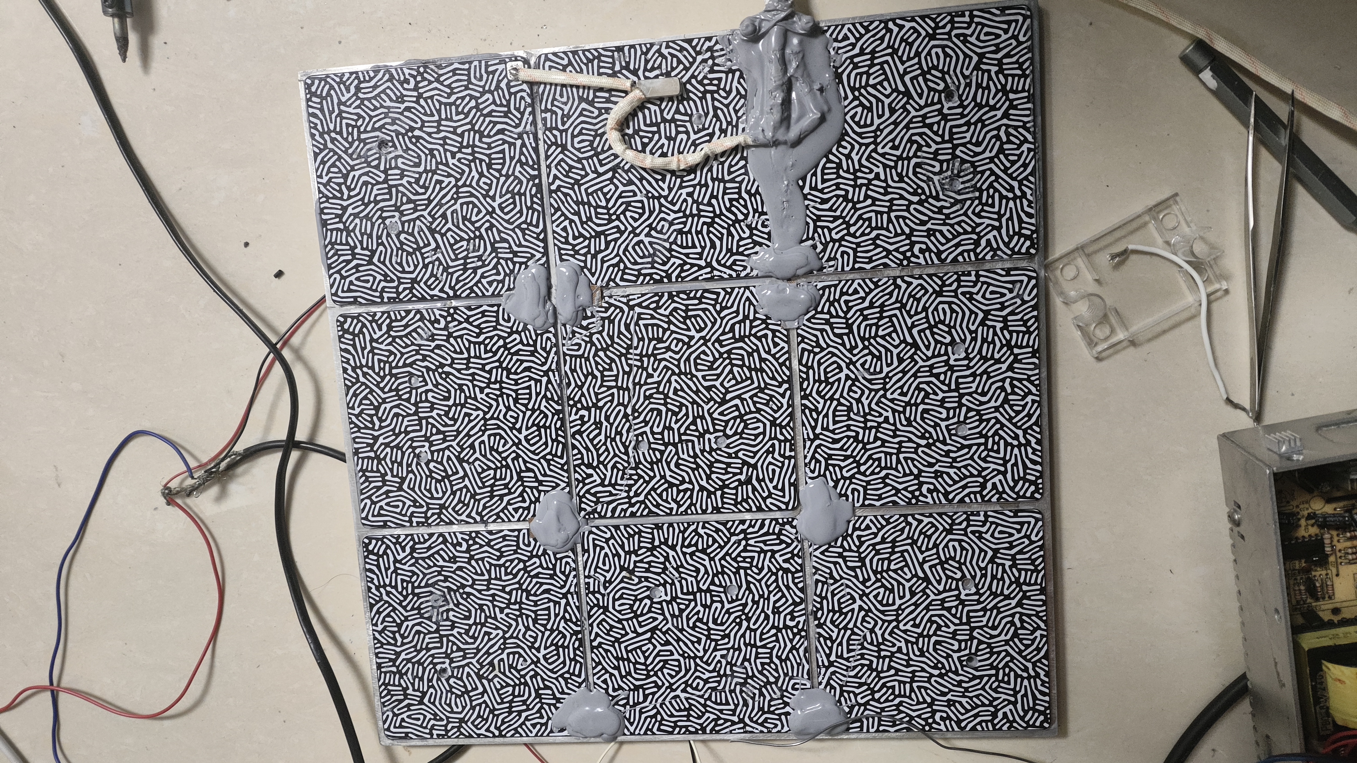
All nine substrates must be connected in series and properly insulated before connecting to the 220V power supply.
The connection method is shown in the diagram below. Ensure proper insulation and cover exposed solder joints with thermally conductive silicone (two tubes are sufficient).
Similarly, use thermally conductive silicone to attach the aluminum substrates and heated bed to the positions shown in the diagram below. (The heated bed can be a previous 24V heated bed, or you can buy a 310*310*8 aluminum plate and drill 240*240mm holes yourself; the cost is around 70).

The PCB includes pads for a 100k thermistor, allowing direct soldering of a 0603 thermistor
for 220V connection. This can be connected in series with a normally closed 120°C temperature switch to prevent overheating and potential fires.

Tested and proven stable and reliable with impressive temperature rise. 0.6mm trace width is recommended (this is the default PCB and PCB design file). Two types of PCBs are available; you can get 5 of each for free (the ones with screw holes are convenient for mounting on a heated bed).
**Important:** Ensure proper insulation and implement leakage protection measures!
ProProject_310 heated bed 220V aluminum substrate heating, 3D printing_tt_gugubot_2023-11-05.epro
Gerber_No Pre-drilled Holes_2023-11-05 0.6mm Line Width.zip
Gerber_Pre-drilled Screw Hole Positions_2023-11-05 0.6mm Line Width.zip
Hilbert curve (without chamfer).dwg
PDF_310 heated bed, 220V aluminum substrate heating, 3D printing - tt-gugubot.zip
Altium 310 heated bed, 220V aluminum substrate heating, 3D printing_tt_gugubot.zip
PADS_310 heated bed 220V aluminum substrate heating, 3D printing_tt_gugubot.zip
97338
esp32s3_clock
ESP32S3 Watch Screen Development Board V1
It's very thick, very thick, very thick!!
This is a test version; it's not recommended to install it.
PDF_esp32s3_clock.zip
Altium_esp32s3_clock.zip
PADS_esp32s3_clock.zip
BOM_esp32s3_clock.xlsx
97339
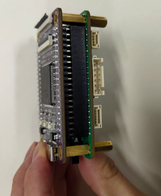
CH334R_UBS2.0
Based on the Chinheng CH334R USB 2.0 four-port USB hub control chip, plus the SY6280 programmable current limiting chip, the computer power supply is protected from overcurrent and short circuits.
Problem Description:
Most commercially available hubs are essentially pre-installed with a USB-A or Type-C cable, which significantly hinders their functionality, limiting their placement to very close to computer ports. My goal is to create a hub that can be placed anywhere I want, provided there's a long enough cable.
The desired functionality includes:
Type-C input ,
one Type-C female connector to four USB-A female connectors
, overcurrent and short-circuit protection (programmable current limiting settings),
power indicator
, and a beautifully designed, color-screened shell .
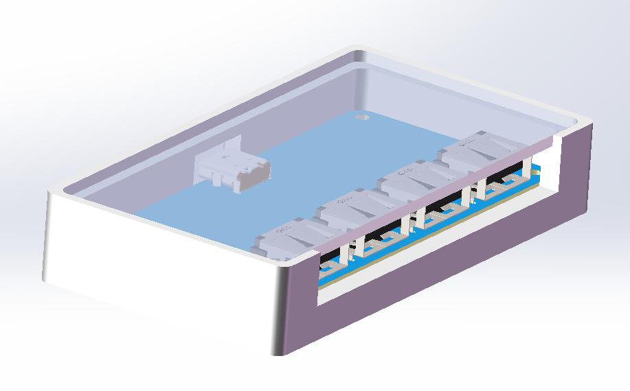
The shell design
uses a three-layer structure with a 3D-printed outer casing to maximize the beauty of the color screen printing. The top and bottom panels are transparent, with a color-screened PCB sandwiched in between, and finally covered by the 3D-printed shell. The main structural components, input and output structures, were exported from EDA professional software (the shell wasn't fully exported during verification due to the small computer). The main drawings are of the top and bottom panels and the shell. You can directly use "shell.STL" and "assembly.SLDASM" for their assembly. You can see the final effect; download the compressed file if you want to modify it. You can add patterns and various colors to the panel yourself. Remember to adjust the transparency so that the colored silkscreen printing inside isn't completely covered, losing its bright and shiny appearance and being buried in the casing and panel.

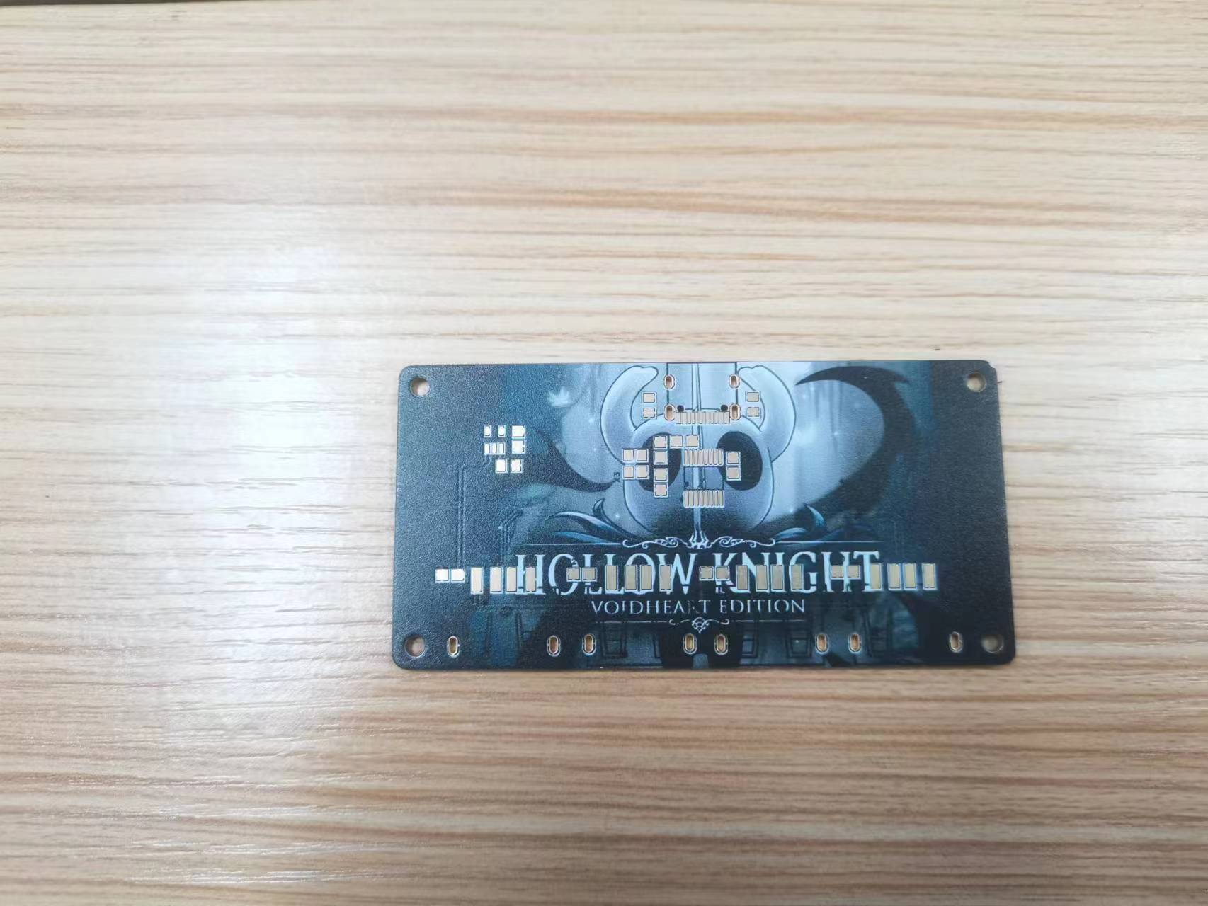
The photos of the colored silkscreen printing can be changed to your liking. As the saying goes, USB 2.0 generally works as long as it's connected, but I've opted for a ground plane enclosure because it's colored silkscreen printing. Since it's inside the casing, both sides need to be exposed so you can see both sides. To accommodate four USB-A ports and a small, non-compressed colored silkscreen printing sheet, the board is designed to be quite spacious. All resistors and capacitors use 0805 packages for easy soldering (Type-C and chips are slightly more difficult to solder). I forgot to add indicator lights during the PCB fabrication process, so there are no indicator lights in the physical demonstration (indicator lights are added in the actual project).
CH334DS1.PDF
3D-USB2.0.zip
Shell.STL
PDF_CH334R_UBS2.0.zip
Altium_CH334R_UBS2.0.zip
PADS_CH334R_UBS2.0.zip
BOM_CH334R_UBS2.0.xlsx
97340
electronic


 京公网安备 11010802033920号

 MQF20-208-3200-06


