I. Design Overview
With the development of technology, smart homes have become a trend. Smart curtains, as an important part of this trend, provide automation and convenience. This project aims to design and implement a smart curtain system based on the Liangshan School, so that the opening and closing of the curtains can be completed automatically according to the user's needs, improving the quality of life and user experience.
II. Introduction of each module
(1) Voice module
HLK-V20 The voice module is used to provide users with a user-friendly interactive experience. HLK-V20 supports offline recognition of 150 local commands, and HLK-V20S supports offline recognition of 50 local commands. The wake word, command word and response broadcast word can be freely customized, and it has rich peripheral interfaces. The voice recognition module can be freely designed by us and can be configured through the online configuration platform. After the configuration is completed, a voice recognition firmware will be generated. We need to download the firmware to the module and download it through the B6 and B7 pins of the module. Therefore, the B6 and B7 pins are brought out through the pin header to facilitate our download. It should also be noted that when downloading the firmware, the module must be powered off first. After the download tool recognizes the module, the module is powered on again so that it can be downloaded normally. This power-on/off operation is controlled by the SW1 switch in the schematic diagram.
HLK-V20 voice module firmware creation and download: http://voice.hlktech.com/yunSound/public/toWebLogout
http://www.smartpi.cn/#/
Port connection is as follows:
VDD --> 5V
B2 --> PA3
B3 --> PA2
GND --> GND

(2) Photosensitive sensor module
The working principle of the photoresistor is based on the internal photoelectric effect. The stronger the light, the lower the resistance. As the light intensity increases, the resistance value decreases rapidly, and the resistance value can be as low as below 1KΩ. The photoresistor is very sensitive to light. When there is no light, it is in a high resistance state. The special properties of the photoresistor will be widely used with the development of science and technology. We can judge the current light intensity by reading the resistance value of the photoresistor.

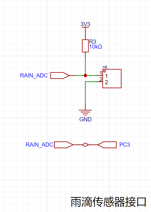
(3) Raindrop Sensor Module A
raindrop sensor is a sensing device mainly used to detect whether it is raining and the amount of rain. When the raindrop sensor detects raindrops, its resistance value will change. We can determine whether there is rain by obtaining its resistance value. We need to connect one pole of the raindrop sensor to positive and the other to negative in order to generate a circuit to measure the voltage change. However, when there are too many raindrops on the sensor, it will cause the two poles to be completely short-circuited. In order to prevent the raindrop sensor from being completely short-circuited, a resistor R1 needs to be added as a load to prevent 3.3V from being directly connected to GND, forming a power supply short circuit.
The port connection is as follows:
RAIN_ADC --> PC3
(4) Infrared Receiver Module
Infrared light is emitted in the form of pulses at a specific frequency. After the receiver receives the signal, it decodes it according to the agreed protocol to complete the data transmission. Principle of the receiver: The chip of the receiver is sensitive to this infrared light. It can output high and low levels according to whether there is light. If the flashing frequency of the transmitter is regular, the high and low levels output by the receiver are also regular. As long as the transmitter and receiver agree, data transmission can be performed. The NEC protocol uses pulse intervals to encode each bit of data, using the time interval of different data bits to represent different logic bits. It is very similar to the communication method of many single-bus ICs. The data is received by receiving the infrared light sent by the remote control. When the infrared light is received, the OUT pin will be pulled low. The GD32 can receive the data through the interrupt method. In this project, the GD32 is connected to the OUT pin of the infrared receiver through PF8.

(5) The stepper motor drive module
L9110S is a DC motor drive circuit. This product provides an integrated DC motor drive circuit for battery-powered toys, low-voltage or battery-powered control applications. It integrates an H-bridge drive circuit with MOS transistor design and is mainly used to drive general DC motors. It is used to drive the operation of the curtain motor. Two drive chips drive one motor. This project uses GD32 with PG12 and A_FOR, PG10 and A_BAK, PB9 and B_FOR, PB6 and B_BAK and motor chip
motor purchase link: https://item.taobao.com/item.htm?spm=a1z09.2.0.0.4be02e8dpoBqfX&id=642594293054&_u=72t4uge55e33

III. Main code
(1) Main function
int main(void)
{
nvic_priority_group_set(NVIC_PRIGROUP_PRE2_SUB2); // Priority grouping
// Tick timer initialization 1us
systick_config();
// Serial port 0 initialization debugging
usart_gpio_config(9600U);
// Voice recognition module pin initialization
hlk_usart_init(9600U);
// Raindrop and light recognition pin initialization
raindrop_and_light_config();
//Infrared receiver pin initialization
infrared_goio_config();
//Stepper motor initialization
stepper_motor_config();
stepper_motor_timer_config();
//Stepper motor reset
curtain_reset();
while(1)
{
//Voice command recognition operation: curtain control and mode switching
voice_anakysis_data();
//Infrared command recognition operation: curtain control and mode switching
infrared_command_judgment();
//Mode selection and corresponding mode operation
mode_select();
}
}
(2) Raindrop and light functions
#include "bsp_adc.h"
void raindrop_and_light_config(void)
{
//Enable pin clock
rcu_periph_clock_enable(BSP_RAINDROP_GPIO_RCU);
`rcu_periph_clock_enable(BSP_LIGHT_GPIO_RCU);
` // Enables the ADC clock.
`rcu_periph_clock_enable(BSP_ADC_RCU) ;
` // Configures the ADC clock
. `adc_clock_config(ADC_ADCCK_PCLK2_DIV4);
` // Configures the pins for analog input mode.
`gpio_mode_set(BSP_RAINDROP_GPIO_PORT, GPIO_MODE_ANALOG, GPIO_PUPD_NONE, BSP_RAINDROP_GPIO_PIN);`
`gpio_mode_set(BSP_LIGHT_GPIO_PORT, GPIO_MODE_ANALOG, GPIO_PUPD_NONE, BSP_LIGHT_GPIO_PIN);
` // Configures the ADC for standalone mode. `
adc_sync_mode_config(ADC_SYNC_MODE_INDEPENDENT);
` // Enables scan mode.
`adc_special_function_config(BSP_ADC, ADC_SCAN_MODE, ENABLE);`
// Right-align data
adc_data_alignment_config(BSP_ADC, ADC_DATAALIGN_RIGHT);
// Set ADC0 to 12-bit resolution
adc_resolution_config(BSP_ADC, ADC_RESOLUTION_12B);
// Set ADC0 to use 1 channel for the rule group
adc_channel_length_config(BSP_ADC, ADC_REGULAR_CHANNEL, 1);
// Disable external ADC triggering, i.e., only software triggering is allowed
adc_external_trigger_config(BSP_ADC, ADC_REGULAR_CHANNEL, EXTERNAL_TRIGGER_DISABLE);
// Enable ADC0
adc_enable(BSP_ADC);
// Enable ADC self-calibration
adc_calibration_enable(BSP_ADC);
}
unsigned int get_adc_value(uint8_t adc_channel_x)
{
unsigned int adc_value = 0;
// Set the acquisition channel
adc_regular_channel_config(BSP_ADC, 0, adc_channel_x, ADC_SAMPLETIME_15);
// Start software conversion
adc_software_trigger_enable(BSP_ADC, ADC_REGULAR_CHANNEL);
// Wait for ADC sampling to complete
while ( adc_flag_get(BSP_ADC, ADC_FLAG_EOC) == RESET )
{
;
}
// Read the sampled value
adc_value = adc_regular_data_read(BSP_ADC);
// Return the sampled value
return adc_value;
}
(3) Stepper motor drive function
#include "bsp_stepper_motor.h"
#include "systick.h"
#include "stdio.h"
#include "math.h"
uint8_t phasecw[8] = {0x08, 0x0c, 0x04, 0x06, 0x02, 0x03, 0x01, 0x09};
uint8_t phaseccw[8] = {0x09, 0x01, 0x03, 0x02, 0x06, 0x04, 0x0c, 0x08};
uint8_t motor_cw_flag = 0;
uint8_t motor_ccw_flag = 0;
// Current step count
int step_count = 0;
// Maximum step count, each beat represents one step
// Actual test shows that the number of steps from the left end to the right end is 600
// Please adjust this parameter according to the maximum step count of your device
#define MAX_STEPS 600
void stepper_motor_timer_config(void)
{
/* The time of one cycle T = 1/f, the timing time time = T * period
Let the prescaler value be pre, the period be per
time = (pre + 1) * (per + 1) / /* psc_clk
*/
timer_parameter_struct timer_initpara; // Define the timer structure
/* Enable the clock */
rcu_periph_clock_enable(RCU_TIMER5); // Enable the timer clock
/* CK_TIMERx = 4 x CK_APB1 = 4x50M = 200MHZ */
rcu_timer_clock_prescaler_config(RCU_TIMER_PSC_MUL4); // Configure the timer clock
timer_deinit(TIMER5); // Reset the timer
/* Configure timer parameters */
timer_initpara.prescaler = 2000-1; // Clock prescaler value 0-65535
timer_initpara.alignedmode = TIMER_COUNTER_EDGE; // Edge alignment
timer_initpara.counterdirection = TIMER_COUNTER_UP; // Count up
timer_initpara.period = 200-1; // Period
timer_initpara.clockdivision = TIMER_CKDIV_DIV1; // Divider factor
timer_initpara.repetitioncounter = 0; // Repetition counter 0-255
timer_init(TIMER5,&timer_initpara); // Initialize the timer
/* Configure interrupt priority */
nvic_irq_enable(TIMER5_DAC_IRQn,1,2); // Set the interrupt priority to 3,2
/* Enable interrupts */
timer_interrupt_enable(TIMER5,TIMER_INT_UP); // Enable update event interrupts
/* Enable the timer */
timer_enable(TIMER5);
}
void stepper_motor_config(void)
{
rcu_periph_clock_enable(AP_RCU); // Enable the clock
rcu_periph_clock_enable(AM_RCU); // Enable the clock
rcu_periph_clock_enable(BP_RCU); // Enable the clock
rcu_periph_clock_enable(BM_RCU); // Enable the clock
/* Configure A+ push-pull output mode and pull-up mode */
`gpio_mode_set(AP_PORT,GPIO_MODE_OUTPUT,GPIO_PUPD_PULLUP,AP_PIN);
gpio_output_options_set(AP_PORT,GPIO_OTYPE_PP,GPIO_OSPEED_50MHZ,AP_PIN);
/* Configure A-push-pull output mode with pull-up mode */
gpio_mode_set(AM_PORT,GPIO_MODE_OUTPUT,GPIO_PUPD_PULLUP,AM_PIN);
gpio_output_options_set(AM_PORT,GPIO_OTYPE_PP,GPIO_OSPEED_50MHZ,AM_PIN);
/* Configure B+push-pull output mode with pull-up mode */
gpio_mode_set(BP_PORT,GPIO_MODE_OUTPUT,GPIO_PUPD_PULLUP,BP_PIN);`
gpio_output_options_set(BP_PORT,GPIO_OTYPE_PP,GPIO_OSPEED_50MHZ,BP_PIN);
/* Configure B-push-pull output mode and pull-up mode */
gpio_mode_set(BM_PORT,GPIO_MODE_OUTPUT,GPIO_PUPD_PULLUP,BM_PIN);
gpio_output_options_set(BM_PORT,GPIO_OTYPE_PP,GPIO_OSPEED_50MHZ,BM_PIN);
AP(0);
BP(0);
AM(0);
BM(0);
}
void motor_cw(void)
{
static uint8_t i=0;
// Enable clockwise motion
if( motor_cw_flag == 1 )
{
AP ( ( phasecw[i] >> 3 ) & 0x01 );
BP ( ( phasecw[i] >> 2 ) & 0x01 );
AM ( ( phasecw[i] ) >> 1 ) & 0x01 );
BM ( ( phasecw[i] >> 0 ) & 0x01 );
// Increase the number of steps
i = ( i + 1 ) % 8;
// Record the current step number
step_count++;
}
}
void motor_ccw( void )
{
static uint8_t i=0;
// If counter-clockwise motion is enabled
if( motor_ccw_flag == 1 )
{
AP ( ( phaseccw[i] >> 3 ) & 0x01 );
BP ( ( phaseccw[i] >> 2 ) & 0x01 );
AM ( ( phaseccw[i] >> 1 ) & 0x01 );
BM ( ( phaseccw[i] >> 0 ) & 0x01 );
i = ( i + 1 ) % 8;
// Record the current step count
if( step_count <= 1 ) step_count = 1;
step_count--;
}
}
void motor_stop( void )
{
AP ( 0 );
BP ( 0 );
AM ( 0 );
BM ( 0 );
}
void curtain_reset(void)
{
// If the step count has not reached the maximum step count
while( get_step_count() < MAX_STEPS )
{
// Stepper motor rotates clockwise, incrementing the step count
motor_cw_flag = 1;
motor_ccw_flag = 0;
}
// Stop the stepper motor
motor_cw_flag = 0;
motor_stop();
}
void open_curtain(void)
{
// If the step count has not reached 0 steps
if( get_step_count() > 0 )
{
// Stepper motor rotates counterclockwise, decrementing the step count
motor_ccw_flag = 1;
motor_cw_flag = 0;
}
else
{
// Stop the stepper motor
motor_ccw_flag = 0;
motor_cw_flag = 0;
motor_stop();
}
}
void close_curtain(void)
{
// If the step count has not reached the maximum step count
if( get_step_count() < MAX_STEPS )
{
// Stepper motor rotates clockwise, incrementing the step count
motor_cw_flag = 1;
motor_ccw_flag = 0;
}
else
{
// Stop the stepper motor
motor_cw_flag = 0;
motor_ccw_flag = 0;
motor_stop();
}
}
void limit_judgment(int num)
{
// If the current rotation is clockwise
if( motor_cw_flag == 1 )
{
// If the number of clockwise rotations has exceeded the maximum number of steps
if( num >= MAX_STEPS )
{
// Stop the rotation
motor_cw_flag = 0;
motor_stop();
}
}
// If the current rotation is counterclockwise
if( motor_ccw_flag == 1 )
{
// If the number of counterclockwise rotations has decreased to 0 steps
if( num <= 0 )
{
// Stop the rotation
motor_ccw_flag = 0;
motor_stop();
}
}
}
int get_step_count(void)
{
return step_count;
}
void set_step_count(int num)
{
step_count = num;
}
void TIMER5_DAC_IRQHandler(void)
{
/* This is the timer interrupt */
if(timer_interrupt_flag_get(TIMER5,TIMER_INT_FLAG_UP) == SET)
{
timer_interrupt_flag_clear(TIMER5,TIMER_INT_FLAG_UP); // Clear the interrupt flag
// Rotate
motor_cw() clockwise;
// Rotate
motor_ccw() counterclockwise;
}
}
(4) Infrared receiving function
#include "bsp_ir_receiver.h"
#include "bsp_usart.h"
#include "stdio.h"
#include "systick.h"
#include "bsp_mode_control.h"
#include "bsp_stepper_motor.h"
#include "bsp_voice.h"
typedef struct INFRARED_DATA{
uint8_t AddressCode; // Address code
uint8_t AddressInverseCode; // Address inverse code
uint8_t CommandCode; // Command code
uint8_t CommandInverseCode; // Command inverse code
}_INFRARED_DATA_STRUCT_;
// Infrared data structure
_INFRARED_DATA_STRUCT_ InfraredData;
void infrared_goio_config(void)
{
// Enable pin clock
rcu_periph_clock_enable(IR_RCU);
// Enable system configuration clock
rcu_periph_clock_enable(RCU_SYSCFG);
// Configure pin as pull-up input
gpio_mode_set(IR_PORT, GPIO_MODE_INPUT, GPIO_PUPD_PULLUP, IR_PIN);
/* Enable NVIC interrupts. Interrupt grouping is 2-bit preemption priority and 2-bit sub-priority */
`nvic_irq_enable(EXTI_IRQ,2U,2U); // Preemption priority 2, sub-priority 2
/* Connect interrupt line to GPIO */
syscfg_exti_line_config(EXTI_SOURCE_PORT,EXTI_SOURCE_PIN);
/* Initialize interrupt line falling edge trigger */
exti_init(EXTI_X,EXTI_INTERRUPT,EXTI_TRIG_FALLING);
/* Enable interrupt */
exti_interrupt_enable(EXTI_X);
/* Clear interrupt flag */
exti_interrupt_flag_clear(EXTI_X);
}
{
uint32_t time_val = 0;
while( gpio_input_bit_get(IR_PORT, IR_PIN) == 0 )
{
if( time_val>= 500 )
{
*low_time = time_val;
return;
}
delay_1us(20);
time_val++;
}`
*low_time = time_val;
}
void get_infrared_high_time(uint32_t *high_time)
{
uint32_t time_val = 0;
while( gpio_input_bit_get(IR_PORT, IR_PIN) == 1 )
{
if( time_val >= 250 )
{
*high_time = time_val;
return;
}
delay_1us(20);
time_val++;
}
*high_time = time_val;
}
uint8_t guide_and_repeat_code_judgment(void)
{
uint32_t out_time=0;
get_infrared_low_time(&out_time);
//time>10ms time <8ms
if((out_time > 500) || (out_time < 400))
{
return 1;
}
get_infrared_high_time(&out_time);
// x>5ms or x<2ms
if((out_time > 250) || (out_time < 100))
{
return 1;
}
//If it is a repeated code 2ms < time < 3ms
if((out_time > 100) && (out_time < 150))
{
return 2;
}
return 0;
}
uint8_t infrared_data_true_judgment(uint8_t *value)
{
// Check if the address code is correct
if ( value[0] != (uint8_t)(~value[1]) ) return 0;
// Check if the command code is correct
if ( value[2] != (uint8_t)(~value[3]) ) return 1;
printf("%x %x %x %x
",value[0],value[1],value[2],value[3]);
// Save the correct data
InfraredData.AddressCode = value[0];
InfraredData.AddressInverseCode = value[1];
InfraredData.CommandCode = value[2];
InfraredData.CommandInverseCode = value[3];
}
void receiving_infrared_data(void)
{
uint16_t group_num = 0,data_num = 0;
uint32_t time=0;
uint8_t bit_data = 0;
uint8_t ir_value[5] = {0};
uint8_t guide_and_repeat_code = 0;
// Wait for the guide code
guide_and_repeat_code = guide_and_repeat_code_judgment();
// If it's not the guide code, end the parsing
if( guide_and_repeat_code == 1 )
{
printf("err
");
return;
}
// There are 4 groups of data
// Address code + address complement + command code + command complement
for(group_num = 0; group_num < 4; group_num++ )
{
// Receive a group of 8-bit data
for( data_num = 0; data_num < 8; data_num++ )
{
// Receive low level
get_infrared_low_time(&time);
// If the low level is not within 0.56ms,Data error
if((time > 60) || (time < 20))
{
return;
}
time = 0;
// Receive high level
get_infrared_high_time(&time);
// If at 1200us=60) && (time < 100))
{
bit_data = 1;
}
// If at 200us=10) && (time < 50))
{
bit_data = 0;
}
//groupNum indicates which group of data
ir_value[ group_num ] <<= 1;
//The first received number is high level;In the second for loop, the data will be shifted 8 times to the right
ir_value[ group_num ] |= bit_data;
//After the time is used up, the value must be reassigned
time=0;
}
}
//Check if the data is correct, if correct, save the data
infrared_data_true_judgment(ir_value);
}
uint8_t get_infrared_command(void)
{
return InfraredData.CommandCode;
}
void clear_infrared_command(void)
{
InfraredData.CommandCode = 0x00;
}
void infrared_command_judgment(void)
{
//Play the voice of "Currently in automatic mode"
unsigned char auto_mode_report[5] = {0XAA, 0X55, 0X01, 0X55, 0XAA};
// Announce the message "Currently in manual mode"
unsigned char manual_mode_report[5] = {0XAA, 0X55, 0X02, 0X55, 0XAA};
// Announce the message "Curtains are open"
unsigned char curtain_open_report[5] = {0XAA, 0X55, 0X03, 0X55, 0XAA};
// Announce the message "Curtains are closed"
unsigned char curtain_clear_report[5] = {0XAA, 0X55, 0X04, 0X55, 0XAA};
// If the [*] key is pressed, enter automatic mode
if( get_infrared_command() == 0X68 )
{
clear_infrared_command();
set_mode_switch_flag(AUTO_MODE);
// Announce the message "Currently in automatic mode"
hlk_usart_send_string(auto_mode_report, 5);
}
// If the [#] key is pressed, enter non-automatic mode
if( get_infrared_command() == 0Xb0 )
{
clear_infrared_command();
set_mode_switch_flag(NO_AUTO_MODE);
// Announce "Currently in manual mode" voice
hlk_usart_send_string(manual_mode_report, 5);
}
// If the [<] key is pressed, close the curtains
if( get_infrared_command() == 0X10 )
{
clear_infrared_command();
close_curtain();
set_mode_switch_flag(NO_AUTO_MODE);
// Announce "Curtains are closed" voice
hlk_usart_send_string(curtain_clear_report, 5);
}
// If the [>] key is pressed, open the curtains
if( get_infrared_command() == 0X5a )
{
clear_infrared_command();
open_curtain();
set_mode_switch_flag(NO_AUTO_MODE);
// Announce the message "Curtains are open"
hlk_usart_send_string(curtain_open_report, 5);
}
}
void EXTI5_9_IRQHandler(void)
{
if(exti_interrupt_flag_get(EXTI_X) == SET) // Interrupt flag is 1
{
if(gpio_input_bit_get(IR_PORT,IR_PIN) == RESET) // If it is low
{
// Receive infrared data once
receiving_infrared_data();
}
exti_interrupt_flag_clear(EXTI_X); // Clear the interrupt flag
}
}
(5) Speech recognition function
#include "bsp_voice.h"
#include "stdio.h"
#include "string.h"
#include "bsp_stepper_motor.h"
#include "bsp_mode_control.h"
unsigned char hlk_rx_buff[HLK_RX_LEN_MAX];
unsigned char hlk_rx_flag = 0;
unsigned char hlk_rx_len = 0;
unsigned char rx_data = 0;
unsigned char rx_flag = 0;
void hlk_usart_init(unsigned int bund)
{
/* Enable the clock of HLK_USART */
rcu_periph_clock_enable(RCU_HLK_USART);
/* Enable the clock */
`rcu_periph_clock_enable(RCU_HLK_TX);
rcu_periph_clock_enable(RCU_HLK_RX);
/* Configure the pin for multiplexing */
gpio_af_set(PORT_HLK_TX, BSP_HLK_AF, GPIO_HLK_TX);
/* Configure the pin for multiplexing */
gpio_af_set(PORT_HLK_RX, BSP_HLK_AF, GPIO_HLK_RX);
/* Configure the TX pin for multiplexing pull-up mode */
gpio_mode_set(PORT_HLK_TX, GPIO_MODE_AF, GPIO_PUPD_PULLUP, GPIO_HLK_TX);
/* Configure the RX pin for multiplexing pull-up mode */
gpio_mode_set(PORT_HLK_RX, GPIO_MODE_AF, GPIO_PUPD_PULLUP, GPIO_HLK_RX);
/*` /* Configure PA2 pin to output mode */
gpio_output_options_set(PORT_HLK_TX, GPIO_OTYPE_PP, GPIO_OSPEED_50MHZ, GPIO_HLK_TX);
/* Configure PA3 pin to output mode */
gpio_output_options_set(PORT_HLK_RX, GPIO_OTYPE_PP, GPIO_OSPEED_50MHZ, GPIO_HLK_RX);
/* Set the baud rate of HLK_USART to 115200 */
usart_baudrate_set(HLK_USART, bund);
/* Set the parity bit of HLK_USART to none */
usart_parity_config(HLK_USART, USART_PM_NONE);
/* Set the data bits of HLK_USART to 8 bits */
usart_word_length_set(HLK_USART, USART_WL_8BIT);
/* /* Set the stop bit of HLK_USART to 1 bit */
usart_stop_bit_set(HLK_USART, USART_STB_1BIT);
/* Enable serial port 1 */
usart_enable(HLK_USART);
/* Enable HLK_USART transmission */
usart_transmit_config(HLK_USART, USART_TRANSMIT_ENABLE);
/* Enable HLK_USART receive */
usart_receive_config(HLK_USART, USART_RECEIVE_ENABLE);
/* Enable HLK_USART receive interrupt flag */
usart_interrupt_enable(HLK_USART, USART_INT_RBNE);
/* Enable HLK_USART idle interrupt flag */
usart_interrupt_enable(HLK_USART, USART_INT_IDLE);
/* Configure interrupt priority */
nvic_irq_enable(HLK_USART_IRQ, 2, 2);
}
void hlk_usart_send_bit(unsigned char ch)
{
// Send character
usart_data_transmit(HLK_USART, ch);
// Wait for the data to be sent buffer flag to be automatically set
while(RESET == usart_flag_get(HLK_USART, USART_FLAG_TBE) );
}
void hlk_usart_send_string(unsigned char *str, unsigned int str_len)
{
while( str_len-- ) // Exit if address is empty or value is empty
{
hlk_usart_send_bit(*str++);
}
}
void clear_hlk_rx_buff(void)
{
unsigned char i = HLK_RX_LEN_MAX-1;
while(i)
{
hlk_rx_buff[i--] = 0;
}
hlk_rx_len = 0;
hlk_rx_flag = 0;
}
unsigned char voice_anakysis_data(void)
{
unsigned char ret = 0;
if( rx_flag == 1 )// Receive voice command
{
rx_flag = 0;
switch( rx_data ) // Determine the corresponding action based on the voice command
{
case 0x01:// Open curtain command
open_curtain();
// Set non-automatic mode
set_mode_switch_flag(NO_AUTO_MODE);
break;
case 0x02:// Close curtain command
close_curtain();
// Set non-automatic mode
set_mode_switch_flag(NO_AUTO_MODE);
break;
case 0x03:// Automatic mode command
set_mode_switch_flag(AUTO_MODE);
break;
case 0x04:// Manual mode command
set_mode_switch_flag(NO_AUTO_MODE);
break;
}
ret = 1;
// Clear the current data
clear_hlk_rx_buff();
}
// Stepper motor limit judgment
limit_judgment(get_step_count());
return ret;
}
void HLK_USART_IRQHandler(void)
{
if(usart_interrupt_flag_get(HLK_USART,USART_INT_FLAG_RBNE) != RESET) // Receive buffer is not empty
{
// Receive data
hlk_rx_buff[ hlk_rx_len ] = usart_data_receive(HLK_USART);
#if DEBUG
// Test, check what data was received
printf("%c", hlk_rx_buff[ hlk_rx_len ]);
#endif
//0XAA X 0X55
if( hlk_rx_buff[hlk_rx_len] == 0X55 )//Received frame tail
{
if( hlk_rx_buff[hlk_rx_len-2] == 0XAA)//Received frame header, confirm data format is correct
{
rx_data = hlk_rx_buff[hlk_rx_len-1];//Received data
rx_flag = 1;
}
}
// Receive length limit
hlk_rx_len = ( hlk_rx_len + 1 ) % HLK_RX_LEN_MAX;
}
if(usart_interrupt_flag_get(HLK_USART,USART_INT_FLAG_IDLE) == SET) // Idle interrupt detected
{
usart_data_receive(HLK_USART); // Must read, the read value cannot be
hlk_rx_buff[hlk_rx_len] = ''; // String end padding
hlk_rx_flag = 1; // Reception complete
}
}
IV. Summary
(1) Innovations
1. Improved convenience: The curtains can be opened and closed directly by voice control, and the curtains can be in automatic or manual mode. In automatic mode, the user does not need to manually operate the curtains. The curtains will automatically close after a large number of raindrops are detected, and will automatically open after strong light, saving people a lot of energy to worry about opening and closing the curtains. In manual mode, the curtains can be remotely opened and closed by infrared remote control.
2. Light and raindrop sensing: Traditional smart curtains are mostly based on light sensing, while this project uses light sensors and raindrop sensors to realize the perception of outdoor light and raindrops. In this way, the smart curtains can automatically adjust their opening and closing according to the ambient light intensity and weather conditions, providing a more comfortable indoor environment.
(2) Experiences and insights
Due to a lack of knowledge in this project, the progress was slow. By reviewing materials and consulting with teachers and senior students, we adjusted the plan in a timely manner and spent some time learning relevant knowledge. In this process, we realized that the most important thing in the project is to grasp the main research problem. What I feel most deeply is that we must be diligent in thinking, be good at analyzing problems from different angles, find references and tutorials, find innovative directions, and keep thinking hard. We must prove the feasibility of the experiment step by step through practice. In the project, we continuously improved our technical skills and knowledge reserves.


 京公网安备 11010802033920号

 NJL5193K


