Introducing a Bluetooth case - a data transparent transmission application developed based on the MM32W series.
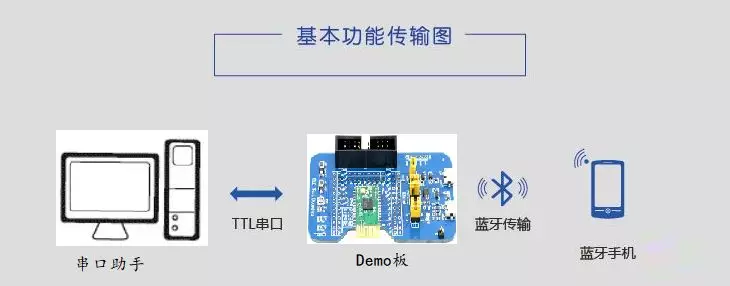
Speaking of how the low-power Bluetooth module works, it is indispensable to introduce the simplest and most common communication method in the low-power Bluetooth module - data transparent transmission. Transparent transmission is also called serial port transparent transmission, which means transparent transmission. Transparent transmission is a working method, not a function, and generally appears in serial port modules. In order to allow users to better develop Bluetooth wireless transmission products, the Smart MM32W series MCU does not need to worry about how to implement the internal Bluetooth protocol stack, and can quickly implement the functions of the serial port module. The specific working mechanism of the serial port module is that it does not do any processing on the data to be transmitted by the MCU , and does not need to add any protocols by itself. The user can control the size of the data packet and conduct bidirectional transmission between the APP .
Hardware resources are as follows:
This solution is tested and verified based on the MM32 BLE_Test Board , and a Micro usb data line is used as a carrier for communication with the host computer's serial port assistant. In terms of hardware principles, the Demo of this solution has a USB to serial port chip onboard, which is connected to the UART2 function pin of the MCU through a jumper cap. The RXD of the USB to serial port chip is connected to TX2 (PA2) , and TXD is connected to RX2 (PA3). on the communication pins, and LEDs of different colors are connected in parallel on the communication pins as an indication of data transmission and reception; use PB1 to connect to the green LED indicator light, which can be used as an indication of the Bluetooth connection status; the low-power wake-up pin selection PA0 is configured as Pull-up input; Bluetooth-related function pins are consistent with the previously introduced solution, so we will not expand too much here. The following is the USB-TTL serial port conversion schematic diagram:

Figure 2 Schematic diagram
Software resources are as follows:
Combined with the hardware resources used above, below we focus on the software implementation process and related configuration code. Since this application scheme uses transparent transmission of data between the BLE chip and the APP , in order to avoid interference from other data, the broadcast messages at the application layer are cancelled, and there is no need to set the pairing mode; since this scheme uses the UART2 of the MCU , when using printf When debugging the printing function, it is necessary to switch the serial port used internally by the two library functions fputc and fgetc to UART2 , and use the query mode to print data, which is different from the transparent transmission method in this case ( interruption mode); in addition, the connection The pins of the status indicator light are configured to more intuitively observe and verify the application effect, and the watchdog reset function is enabled to ensure the stable performance of the Bluetooth service; due to the need for low power consumption in the solution application, this solution Low power consumption adopts SLEEP and STOP dual mode switching, and enters different low power consumption modes according to different timeouts.
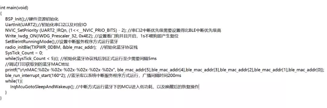
The following initializes the configuration content of the main function. It mainly initializes all peripheral resources and the Bluetooth protocol stack, and runs Bluetooth in the form of an interrupt service program. The main functions implemented in the loop of the main function are to determine whether to enter low-power mode, based on The serial port receives and sends data during the timeout period to enter the low-power mode. The code is as follows:
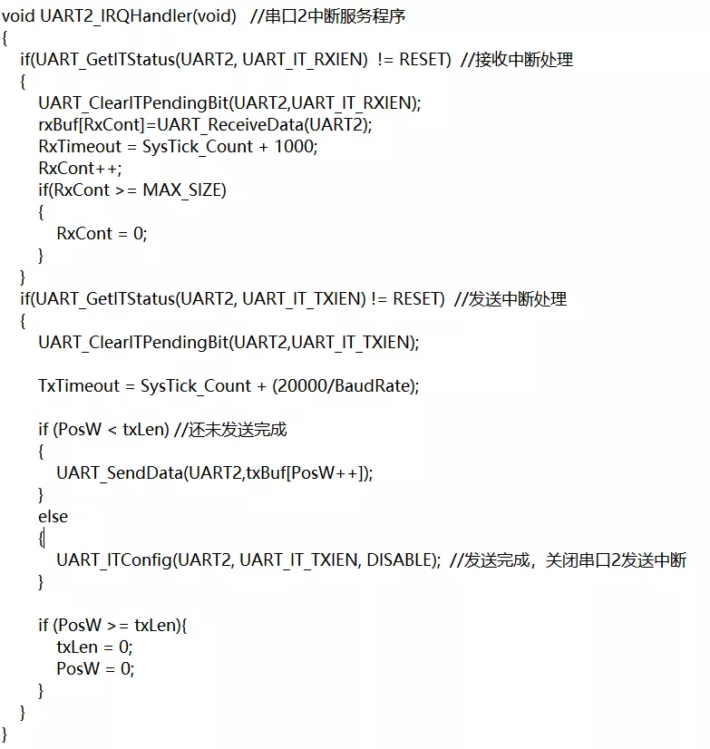
 The following focuses on several functions related to serial port 2 operations:
/*** Serial port 2 sending data interface. When the MCU receives the Bluetooth transparent transmission data, the program will call this interface function. This function mainly implements loading the data to be sent into the TX BUFF and waiting for the serial port interrupt service program to process and send ** */
void moduleOutData(u8*data, u8 len)
{
unsigned char i;
if ((txLen+len)<MAX_SIZE)// Sending BUFF without overflow
/*** Redefine the printf implementation library function, and use the POLLING method of UART2 to send data to avoid conflicts with transparent transmission ***/
int fputc(int ch, FILE *f)
{
UART_SendData(UART2, (uint16_t) ch);
while(1) {
if(UART_GetITStatus(UART2, UART_IT_TXIEN)) {
UART_ClearITPendingBit(UART2, UART_IT_TXIEN);
break;
}
}
return ch;
}
int fgetc(FILE *f)
while(1) {
/*** When receiving data from the serial port assistant, the interrupt service routine processes the received BUFF loading data, and calls this function in the periodic callback function of the Bluetooth protocol to send the serial port assistant data to the APP***/
void CheckComPortInData(void) //at cmd NOT supported
{
u16 send;
if(comrxbuf_wr_pos != comrxbuf_rd_pos)// receiving BUFF is not empty {
if(!GetConnectedStatus())// Bluetooth is not connected {
comrxbuf_rd_pos = comrxbuf_wr_pos; // Clear the receiving BUFF
}
else // Bluetooth connection is normal {
if(comrxbuf_wr_pos > comrxbuf_rd_pos)// The data length received by the current serial port is greater than the receiving BUFF index number {
// Call the sconn_notifydata function to actively send data through Bluetooth
send = sconn_notifydata(rxBuf+comrxbuf_rd_pos,comrxbuf_wr_pos - comrxbuf_rd_pos);
comrxbuf_rd_pos += send;
}
else {// Call the sconn_notifydata function to actively send data through Bluetooth
send = sconn_notifydata(rxBuf+comrxbuf_rd_pos,MAX_SIZE - comrxbuf_rd_pos); comrxbuf_rd_pos += send;
comrxbuf_rd_pos %= MAX_SIZE; // Define MAX_SIZE as the maximum length of the receive BUFF , here it is 200
}
}
}
}
The following focuses on several functions and characteristic value definitions related to Bluetooth service operations:
In addition to the key Bluetooth service functions mentioned above, the following briefly introduces some Bluetooth-related characteristic value definitions:
The mobile phone operation process is as follows:
The mobile App uses nRF UART v2.0 App ( the Android version of the App installation package nRFUART_Googlev2.apk , which can also be found and downloaded from 360 Mobile Assistant ) ;
Open the nRF UART v2.0 App , click Connect to start searching for ble devices, select the Bluetooth device with the corresponding name ( MM32_UART2 ) and pair it, and wait for the connection to be successful. After the connection is successful, there will be a corresponding prompt, and the name of the button Connect will change to Disconnect ;
After the connection is successful, you can enter data in the App , and then click Send. The data sent by the mobile phone will be transparently transmitted to the test demo board for reception through Bluetooth, and sent to the serial port assistant on the PC through UART2 for display: For the convenience of demonstration, the serial port can be short-circuited. 2 ’s TX2 and RX2 pins, so that after the demo board receives the data sent by the mobile App , it will send the same data content to the mobile App for display.
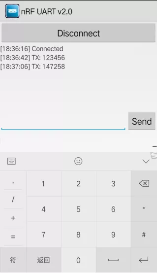
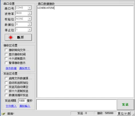
Figure 3 Mobile APP diagram and PC serial port assistant diagram
All reference designs on this site are sourced from major semiconductor manufacturers or collected online for learning and research. The copyright belongs to the semiconductor manufacturer or the original author. If you believe that the reference design of this site infringes upon your relevant rights and interests, please send us a rights notice. As a neutral platform service provider, we will take measures to delete the relevant content in accordance with relevant laws after receiving the relevant notice from the rights holder. Please send relevant notifications to email: bbs_service@eeworld.com.cn.
It is your responsibility to test the circuit yourself and determine its suitability for you. EEWorld will not be liable for direct, indirect, special, incidental, consequential or punitive damages arising from any cause or anything connected to any reference design used.
Supported by EEWorld Datasheet
EEWorld
subscription
account

EEWorld
service
account

Automotive
development
community

Robot
development
community

About Us Customer Service Contact Information Datasheet Sitemap LatestNews


Room 1530, 15th Floor, Building B,
No.18 Zhongguancun Street,
Haidian District,
Beijing, Postal Code: 100190
China
Telephone: 008610 8235 0740
 京公网安备 11010802033920号

 FEVT25P16SG2


