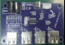
USB HUB-FE1.1S V2.0 explains the reasons before production: 1. Since the USB port used by factory computers is often used to test mouse and keyboard products, over time it will damage the computer’s USB interface, so there is a need to use FE1 .1S to make USB-HUB plan. 2. I often see the works of great people, and I also want to make one myself. 3. The most important thing is that after watching the live broadcast, I also wanted to test my learning results, so I came up with this project. 4. This is version VE1.1S V1.0, which has been open sourced previously. Chip introduction: 1. High performance, low power consumption and high cost performance. 2. Provide 4 USB Ports. 3. Supports 4 LED light indicators during data transmission and provides the function of customizing PID/VID. 4. Built-in 3.3V and 1.8V LDO, simplifying peripheral circuits.
Reasons for making the new version: With the previous version, everything worked fine after being made. However, because the computer USB interface often works in a short-circuit state, the power supply current or voltage of many interfaces cannot reach the 5V and 500mA standards. In this way, if I connect it, the device will not be recognized, or the computer will recognize it but cannot use it. For example, if the barcode gun is connected to the computer, it can recognize the scanned code normally, but the content of the barcode cannot be scanned out. Hence the FE1.1S V2.0 version. Cause analysis: Using a multimeter, we know that the cause is the voltage and current, which is easy to handle. Solution: Now that we know the cause, the solution is to increase the USB voltage and current. Connect an external power supply to the USB_HUB. The one I connected is a 12V power supply. Then use 7805 to step down the voltage to 5V. 7805 can convert the highest voltage of 35V to 5V with a maximum output current of 1A. This will satisfy the need. Notes: 1. It is best not to exceed 12V for the actual measured 7805, otherwise the temperature will be too high and there is a risk of burns if you touch it. 2. USB2.0 devices all work with 5V.500mA current, so a current-limiting resistor must be added to the USB positive electrode. 3. A diode should be added to the line from the positive pole to the USB port of the computer to prevent current from flowing back and burning the computer motherboard.
Note: V2.0 has been boarded, and there is no problem in physical verification. Now it can work normally when connected to 4 USB devices at the same time, which is quite stable.

