This project uses Taoyuanke's STC8H3K64S2 to produce the LCD12864USB voltage and current capacity meter - Lichuang EDA open source hardware platform https://oshwhub.com/taoyuanke/stc8h3k64s2-zhi-zuo-lcd12864usb-dian-ya-dian-liu-rong-liang- The Biao screen uses Lao Wang's 2.5 yuan POS machine disassembly screen with 12864 screen small host 150mah battery screen with information and shell DIY research price - Taobao https://item.taobao.com/item.htm?spm=a1z10 .3-c.w4002-13969304973.28.5dae213221PcKt&id=673458651955
screen uses this
sampling resistor. You can also use 2 milliohms
and add MICROUSB and type c socket.


USB table firmware 1.0.hex
BOM download
PCB_NEW_PCB_2022-09-24.pdf
PCB_NEW_PCB_2022-09-24.json
NEW_PCB_2022-09-24.pcbdoc
Gerber_NEW_PCB.zip
Schematic_STC8H3K64S2 makes LCD12864USB voltage and current capacity table_2022-09-24.pdf
SCH_STC8H3K64S2 makes LCD12864USB voltage and current capacity meter_2022-09-24.json
TSSOP20-1.4-inch screen USB voltage and current capacity table_2022-09-24.schdoc
61281
【CW32】CW32F030 gimbal motor 6.1
Introduction: CW32 gimbal motor FOC driver
CW32F030 PTZ motor driver: Sampling CW32F030 as the main control, TLE5012 encoder sampling SPI connection. For current sampling, low-end sampling is used, two-phase A and B low-end currents are collected, and the sampling op amp samples the INA181N2 op amp that amplifies 50 times. Driver chip, using MP6536 driver chip
VID_1.mp4
BOM download
PCB_PCB_【CW32】CW32F030 PTZ Motor 6.1_2022-09-24.pdf
PCB_PCB_【CW32】CW32F030 gimbal motor 6.1_2022-09-24.json
PCB_[CW32] CW32F030 gimbal motor 6.1_2022-09-24.pcbdoc
Gerber_PCB_[CW32]CW32F030 gimbal motor 6.1.zip
Schematic_[CW32]CW32F030 gimbal motor 6.1_2022-09-24.pdf
SCH_【CW32】CW32F030 gimbal motor 6.1_2022-09-24.json
Sheet_1_2022-09-24.schdoc
61282
STC44ToPDIP40 (to be verified)
Introduction: Convert the 44pin STC microcontroller to PDIP40pin. 2 LEDs provided: Power and P55 IO.
Support USB direct download. It is intended for students who already have experimental boxes and chips.
Connect the 44pin STC microcontroller to PDIP40pin. 2 LEDs provided: Power and P55 IO. Support USB direct download. It is intended for students who already have experimental boxes and chips.
BOM download
PCB_STC8TINY1.0_2022-09-24.pdf
PCB_STC8TINY1.0_2022-09-24.json
STC8TINY1.0_2022-09-24.pcbdoc
Gerber_STC8TINY1.0.zip
Schematic_STC44ToPDIP40(to be verified)_2022-09-24.pdf
SCH_STC44ToPDIP40 (to be verified)_2022-09-24.json
STC8TINY1.0_2022-09-24.schdoc
61283
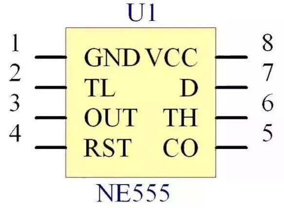
Ultrasonic nebulizer (based on NE555)
Introduction: You can find a lot of relevant principles on Baidu, so I won’t go into details here.
Please see the BOM table for device selection. The piezoelectric ceramics were bought on Taobao with a center frequency of 113KHz.
Frequency adjustment is achieved by adjusting the potentiometer. Be careful not to touch the working piezoelectric ceramics with your hands.
The square wave signal emitted by NE555 has a limited frequency and cannot be used for ultrasonic testing, but it can still be used for atomization. Be careful with the vibrator when using it, as accumulation of ultrasonic energy can burn the skin.
Ultrasonic nebulizer demonstration video.mp4
BOM download
PCB_PCB_Ultrasonic atomizer (based on NE555)_2022-09-24.pdf
PCB_PCB_Ultrasonic atomizer (based on NE555)_2022-09-24.json
PCB_Ultrasonic atomizer (based on NE555)_2022-09-24.pcbdoc
Gerber_PCB_Ultrasonic atomizer (based on NE555)_2022-09-24.zip
Schematic_Ultrasonic nebulizer (based on NE555)_2022-09-24.pdf
SCH_Ultrasonic nebulizer (based on NE555)_2022-09-24.json
Ultrasonic nebulizer (based on NE555)_2022-09-24.schdoc
61284
Laolan soundbar amplifier control panel
Introduction: Laolan Sharp Echo Bar Amplifier Control Panel
Personal version, leads to speaker wiring
3.27 Laolan sound bar control board, unverified
4.2 physical picture, to be updated...
BOM download
PCB_PCB_Laolan power amplifier control board_2022-09-24.pdf
PCB_PCB_Laolan power amplifier control board_2022-09-24.json
PCB_Laolan Amplifier Control Board_2022-09-24.pcbdoc
Gerber_PCB_Laolan amplifier control board.zip
Schematic_Laolan Echo Bar Amplifier Control Board_2022-09-24.pdf
SCH_Laolan Echo Bar Amplifier Control Board_2022-09-24.json
Sheet_1_2022-09-24.schdoc
61285
Guangzong Yaozu
Introduction: Third Prize in the 2022 Guangzhou City Polytechnic School of Electrical Engineering Electrical and Electronic Breathing Lamp Design Competition
Plug in the power, and the 7-Hi logo flickers on and off, indicating that summer is coming and people love ice drinks!

WeChat_20220611131653.mp4
BOM download
PCB_PCB_Guangzong Yaozu_2022-09-24.pdf
PCB_PCB_Guangzong Yaozu_2022-09-24.json
PCB_Guangzong Yaozu_2022-09-24.pcbdoc
Gerber_PCB_Guangzong Yaozu.zip
Schematic_Guangzongyaozu_2022-09-24.pdf
SCH_Guangzong Yaozu_2022-09-24.json
Sheet_1_2022-09-24.schdoc
61286
【Solicitation Order】ESP8266 Weather Clock
Introduction: Based on ESP8266 weather clock, displays local local location, time and local temperature
### Project Introduction
Background: Why do you want to make such a small thing?
I also saw other people doing it. I saw many such open source projects on the Lichuang open source platform and Bilibili, so I simply made such a gadget, the Astronaut Weather Clock.
- - -
### Project function introduction An
introduction and brief introduction to the relevant functions of the project, such as:
* Use 1.54-inch, Zhongjingyuan LCD screen
* PCB and schematic diagram are simply designed by myself. The circuit is very simple.
* Use TYPE-C interface for power supply and program update.
* The 1.54 LCD also has pin header terminals, and the upper and lower PCBs are connected by copper pillars.
* Disclaimer: The program was not written by me. It has been verified that the programs of two open source protocols can successfully light up the display.
* The astronaut with a white background belongs to the UP owner of station B. His open source program is in the attachment.
- -
-Design process:
* [x] Schematic design
* [x] PCB diagram design
* [x] PCB proofing
* [x] Welding test
* [x] Functional test
* [x] Program test
- - -
### The circuit explanation
circuit is relatively simple, no introduction is required
### Software```
C
const char ssid[] = ""; //Just change these two WIFI names
const char pass[] = ""; //WIFI password
```
- - -
### Picture
![image.png]

PCB soldering diagram
![image.png]

![image.png]

- - -
###
- - -
- - -
d66e64fd9cecf78ebb5eef6916f0acc3.mp4
arduino esp8266 astronaut weather clock.zip
BOM download
PCB_PCB_[Solicitation Order] ESP8266 Weather Clock_2022-09-24.pdf
PCB_PCB_[Solicitation Order] ESP8266 Weather Clock_2022-09-24.json
PCB_[Solicitation Order] ESP8266 Weather Clock_2022-09-24.pcbdoc
Gerber_PCB_[Solicitation Order] ESP8266 Weather Clock.zip
Schematic_[Solicitation Order] ESP8266 Weather Clock_2022-09-24.pdf
SCH_[Solicitation Order] ESP8266 Weather Clock_2022-09-24.json
ESP8266 clock weather_2022-09-24.schdoc
61287
electronic


 京公网安备 11010802033920号

 LA1175