If the competition is over, please jump to the open source platform to view the latest version. If the competition is over, the scoring will be locked. At that time, this layout cannot be edited. The most beggar 68+4 mechanical keyboard PRO also has an English version for communication with foreign friends GaiZhongGai-Keyboard-68+4PRO - EasyEDA open source hardware lab (oshwlab.com) Regarding the content, the following description is not all of this keyboard. There is also a sister project "The Most Beggar 17+4+Touch Mechanical Keyboard PRO", and the two are better for consumption together. Coincidentally, the two competitions are now being held at the same time, so the two projects are each invested in different tracks. In order to avoid duplication of content, the focus is different. Preface Many readers who are not in the computer installation circle may not understand the meaning of this beggar among beggars. This word is more used on computer motherboards and graphics cards. It refers to the beggar version of the beggar version, the low configuration of the low configuration, and the shrinkage of the shrinkage, which is homophonic to the former CCTV advertisement. And I am not here for sales promotion, so it is okay to use the most as the project name. The benefits of low configuration are obvious, that is, low cost, and students love it the most. We are all experienced in burning money in electronics, but as a teacher, I hope you will not cut back or even skip meals when you make room for living expenses. You can ask your classmates to share the cost, or use the extra PCBs to assemble and post them on Xianyu to make up for the loss (investment is risky!!!), but remember to comply with the open source agreement. Here is a comparison table of commonly used MCU configurations with the QMK solution. Model STM32F103C8T6GD32F103C8T6ATMEGA32U4-AUCH551G Lichuang No. C8734C77994C44854C108958 Single Price (June 24, 2022) ¥42.58¥14.35¥129.92¥2.69 Package LQFP-48LQFP-48QFP-44SOP-16 I/O Number 37372612.5 (RST pin can only be read, as half) Bits 32-Bit32-Bit8-Bit8-Bit Core ARM® Cortex®-M3ARM® Cortex®-M3AVRC51ROM64kB64kB32kB10kBRAM20kB20kB2.5kB0.75kBEEPROMnone (but can be simulated with FLASH)none (but can be simulated with FLASH)1kB128BThe comparison shows that the configuration is not much different, mainly because there is no ecosystem. When the keyboard was first released, I planned to open source the code, but I felt that it was not popular enough, and I was afraid that someone would take it for profit and delete the original author's information. However, the "chip shortage" caused the price of the above microcontrollers to rise, and my project became more popular. And now there is the spiritual and material support of loyal fans. Please help communicate with the sellers on Xianyu to add the open source label, and reward the author with a fixed amount after the sale. With such support, can the update be diligent? Thank you for your support along the way~1. Project function introduction Based on my old project "The Most Beggar 61+3 Mechanical Keyboard" upgrade. This meets my initial need of having a hub on the keyboard. Since there is no place for the third USB socket, an SD card reader is placed under the space. The layout is modified, the keyboard backlight is changed to RGB, and OpenRGB is connected. Chinese support is also added to the project. Under the poor peripherals of CH551G, a lot of optimizations are made to meet the strict timing requirements of WS2812. Normal state

The most beggar 68-key RGB keyboard program V10 open source.hex
68 keyboard program Ver1.00 (open source version).zip
OpenRGB Chinese version.zip
studio_video_1659892762090 [720p].mp4
VID_20220607_210912~1.mp4
BOM Download
PCB_68+4+HUB+SD Lower Light Position_2022-09-23.pdf
PCB_68+4+HUB+SD lower light position_2022-09-23.json
68+4+HUB+SD downlight position_2022-09-23.pcbdoc
Gerber_68+4+HUB+SD lower light position.zip
PCB_68+4 positioning board_2022-09-23.pdf
PCB_68+4 positioning board_2022-09-23.json
68+4 positioning board_2022-09-23.pcbdoc
Gerber_68+4 positioning board_2022-09-23.zip
PCB_68+4 baseboard (lower lamp position wiring pattern)_2022-09-23.pdf
PCB_68+4 bottom board (lower lamp position wiring pattern)_2022-09-23.json
68+4 baseboard (lower lamp position wiring pattern)_2022-09-23.pcbdoc
Gerber_68+4 baseboard (lower light position wiring pattern)_2022-09-23.zip
PCB_68+4+HUB+SD upper light position_2022-09-23.pdf
PCB_68+4+HUB+SD upper light position_2022-09-23.json
68+4+HUB+SD upper light position_2022-09-23.pcbdoc
Gerber_68+4+HUB+SD upper light position.zip
Schematic_#The 7th Lichuang Electronic Competition#The Most Beggar 68+4 Mechanical Keyboard PRO_2022-09-23.pdf
SCH_#The 7th LiChuang Electronic Competition#The Most Beggar 68+4 Mechanical Keyboard PRO_2022-09-23.json
#The 7th Lichuang Electronic Competition#The Most Beggar 68+4 Mechanical Keyboard PRO_2022-09-23.zip
61685
【Tuya Smart】Guawawa Voice Infrared Butler
Introduction: Gua, here I come! A voice infrared assistant based on the Tuya VWXR2-ES module, supporting a variety of infrared control and learning solutions (no development required)
Hi, here I come! OEM product cloning : I - want
- too ... (You can also use 6 or 8, but you are too lazy to solder . 3. This project has infrared learning, which can learn other remote control devices, so as to achieve remote or automatic control in different directions. 4. This project has network configuration/microphone disable, play/stop buttons, and can expand volume increase and decrease functions. (In order to adapt to the shell, remove the volume increase and decrease) 5. This project has two colors of LED lights to achieve different states of the device. (Red for network configuration/abnormal state, ice blue for listening to voice information) Project pictures: 1. Family bucket 2. PCB front 3. PCB back 4. Assemble the shell 5. Modify the Type-C interface (originally MicroUSB) . 6. Air conditioning control interface 7. PCB design interface notes: 1. How to configure the network for the device: Download the Smart Life app or Tuya Smart app network configuration tutorial: https://blog.csdn.net/sandwich_iot/article/details/121928622?spm=1001.2014.3001.5501 2. Firmware information configuration: 3. Attachment development materials thanks: The PCB frame comes from the user shouji6406 on the site, and the project link is: https://oshwhub.com/shouji6406/tuya_soc_-mo-neng-hong-wai-yao-kong (I slightly modified the aperture inside the frame. If you buy the same kind of shell as me, you can rest assured to make the board. It has been verified)


Asking the Weather.mp4
Control air conditioner.mp4
Adjust volume.mp4
Live broadcast on the 18th PPT.pdf
AI Voice Infrared Remote Control 11-18.pdf
VWXR2-ES Online Voice Module Specification_Document Center_Document Center.pdf
Infrared Voice Assistant Practical Camp-Must-Read Before Joining the Camp (1).pdf
Microphone and speaker selection 11-18.pdf
Power on.mp4
BOM Download
PCB_housing frame_PCB_2022-09-23.pdf
PCB_housing_border_PCB_2022-09-23.json
Shell frame_PCB_2022-09-23.pcbdoc
Gerber_housing frame_PCB_2022-09-23.zip
PCB_GuaWaWa Voice Infrared_PCB_2022-09-23.pdf
PCB_Frog Voice Infrared_PCB_2022-09-23.json
Frog Voice Infrared_PCB_2022-09-23.pcbdoc
Gerber_Frog Voice Infrared_PCB.zip
Schematic_【Tuya Smart】Frog Voice Infrared Butler_2022-09-23.pdf
SCH_【Tuya Smart】Frog Voice Infrared Butler_2022-09-23.json
Croaking Frog Voice Infrared_SCH_2022-09-23.schdoc
61695
【RA】LoRaWAN multi-function node development board based on Renesas RA
Introduction: RALoRaWAN Board is a LoRaWAN node development board based on R7FA2E1A72DFL, which is the RA series Arm® Cortex®-M23 core.
RALoRaWAN_Board V1.0
R7FA2E1A72DFL is an entry-level single-chip microcontroller of the RA series, based on a 48 MHz Arm® Cortex®-M23 core, with up to 64 kB of code flash and 16 kB of SRAM. * 48MHz Arm® Cortex®-M23;
R7FA2E1A72DFL parameters: * Wide operating voltage range of 1.6V - 5.5V; * Enhanced capacitive touch sensing unit (CTSU); * Independent SPI interface/I2C multi-master interface; * 12-bit ADC, LPACMP, temperature sensor; * 32-bit general-purpose PWM timer, 16-bit general-purpose PWM timer, low-power asynchronous general-purpose timer;
Engineering features:
1. Still uses the mainstream interface Type-c.
2. The serial port uses the CH340N chip and communication indicator light.
3. Onboard AHT21 temperature and humidity sensor.
4. One reset button, one BOOT mode selection, and two user-defined buttons.
5. Three custom LEDs on board.
6. Buzzer on board.
7. RA-08 LoRaWAN module on board.
8. OLED screen with IIC protocol reserved.
9. One adjustable resistor on board for ADC learning.
10. SWD test is introduced for external simulation.
11. Power indicator light, hehe.
The PCB adopts the Aruino appearance, but it is not compatible with other Arduino expansion boards! !
Project pictures:

Project display:
The code part does not meet the requirements. . . . . . . . . . .
BOM Download
PCB_PCB_【RA】LoRaWAN multi-function node development board based on Renesas RA_2022-09-23.pdf
PCB_PCB_【RA】LoRaWAN multi-function node development board based on Renesas RA_2022-09-23.json
PCB_【RA】LoRaWAN multi-function node development board based on Renesas RA_2022-09-23.pcbdoc
Gerber_PCB_【RA】LoRaWAN multi-function node development board based on Renesas RA.zip
Schematic_【RA】LoRaWAN multi-function node development board based on Renesas RA_2022-09-23.pdf
SCH_【RA】LoRaWAN multi-function node development board based on Renesas RA_2022-09-23.json
SCH_【RA】LoRaWAN multi-function node development board based on Renesas RA_2022-09-23.schdoc
61696
Brushless DC motor (based on CW32)
Introduction: DC brushless motor learning and development, Wuhan Xinyuan Semiconductor & Lichuang EDA joint training camp
Top board: bring out all the pins of the chip for easy debugging.
Main control board: USB to serial port, Bluetooth, infrared remote control, buzzer, oled screen, JTAG or SWD burning, potentiometer speed control, three buttons, two LED lights. Driver board: DC sensed brushless motor driver, DC senseless brushless motor driver (you can select the endpoint voltage or back electromotive force (virtual midpoint) through the jumper cap), FOC motor driver (selected through the jumper cap), can measure the three-phase current of the motor or only the total current (you can select it through the jumper cap), bus voltage acquisition, temperature measurement.
CW32F030CBT6 motor main control board hardware configuration.xlsx
SCH_CW32F030CBT6 Motor Driver Board V1.0.0_2022-06-16_00.jpg
SCH_CW32F030CBT6 Motor Main Control Board_2022-06-16_00.jpg
CW32F030CBT6 Motor Driver Board.pdf
CW32F030CBT6 Top Plate.pdf
CW32F030CBT6 Motor Main Control Board.pdf
Actual picture.jpg
VID20220623164417.mp4
61717
#The7thLiChuangElectricityContest#USB power meter
Introduction: This USB ammeter is made based on the training camp course. It can check the current/voltage when the USB is working. The original circuit has been partially modified and does not support fast charging.
The USB ammeter made according to the training camp course can check the current/voltage when the USB is working. The original circuit has been partially modified and does not support fast charging.
Referring to the training camp circuit diagram, the circuit was partially modified, USB data connection and two LED lights were added, and the PCB diagram was drawn and printed.


It is a bit uncomfortable to switch from the standard version to the professional version. The main problem is that the local and network are not synchronized.
1. Draw the board, the board of LiChuang, you can use it with confidence.

2. Buy national chips, the mall will reduce 50 for 100. Buy 20P directly for future study. Use the coupons of the training camp to buy some resistors, capacitors, etc.


4. After calibrating the voltage and current, install the shell and use it.

ProProject_#The 7th LiChuang Electric Competition#USB Power Meter.zip
61721
IP6805U QI charging board
Introduction: A solution verification board based on the IP6805U highly integrated QI wireless charging SOC, with internal integrated power MOS, supporting QI WPC V1.2.4 protocol, supporting FOD, and maximum 5W wireless charging.
#Solution verification board based on Injoinic IP6805U wireless charging SOC
##Main features:
*Maximum 5W output power
*Compatible with WPC V1.2.4 protocol
*Support foreign object detection (FOD)
*Internally integrated power MOS
*Integrated voltage/current demodulation
*Minimalist peripheral circuit
[IP6805U Technical Manual](http://www.injoinic.com/wwwroot/uploads/files/20200214/61c3f62b65d561368400a2d0cc2b3a3c.pdf)
##Foreign object detection (FOD) function test: see engineering attachment
###Others: (Basically nonsense, just scroll down if you are too lazy to read it)
About temperature:
I originally wanted to test the temperature of the 2.5W receiving end (CP2021 (Nanjing Coolpo Micro)) after working for 30 minutes. I thought the internal integrated power MOS might generate a lot of heat (I originally planned to stick a heat sink on the back). As a result, in the winter in the north, the power of less than 2.5W can't heat up at all, and the thermocouple of the multimeter on hand is also broken, so I just give up (manual funny).
Resonant capacitor & coil:
I use NPO capacitors (4 100nf in parallel, a total of 400nf), which is actually quite expensive (7 yuan for 10 pieces). It is mainly for good looks. If you don't mind the appearance, you can use CCB (see the technical manual for details).
The coil uses the A11 coil of the QI standard (a lot of Taobao).
Interface:
The main reason for using the micro interface is that I haven't entered the typec era (I have the castrated version of Honor 8), and the C port in my hand is 16PIN, and I don't want to waste it. If you don't want to buy a micro, you can directly remove a USB cable. There is a pad for the power cord on the PCB.
Pad:
The pad of the coil seems a bit small, but it's not unusable (funny). If you think it's small, remember to change it before placing an order.
Emmmm, no more nonsense. This is my first open source, I don't have much experience, thank you for reading.
I wish you success once and never solder!
VID_20220115_155532_Trim.mp4
BOM Download
PCB_IP6805UQI wireless charging board_2022-09-23.pdf
PCB_IP6805UQI wireless charging board_2022-09-23.json
IP6805UQI wireless charging board_2022-09-23.pcbdoc
Gerber_IP6805UQI Wireless Charging Board.zip
Schematic_IP6805U QI charging board_2022-09-23.pdf
SCH_IP6805U QI charging board_2022-09-23.json
IP6805U_2022-09-23.schdoc
61754
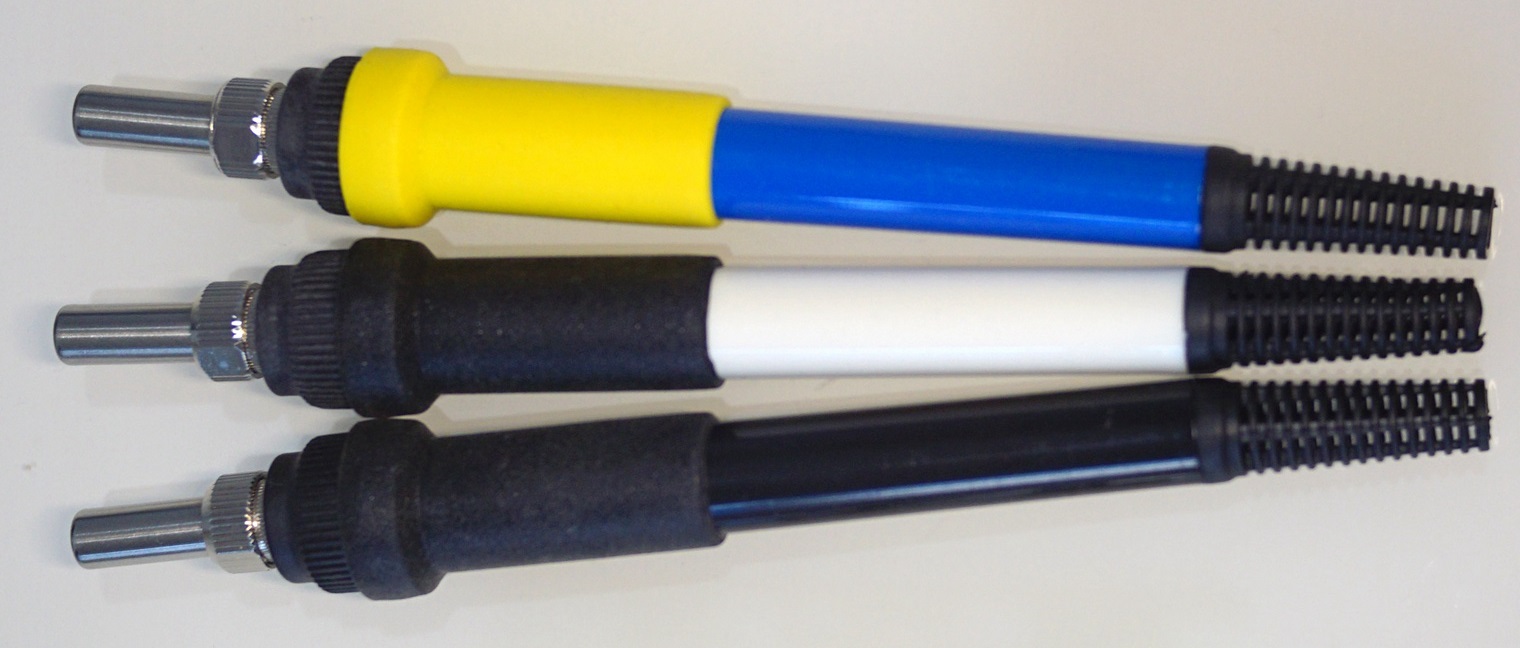
T12, the handle is integrated with the control panel, and it is changed to the size of the board
Introduction: Porter https://oshwhub.com/zanfi1010/shuo-ma-zhi-jia616_-you-hua_copy_copy_copy_copy_copy
Porter https://oshwhub.com/zanfi1010/shuo-ma-zhi-jia616_-you-hua_copy_copy_copy_copy_copy_copyChange to size
1. Source: This circuit is modified based on the 616 circuit circulated on the Internet. As for the origin of the 616 circuit, I have not fully verified it (in fact, why it is called 616, I have not found accurate information). According to online information, it is a great god of Digital Home. This project is also inspired by relevant online resources. For the P-Mos version and the N-Mos version, I prefer the P-Mos version, which has higher reliability. I am very grateful to the predecessors for laying the foundation.
2. Advantages: The circuit is simple and reliable, heats up quickly, and can effectively maintain a constant temperature. Analog circuits are not restricted by the soaring prices of chips. The material cost is extremely low, and it is not painful to toss around at will.
2. Applicable handles:
3. Improvement points:
(1) Improved the reference voltage circuit of LM358 pin 2: Since R4 is much larger than R8, R11 and R12, and R7 is much larger than R8, the reference voltage of LM358 pin 2 caused by R4 and R7 can be ignored, and can be calculated by a simple resistor voltage divider formula, and R7 can be ignored when calculating.
(2) Added reed switch sleep function. When in sleep mode, the voltage of LM358 pin 2 depends on the voltage divider of R12. Therefore, no matter what temperature the potentiometer is adjusted to, the sleep temperature is always the same. The soldering iron rack needs to add a magnet to use the sleep function.
4. Some notes:
(1) The control board cannot be made shorter, and its length is greater than 100mm;
(2) A thermometer is required. Different manufacturers produce different T12 soldering iron tips and thermocouples. Different LM358s also have different degrees of influence on temperature. The resistance values of R8, R11 and R12 determine the maximum temperature, minimum temperature and sleep temperature respectively. The resistance values shown in the figure are for reference only, or in other words, they need to be adjusted appropriately after the board is tested. After testing, the original 616 circuit also has this situation.
This circuit can also be changed into a separate control board, and some or all of R8, R11 and R12 can be replaced with adjustable resistors to adjust the maximum temperature, minimum temperature and sleep temperature separately.
(3) I did not spend the effort to find a more practical potentiometer R7, which is not convenient for adjusting the temperature in actual use. I adjusted it to 320℃ and used it at a constant temperature.
(4) In order to reduce the PCB area, the PCB is not silk-screened, and the artifact IBOM is uploaded in the attachment.
(5) The component model and package directly refer to the BOM of LiChuang EDA; but I did not purchase the components in LiChuang Mall, so the supplier number may not be accurate.
V. References:
(1) Working principle of the control circuit of Baicai Baiguang T12, how does the two-wire heating core achieve heating and temperature measurement?
(2) Analysis of the working principle of T12 soldering iron, see how T12 performs temperature control
(3) Analysis of the driving circuit of Baicai Baiguang T12 (I have doubts about the base state of the N-Mos version of the transistor, it is recommended for reference only)
(4) Add a sleep function to the hollow scaffolding T12
(5) Some other information can be found in the attachment
BOM Download
PCB_PCB1+1 copy_2022-09-23.pdf
PCB_PCB1+1 copy_2022-09-23.json
PCB1+1 copy_2022-09-23.pcbdoc
Gerber_PCB1+1 copy.zip
PCB_PCB1+1_2022-09-23.pdf
PCB_PCB1+1_2022-09-23.json
PCB1+1_2022-09-23.pcbdoc
Gerber_PCB1+1.zip
PCB_PCB_2022-09-23.pdf
PCB_PCB_2022-09-23.json
PCB_2022-09-23.pcbdoc
Gerber_PCB.zip
PCB_Reed switch+vibration switch T12 bracket_2022-09-23.pdf
PCB_Reed switch + vibration switch T12 bracket_2022-09-23.json
Reed switch + vibration switch T12 bracket_2022-09-23.pcbdoc
Gerber_Reed switch + vibration switch T12 bracket_2022-09-23.zip
Schematic_T12, handle integrated control board, changed to board size_2022-09-23.pdf
SCH_T12, integrated control panel in the handle, changed to the board size_2022-09-23.json
T12, integrated control panel in the handle, changed to the size of the board_2022-09-23.zip
61764
STC8H3K64S2 makes 12864LCD dual-channel voltage and current capacity meter
Introduction: Copy the homework of the great god and share the process https://www.mydigit.cn/thread-298246-4-1.html
Low-cost coulomb meter, except for the screen 9.9 free shipping, everything else is very cheap
Copy the homework of the great god and share the process
https://www.mydigit.cn/thread-298246-4-1.html
https://oshwhub.com/13977300488/stc8h3k-tssop20-dian-ya-dian-liu-biao_copy_copy_copy
First post the finished product picture, the interface is complete, usb typc-c xt30


originally used the disassembled card machine screen, replaced with tb 9.9 free shipping st7567 LCD128*64, this screen has many twists and turns. It turns out that 3.3v can't light up but only the backlight. It must be greater than 4.2v to be normal. I originally wanted to power it with a lithium battery, and the ldo couldn't work properly under 5v, so I had to change to an external power supply.
https://item.taobao.com/item.htm?spm=a1z0d.6639537.1997196601.235.687274840CoKtg&id=588631508167


4-19 Now I directly fly the wires and add a physical toggle switch to solve the problem of low voltage and cannot start. XL1059 adjusts the voltage to 4.2v, and 5v input is finally possible.

I have tried 3 meters, 2 hardware ina266, one esp32 pico d4, and one stm32. STC8H is a pure 12-bit ADC microcontroller. The accuracy
of STC8H microcontroller is ok. It turns out that the previous STC8 The program of the 15 series is different. This screen is too big. I want to port it to 0.96tft or 0.96oled. I spent a day to light up a 0.96 oled, but the tft can't light up and flickers. I don't have the ability to do it. I won't bother anymore.


STC8H3K64S2_TSSSOP20 dual 12864 voltage and current meter - copy.rar
WeChat_20220419142555.mp4
BOM Download
PCB_PCB_STC8H3K64S2 makes 12864LCD dual-channel voltage and current capacity table copy_1.8_2022-09-23.pdf
PCB_PCB_STC8H3K64S2 makes 12864LCD dual-channel voltage and current capacity table copy_1.8_2022-09-23.json
PCB_STC8H3K64S2 makes 12864LCD dual-channel voltage and current capacity table copy_1.8_2022-09-23.pcbdoc
Gerber_PCB_STC8H3K64S2 makes 12864LCD dual-channel voltage and current capacity table copy_1.8.zip
Schematic_STC8H3K64S2 makes 12864LCD dual-channel voltage and current capacity table_2022-09-23.pdf
SCH_STC8H3K64S2 makes 12864LCD dual-channel voltage and current capacity table_2022-09-23.json
TSSOP201.4 inch LCD dual voltage and current capacity meter_2022-09-23.schdoc
61765
【CW32】CW32 brushless motor
Introduction: CW32 brushless motor driver
Understand and learn the use of CW32 and the drive of brushless DC motors. This project includes a brushless DC motor driver board and a CW32F030C8T6 driver board. Physical objects and verification have been completed.
202206232250.mp4
BOM Download
PCB_PCB_driver board_2022-09-23.pdf
PCB_PCB_driver board_2022-09-23.json
PCB_driver board_2022-09-23.pcbdoc
Gerber_PCB_driver board.zip
PCB_PCB_CW32_DRV_2022-09-23.pdf
PCB_PCB_CW32_DRV_2022-09-23.json
PCB_CW32_DRV_2022-09-23.pcbdoc
Gerber_PCB_CW32_DRV.zip
Schematic_【CW32】CW32 brushless motor_2022-09-23.pdf
SCH_【CW32】CW32 brushless motor_2022-09-23.json
【CW32】CW32 brushless motor_2022-09-23.zip
61785
electronic


 京公网安备 11010802033920号

 7404
7404


