Updated 2023.12.06: Verified that a memory card can directly install a bootable Synology 7.21 clone without needing to obtain the PID or VID.
I bought an engineering motherboard for installing the clone, which meant some expansion ports on the motherboard were unusable, which was quite wasteful. Plus, I saw some people selling clone bootable Synology disks on Xianyu (a second-hand marketplace), which I looked at and realized were basically "card readers" with the corresponding clone boot image flashed inside.
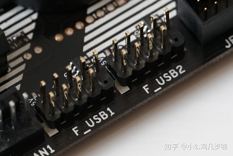
So I did some research and decided to use the unused 9-pin USB port on the motherboard as an expansion port, bringing out a TF card slot and a USB 2.0 female connector
. The idea was to use the memory card as a boot image to install the clone.
I tested both ports and they were recognized normally, but I haven't verified the boot image step yet. Theoretically, it should work. If not, it will probably still require the VID and PID values, which I can then obtain by designing an adapter board.
Of course, this board can also be modified for other interesting or fun functions.
One important point to note is that this board uses a 2.54mm pin pitch for its header females. Some motherboards may use different pin pitches. I also drew a separate board with a 2.0mm pin pitch.
Although my schematic uses SMAJ5.0A and SS14, I found that I have SMF5.0A and DSS14 on hand, which can be directly replaced without any problems.
Also, make sure your motherboard's pin definitions are 5V, D-, D+, and GND.
I've marked these on the board; pay attention to the mounting orientation.
This electronic keyboard, based on the CH32V003A4M6 and BS816A-1 capacitive touch chips, can play 8 notes
. It is easy to assemble, uses a large package, is easy to solder, and is suitable for hardware beginners.
The touch buttons are capacitively capacitively oriented, eliminating the need for soldered components.
Two BS816A-1 chips provide touch level feedback, along with LEDs for user feedback.
Combined with a small speaker and a CH32V003A4M6, it functions as an electronic keyboard.
The program's pitch might be slightly off, but overall it's usable.

electronicOrgan.hex
PDF_CH32-based Touchscreen Electronic Keyboard 2023-v3.0.zip
Altium_CH32-based Touch Keyboard 2023-v3.0.zip
PADS_CH32-based Touch Keyboard 2023-v3.0.zip
BOM_CH32-based Touchscreen Electronic Keyboard 2023-v3.0.xlsx
96865
2.5-inch hard drive enclosure
A 2.5-inch hard drive enclosure based on JMS578 and supporting USB 3.0.
1. The schematic diagram is referenced from: USB to SATA Hard Drive Enclosure Based on JMS578 [Verified] - JLCPCB EDA Open Source Hardware Platform (oshwhub.com).
Based on this, the USB interface has been changed to a USB-A female connector, and the DC interface has been removed.
2. Stack-up structure: JLC0216. To ensure the same size as a 2.5-inch hard drive, the PCB size slightly exceeds the 10*10mm limit for free board making. Those who want free board making can reduce the size and redo the copper pour.
3. Except for the main chip JMS578 and Flash PM25LV512, all components in the BOM are selected from the optimal part numbers of their corresponding specifications on the LCPCB website (based on the Guangdong warehouse). One-click ordering is supported.
If you choose to purchase these yourself, please ensure you select the SMT model on the SATA female connector.
4. Flash firmware is detailed in the attached bin file and can be programmed using J-Link.
5. The underlying numerical diagram is shown below. For detailed numerical diagrams and reference numerals, please refer to the attached PDF file. After inserting
the actual product image

into the computer, the Device Manager can recognize the device as shown in the image below:
Actual transfer speed under USB 3.0 connection:

Finally, a note: As you can see from the last image, currently, with color silkscreen printing, if the solder mask layer is opened, the resulting board will most likely have the solder mask peeling off; also, judging from the link to this project, the author is a complete idiot who participated in an activity, designed a four-layer board, only to discover during prototyping that color silkscreen printing doesn't support four-layer boards and that four-layer boards cannot be converted to two layers, ultimately hastily changing the project title (;´д`)ゞ
2.5-inch hard drive enclosure numerical diagram and reference number diagram.pdf
JMS578.bin
MS578 Datasheet V1.01.pdf
2.5-inch SSD.png
PDF_2.5-inch Hard Drive Enclosure.zip
Altium 2.5-inch Hard Drive Enclosure.zip
PADS 2.5-inch Hard Drive Enclosure.zip
BOM_2.5-inch hard drive enclosure.xlsx
96866
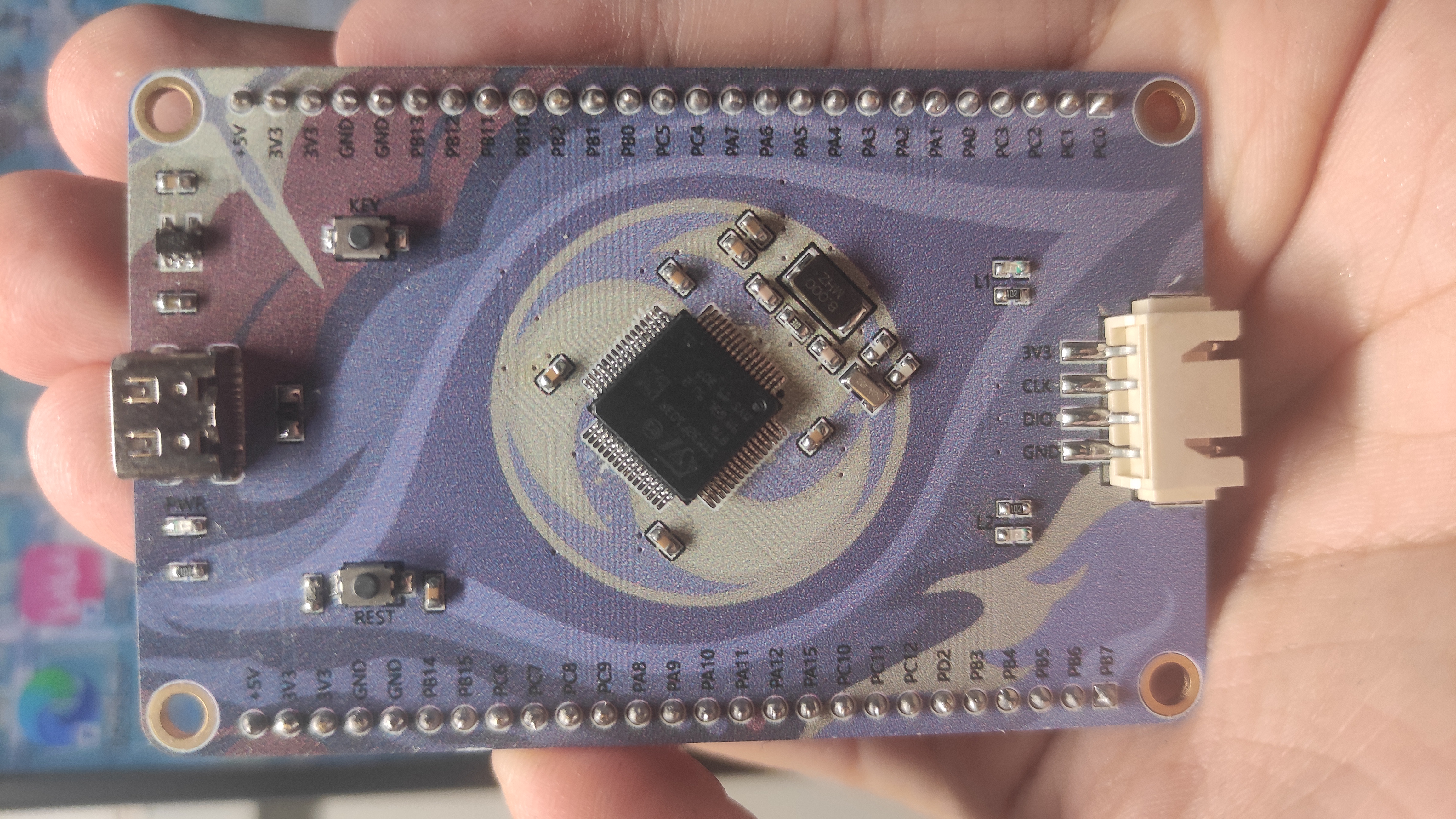
CxT6 core board base plate
Baseboard suitable for various CxT6 core boards
Those who have studied microcontrollers almost universally own numerous STM32F103C6T6 core boards. Using core boards for learning offers undeniable flexibility. However, direct connection with DuPont wires can lead to various problems, such as insufficient current, incorrect wiring, and loose connections. This board is designed to utilize existing components and thoroughly test various microcontroller peripherals. Because the market is flooded with various core boards of varying quality, this design uses the most affordable pinout of the STM32F103C6T6 as the standard. It is also compatible with other microcontroller boards from HoloMatic.
DAPlink.hex
stm32f103xb_stm32f103rb_if.hex
PDF_CxT6 Core Board Baseboard.zip
Altium_CxT6 core board baseplate.zip
PADS_CxT6 core board baseplate.zip
BOM_CxT6 Core Board Baseboard.xlsx
96869
USB 3.0 hub (Type-C, reversible plug)
This USB 3.0 hub, based on the VL813, features a one-to-four configuration and uses a Type-C interface, supporting reversible plugging.
I. Design Summary:
This USB 3.0 hub based on VL813 adopts a one-to-four structure. The hub uses a Type-C interface and supports reversible insertion.
II. Design Schematic Diagram

III. PCB Diagram
(Front

and Back) IV
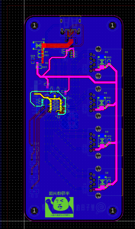
. Physical Display


V. Precautions:
(1) The interface uses Type-C. If you want the interface to support reversible insertion, you need to add a VL160 chip. Without adding a VL160, only one side of the interface can recognize USB 3.0, and the other side can only recognize 2.0.
(2) VL813 can be considered as a replacement for 812. The functions and circuit connections are the same, and 813 is cheaper.
VI. Function Demonstration

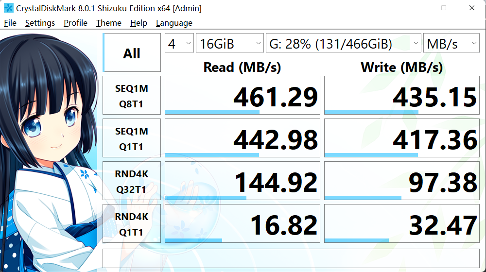
: Speed test can run at full speed of solid-state.
da5a139372bdc96095f2a20571fae3b9.mp4
PDF_USB3.0 Hub (Type-C, Reversible).zip
Altium USB 3.0 Hub (Type-C, reversible plug supported).zip
PADS USB 3.0 Hub (Type-C, reversible plug supported).zip
BOM_USB3.0 Hub (Type-C, Reversible).xlsx
96871
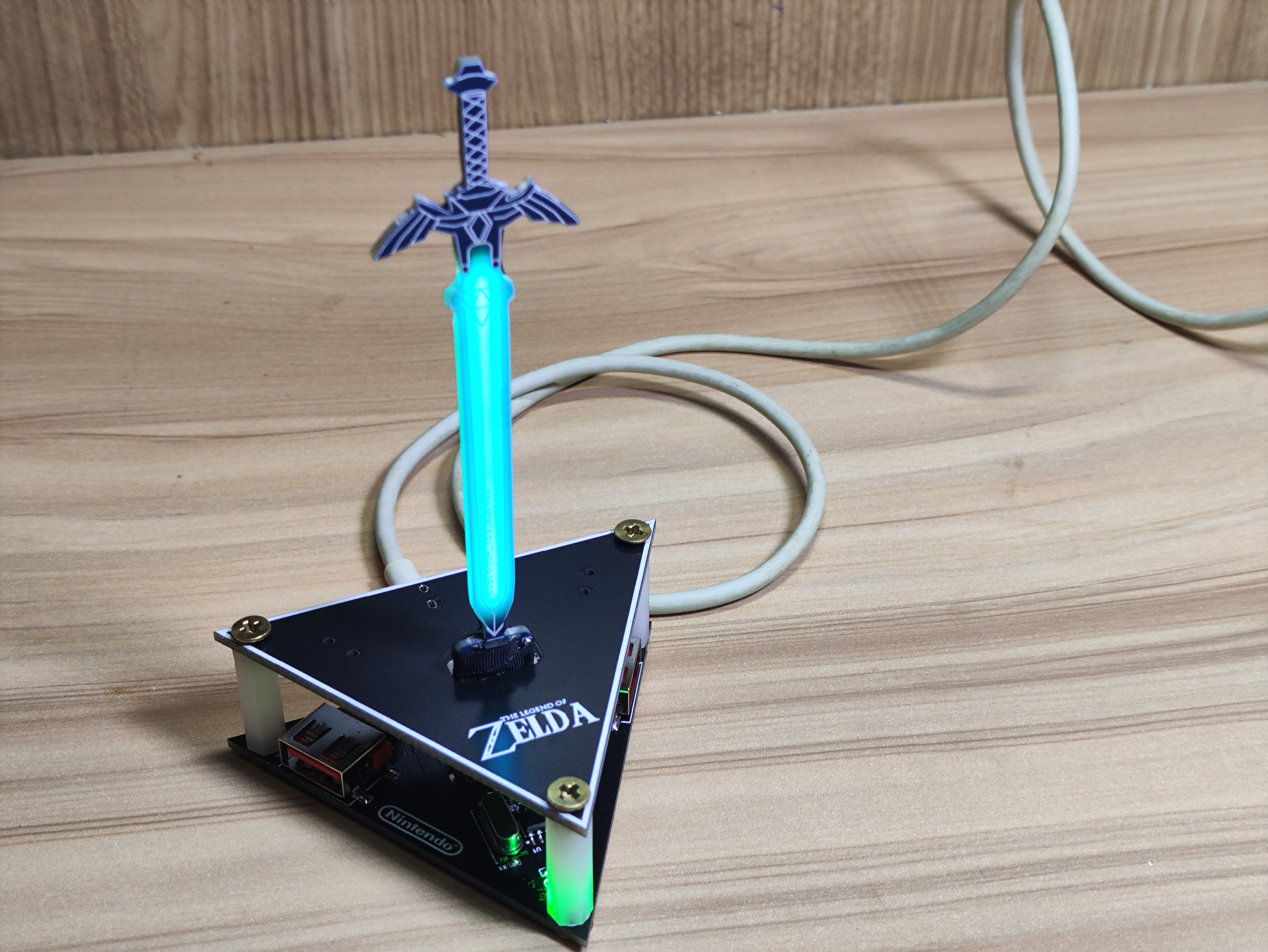
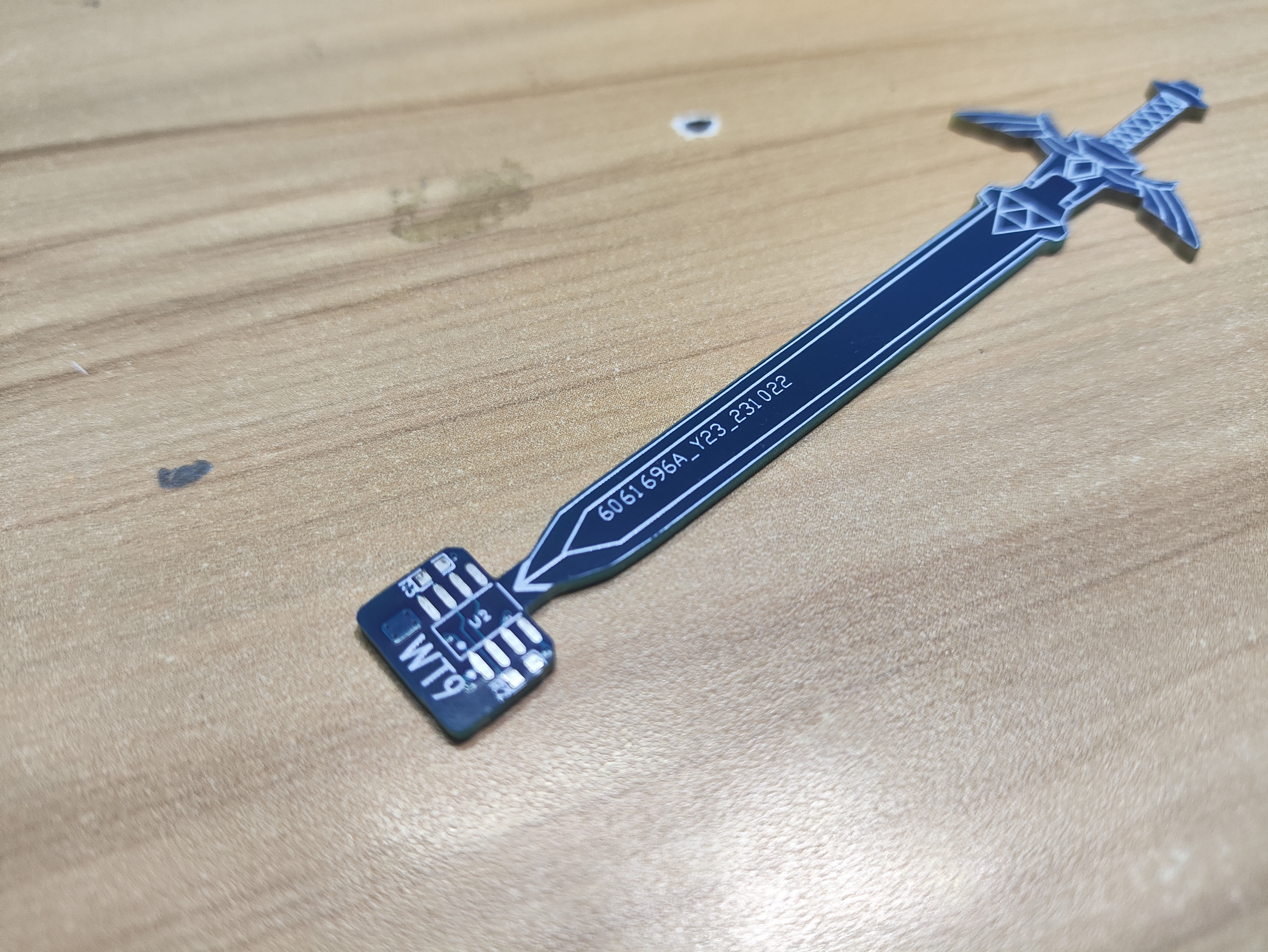
(Editing in progress) NE555 Breathing Light - Master's Sword
NE555 Breathing Light - Master's Sword
This is my first attempt at making something like this, so it's quite rough. I hope everyone can offer their feedback. I was inspired after completing the final stage of the Sword Trial, and this idea suddenly came to me. I made the Master Sword and used a PCB to create a small decorative
base, adding a USB 2.0 hub for increased usability.
-------------------------------------------------------------------------------
The USB hub wiring is not yet standardized, and I cannot guarantee that it will work properly with all USB devices. It will be updated and modified later (please use a 12MHz crystal oscillator).
-------------------------------------------------------------------------------
The sword uses an NE555 as its breathing light. The sword can be plugged into any Type-C device with an output function, and it works normally in all tests. The actual effect is slightly blue; I feel it looks better in photos.
PDF (Editing in progress) NE555 Breathing Light - Master's Sword.zip
Altium_(Editing) NE555 Breathing Light - Master's Sword.zip
PADS_(Editing) NE555 Breathing Light - Master's Sword.zip
BOM (Editing) NE555 Breathing Light - Master's Sword.xlsx
96872
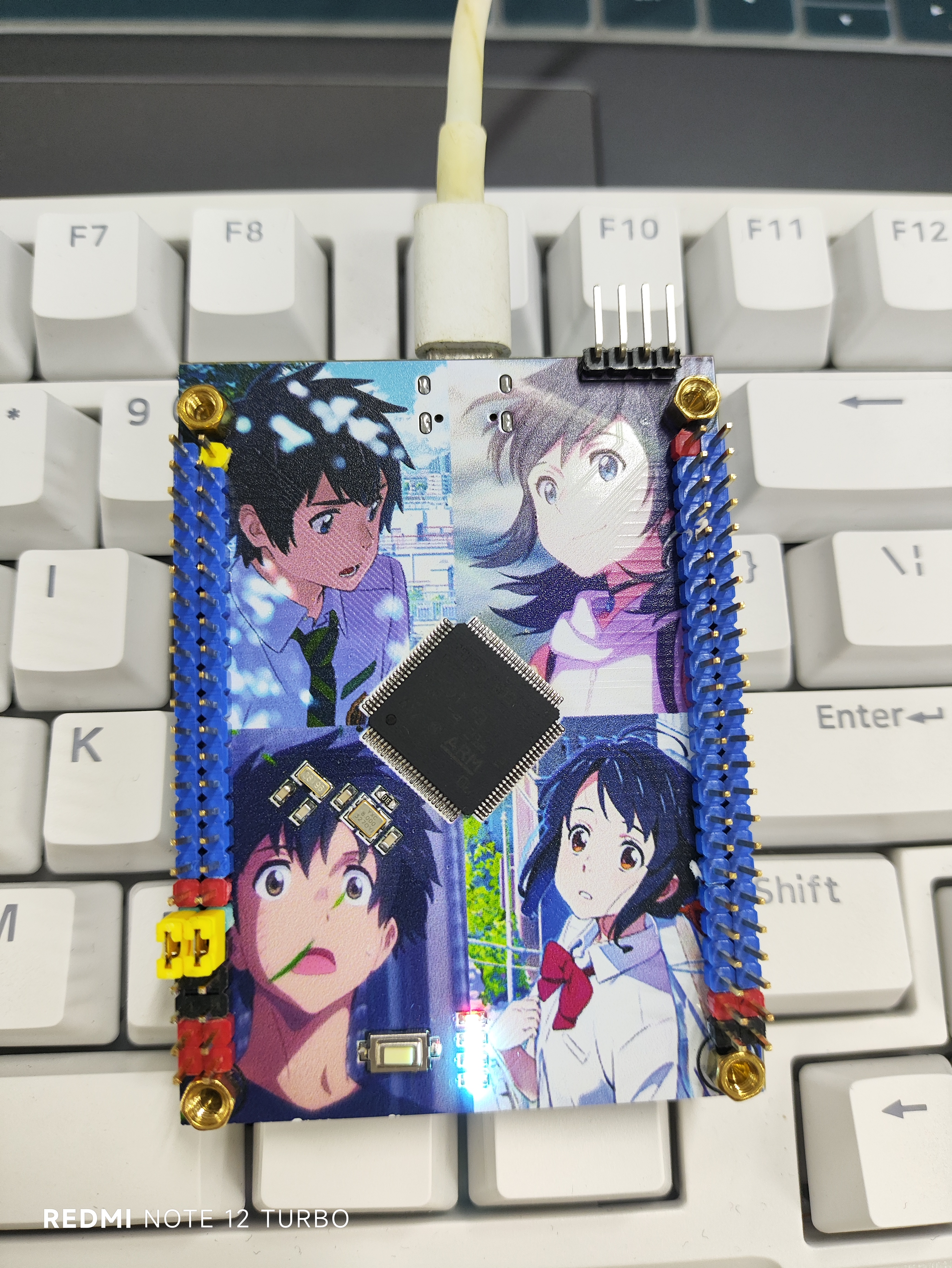
stm32f103vet6 (Weathering With You)
STM32F103VET6 Minimum System Board
All pins on the STM32F103VET6 minimum system board are brought out
to support serial port download.
(Note: The last part, "新海真超丝印
巨巨巨帅," appears to be a nonsensical string of characters and doesn't translate directly.)

PDF_stm32f103vet6 (Weathering With You).zip
Altium_stm32f103vet6 (Weathering With You).zip
PADS_stm32f103vet6 (Weathering With You).zip
BOM_stm32f103vet6 (Weathering With You).xlsx
96873
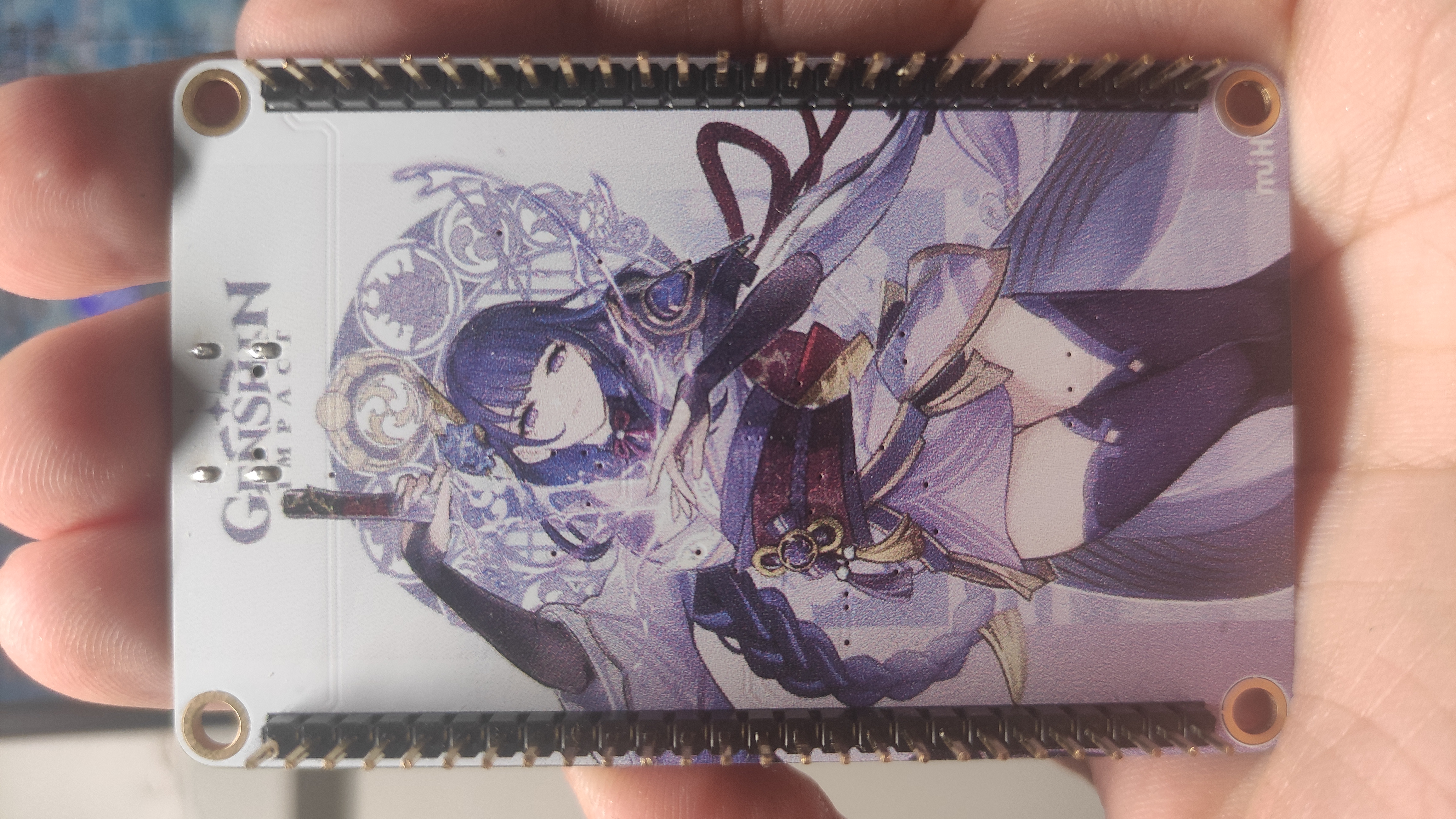
STM32 core board Genshin Impact Raiden General (color silkscreen printing)
STM32 core board Thunder General (color silkscreen printing)
Design Reference: [Color Silkscreen] N32 "Thor" Core Board - JLCPCB EDA Open Source Hardware Platform (oshwhub.com)
PB8, PB9, and PC13 pins are not brought out; the project can be modified if needed.
PDF_STM32 Core Board Genshin Impact Raiden General (Color Silkscreen) .zip
Altium_STM32 core board Genshin Impact Raiden General (color silkscreen printing).zip
PADS_STM32 Core Board Genshin Impact Raiden General (Color Silkscreen Printing).zip
BOM_STM32 Core Board Genshin Impact Raiden General (Color Silkscreen Printing).xlsx
96874
Sword Comes NFC Ruler
Sword Comes NFC Ruler
Sword Comes Color Silk Screen Printing
PDF_Sword Comes NFC Ruler.zip
Altium_Sword Comes to NFC Ruler.zip
PADS_Sword Comes to NFC Ruler.zip
BOM_Sword Comes NFC Ruler.xlsx
96875
3D printer
This project utilizes the STM32F103C8T6 microcontroller to create an affordable 3D printer motherboard, aiming to improve self-developed 3D printers. It seeks to provide users with a new solution for high-performance, high-precision printing. Currently, this solution is a verification version V1.0, and will be gradually improved in later stages.
I chose the STM32F103C8T6 microprocessor as the main control chip to build a 3D printer based on the Corexy architecture. Although this chip is relatively low-end, it can still provide reliable control capabilities for the printer. Currently, I'm using it as a verification version because its GPIO ports and processing speed may be insufficient in certain scenarios. Therefore, I plan to consider using a higher-level STM4-7 series chip in future upgrades to improve system performance and processing speed.
This verification version is an initial exploration of the project, but I don't stop there. If the verification version runs successfully, I will continue to refine this project. The current panel only contains the basic components required for a 3D printer. In the future, I plan to add features such as remote access and Bluetooth connectivity to improve the user experience and expand the printer's functionality.
PDF_3D printer.zip
Altium_3D printer.zip
PADS_3D printer.zip
BOM_3D printer.xlsx
96876
electronic


 京公网安备 11010802033920号

 DDZX9716


