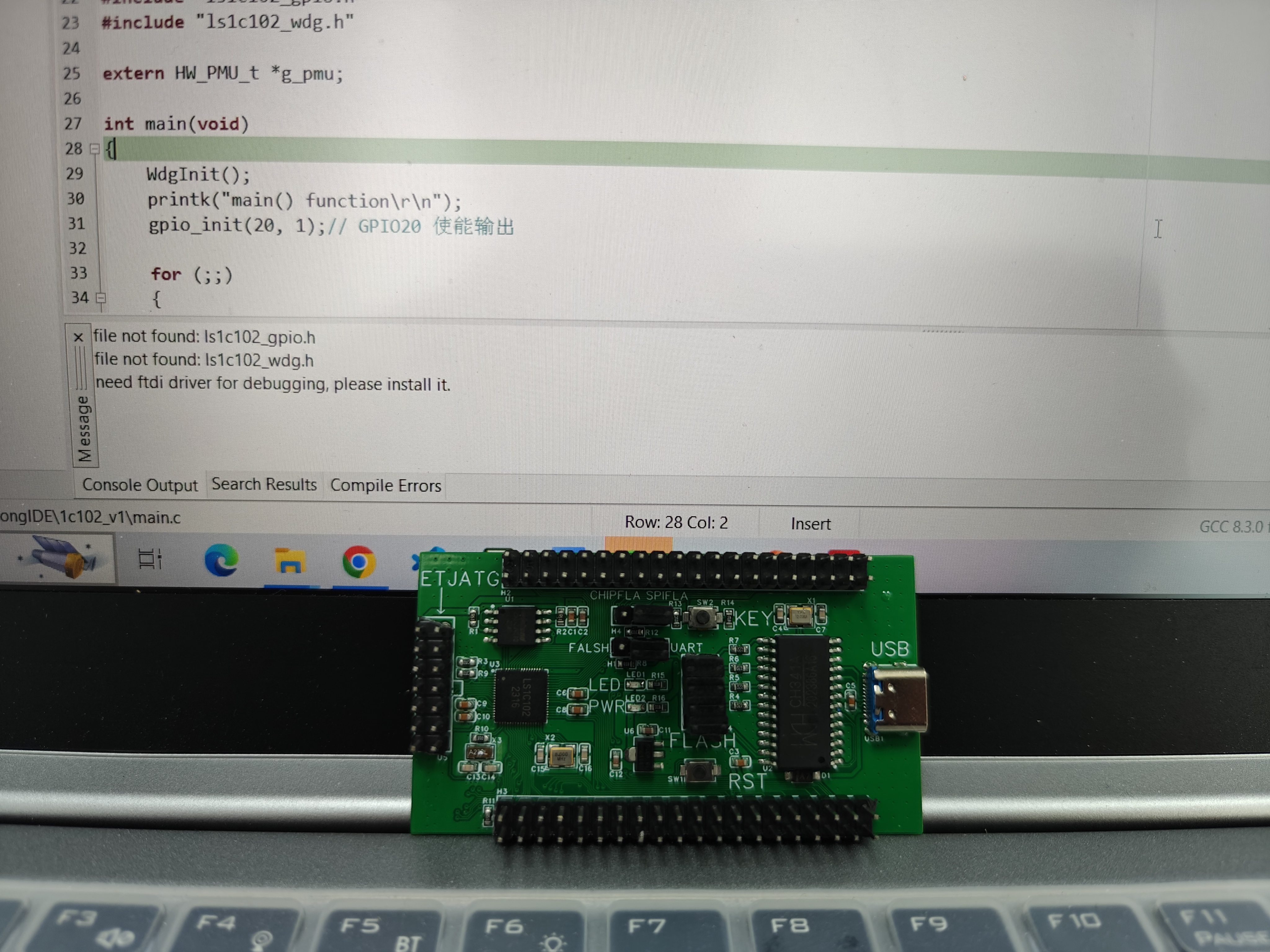
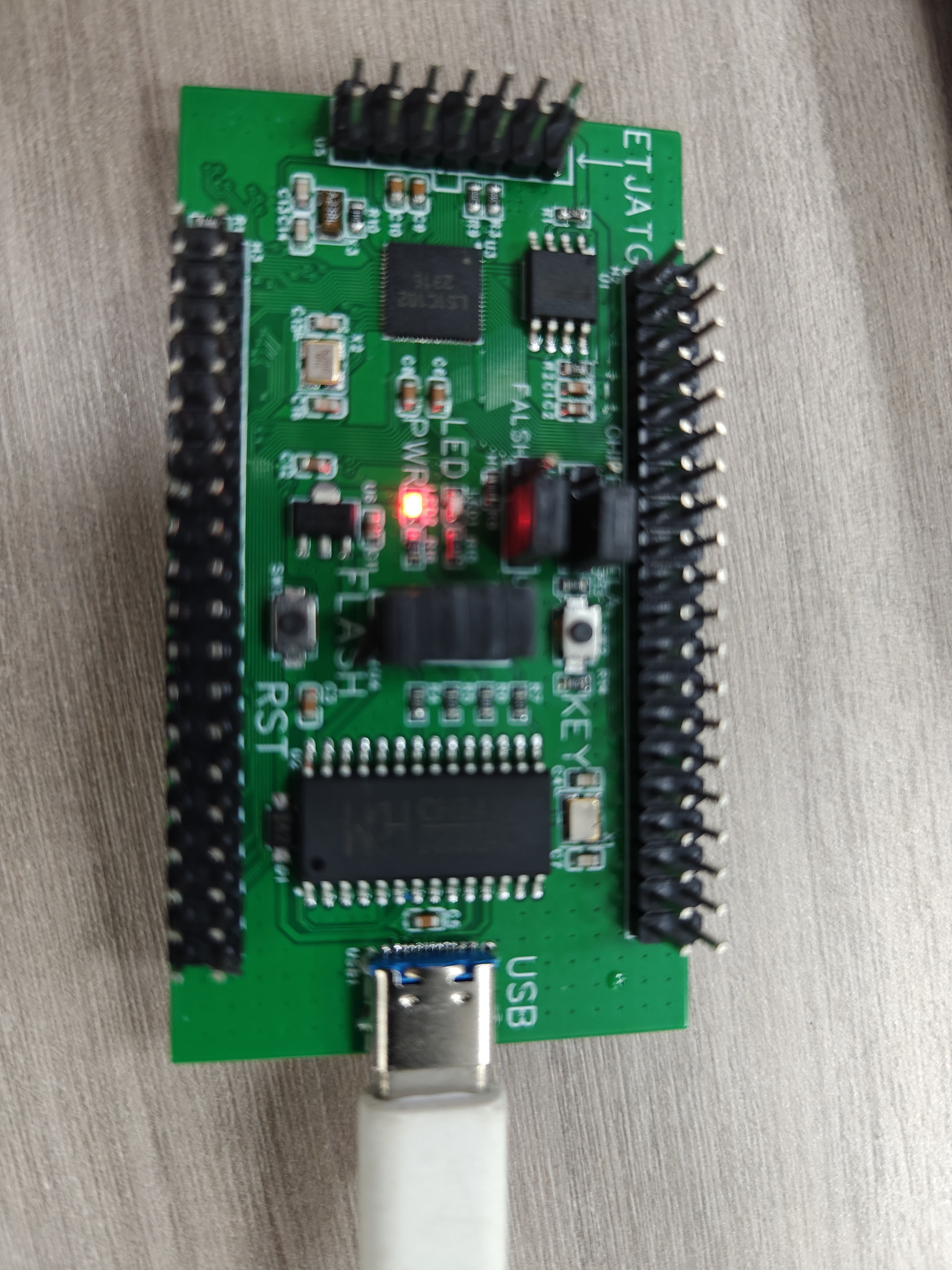
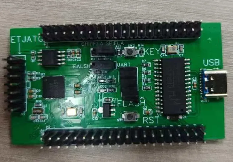
The cost of replicating this development board is approximately 20 RMB. It includes an Lxlink interface and an SPI flash programming port. For detailed instructions, please see the following link: https://pan.baidu.com/s/1fqLIFlJJCwODbbcj5FK11w Extraction code: 2kvy.
There is still room for cost optimization on this development board. For example, the onboard CH341A can be removed and replaced with a CH341 flash programmer, as shown in the image below.

Currently, the board has just been programmed and issues are being investigated.
PDF_Loongson 1C102 Development Board.zip
Altium_Loongson1C102 development board.zip
PADS_Loongson1C102 Development Board.zip
BOM_Loongson 1C102 Development Board.xlsx
92664
DIY MMOS Force Feedback Steering Wheel - V1.3
Currently updated to version V1.3, basic functions have been tested and are working fine. Those with the skills can try soldering it onto a PCB themselves.
Supported features: 1. Supports 16 STM32_PIN buttons. 2. Supports SPI1 expansion of MCP23S17 modules and Logitech G25/G27 shifters. 3. Supports sequential shifting Analog X/Y. 4. Supports USB DFU/UART/SWD programming and download modes. 5. Supports Yifeng AASD/Delta ASDA-AB/Riding DCS servo motor drivers. 6. Supports three pedals + handbrake four-channel analog signal VAA=3.3V. 7. Supports PWM+DIR and H-bridge output mode switching, selectable via jumper caps. 8. PWM analog chip uses GP8101, and optocouplers use high-speed optocouplers HCPL2630SD and PC817D SMD. Items 2 and 3 have not yet been tested, but theoretically they should work. Version V1.3 is the version with basic functions tested and working correctly; everything is OK except for items 2 and 3 which have not been tested.
1718091575486.jpg
ace32d31a7ab9a1fea641673bc688df.jpg
9c957155d90469eb1bfc70c93339a905.mp4
PDF_MMOS Force Feedback Steering Wheel DIY-V1.3.zip
Altium_MMOS Force Feedback Steering Wheel DIY-V1.3.zip
PADS_MMOS Force Feedback Steering Wheel DIY-V1.3.zip
BOM_MMOS Force Feedback Steering Wheel DIY-V1.3.xlsx
92666
Voltage and current meters based on the CW32F030C8T6 development board of the EarthStar platform
LCSC GeoStar CW32 Digital Voltage and Current Meter Expansion Board
I. Design Background
An ADC (Analog-to-Digital Converter) is an indispensable key component in electronic systems. It converts continuous analog signals into digital signals, enabling digital processing and analysis. ADCs play a crucial role in signal conversion, measurement and data acquisition, control system input, and communication and signal processing. Their widespread application promotes the intelligent and precise control of electronic equipment across various industries, and is one of the key factors driving modern technological progress. Digital voltmeters and ammeters combine ADC technology with circuit measurement principles, accurately converting analog voltage and current signals into digital displays for easy reading and analysis by electronic engineers. This device not only improves the accuracy and efficiency of circuit measurements but also helps engineers better understand circuit behavior, serving as a powerful assistant in electronic design and troubleshooting, and playing a vital supporting role in the work of electronic engineers. In product applications, digital voltmeters ensure the accuracy and safety of circuit design, while also providing strong support for product quality control and subsequent maintenance. Learning to design and build a digital voltmeter and ammeter
using a benchtop digital multimeter (Agilent 34401A)
is highly beneficial for improving one's professional skills. This digital voltmeter and ammeter project covers multiple aspects, including microcontroller circuit design and implementation, signal acquisition and processing circuit design, user interface development and optimization, and product appearance design. It integrates knowledge from multiple fields such as electronics, microcontroller programming, circuit design, and industrial design. Considering the learning pace and knowledge absorption capacity of beginners, we have specially launched this introductory-level digital voltmeter and ammeter project, which is very suitable for beginners in electronics and those who want to learn more about microcontroller applications. This project has the following highlights:
it adopts a core board plus expansion board design concept and uses plug-in components, making learning simpler and exploration more in-depth;
the core board uses the domestic Wuhan Xinyuan Semiconductor CW32 as the main controller, while also being compatible with other similar development boards; however, the CW32 has advantages.
The project is highly comprehensive and practical, and after completion, it can be used as a desktop instrument;
the project has abundant learning materials, including circuit design tutorials, PCB design, code programming learning, and training for engineers' debugging skills.
II. Hardware Design
1. Power Supply Circuit
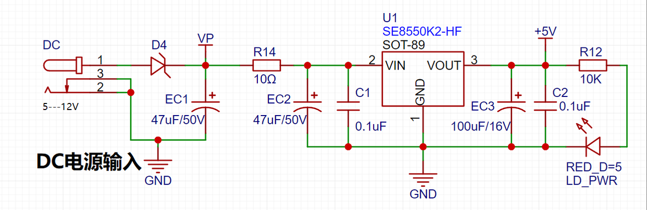
LDO (Low Dropout Linear Regulator) Selection This project uses an LDO as the power supply. Considering that most voltmeter products are used in industrial scenarios with 24V or 36V power supplies, the SE8550K2 with a maximum input voltage of up to 40V was selected as the power supply. The main reason for not using a DC-DC step-down circuit to handle the large voltage drop is to avoid introducing DC-DC ripple interference during the design process, and the secondary reason is to reduce project costs.
2. MCU Selection Analysis
To reduce the learning cost for everyone, this project uses the LCSC CW32F030C8Tx development board (core board) as the main controller, but this does not mean that we will talk less about this section. From the perspective of training engineers, the correct selection of the main controller is very important, as it relates to the overall advantage of the project. Regarding the voltmeter and current meter, the author used STM32/CW32 and some other 32-bit microcontrollers for some debugging and testing. This comparison is only with the STM32F103C8T6 as a reference for device selection, primarily aimed at providing ideas and improving understanding.
Avoid blind selection. When selecting an MCU (Microcontroller Unit) for this project, multiple aspects need to be considered to ensure the chosen MCU meets project requirements.
Clearly define your project needs: Understand the required computing power, including clock speed, processor core type, and whether a floating-point unit is needed.
Identify the required I/O ports and important peripherals, such as ADC peripherals. Since this is a development board project, primarily for debugging and learning, there are no strict limitations on the number of I/O ports: i.e., the associated costs are not considered.
Key advantages of the CW32 in this project
: Wide operating temperature range: -40~105℃;
Wide operating voltage range: 1.65V~5.5V (STM32 only supports 3.3V systems)
; Superior interference immunity: HBM ESD 8KV; All ESD reliability meets the highest international standard (STM32 ESD 2KV)
; Project focus - Better ADC: 12-bit high-speed ADC, achieving ±1.0LSB INL 11.3ENOB; Multiple Vref reference voltages... (STM32 only supports VDD=Vref);
Stable and reliable eFLASH technology.
A detailed explanation of these advantages will be provided in the chapters on ADC sampling and related extensions.
The main characteristics of the CW32 ADC: This project requires a focus on the 4 reference voltage sources. (Content from the "CW32x030 User Manual")

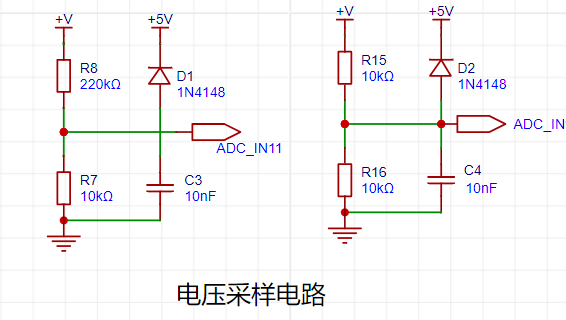
3. Voltage Sampling Circuit:
The voltage divider resistors in this project are designed to be 220K+10K, therefore the voltage division ratio is 22:1 (ADC_IN11).
The voltage divider resistor selection
is designed to measure the maximum voltage. For safety reasons, this project uses 30V (the actual maximum display value can be 99.9V or 100V).
The ADC reference voltage is 1.5V in this project, and this reference voltage can be configured through the program.
To reduce the power consumption of the sampling circuit, the low-side resistor (R7) is usually chosen as 10K based on experience.
Then, the high-side resistance of the voltage divider resistor can be calculated using the above parameters.
The required voltage division ratio is calculated, i.e., the ADC reference voltage. The input voltage is designed; using known parameters, 1.5V/30V = 0.05 can be calculated.
The high-side resistance is calculated as the low-side resistance/voltage division ratio; using known parameters, 10K/0.05 = 200K can be calculated.
A standard resistor is selected: a resistor slightly higher than the calculated value of 200K is chosen. We usually choose E24 series resistors; therefore, in this project, 220K, which is greater than 200K and closest to the calculated value, is selected.
If, in actual use, the voltage to be measured is lower than 2/3 of the module's design voltage (66V), the voltage divider resistor can be replaced and the program modified to improve measurement accuracy. The following example illustrates this:
Assuming the measured voltage is no higher than 24V and other parameters remain unchanged,
calculations show 1.5V/24V = 0.0625, 10K/0.0625 = 160K. 160K is a standard E24 resistor and can be directly selected, or a higher value 180K can be chosen with some redundancy.
If, in actual use, the voltage to be measured is higher than the module's 99V design voltage, a different resistor can be selected. To expand the voltage measurement range, you can choose to replace the voltage divider resistor or modify the reference voltage. The following example illustrates this:
Assuming the measured voltage is 160V, we can choose to increase the voltage reference to expand the range.
Given that the voltage division ratio of the selected resistor is 0.0145, we can calculate 160V * 0.0145 = 2.32V using the formula. Therefore, we can choose a 2.5V voltage reference to expand the range (increasing the range will reduce accuracy).
Considering the potential fluctuations in the measured power supply, a 10nF filter capacitor is connected in parallel with the low-side voltage divider resistor in the circuit design to improve measurement stability.
(Range switching )
In this project, an additional voltage sampling circuit was added. Therefore, we can discuss the significance of range switching for improving measurement accuracy. Multimeters often have multiple range settings to achieve more accurate measurements. By adjusting different ranges, the optimal measurement accuracy of the measured point within the corresponding range can be obtained.
This project requires a combination of hardware and software to implement this function. When we first use the ADC_IN11 channel mentioned earlier to measure voltages below 30V, if the measured voltage is within 0~3V, then we use the ADC_IN9 channel for measurement. At this time, due to the reduced voltage division ratio, the measurement accuracy is greatly improved. There are many ways to implement range switching; the development board design provides more design possibilities.
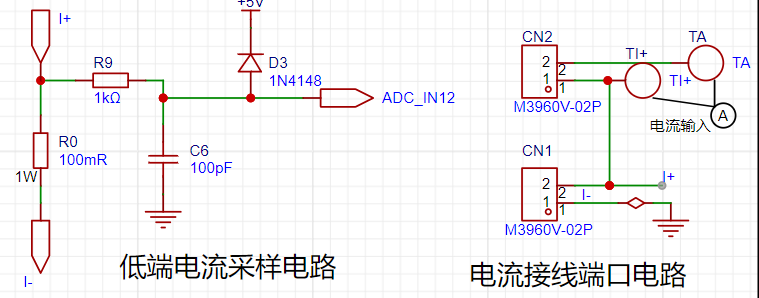
4. Current Sampling Circuit
This project uses a low-side current sampling circuit for current detection. When learning the common ground between the low-side of the sampling circuit and the development board's meter interface, please do not solder R0!!!

The design analysis
for this project involves a sampling current of 3A, and the selected sampling resistor (R0) is 100mΩ. The selection of the sampling resistor mainly needs to consider the following aspects:
the maximum value of the pre-designed measurement current;
the voltage difference caused by the 3A current sensing resistor in this project; and
the power dissipation of the current sensing resistor, which should generally not exceed 0.5V. A suitable package should be selected based on this parameter. Considering the power dissipation (temperature) issue under high current, a 1W metal wire-wound resistor package was chosen
. The voltage amplification factor across the current sensing resistor is also important. Since no operational amplifier is used to build the amplification circuit in this project, the factor is 1.
The current sensing resistor value can then be calculated using the above parameters
. Since no amplifier circuit is used, a larger sampling resistor is needed to obtain a higher measured voltage for measurement.
Considering that a larger resistor would result in a larger voltage drop and higher power consumption, an unlimited selection of a larger resistor is not feasible.
This project uses a 1W package resistor, corresponding to a power consumption of 1W.
Based on the above data, a 100mΩ current sensing resistor was selected. According to the formula, 3A * 100mΩ = 300mV, 900mW can be calculated.
To cope with different operating environments, especially high-current scenarios, the R0 resistor can be replaced with constantan wire or a shunt. The replacement can be selected according to the actual application scenario. For safety and educational purposes, this project will not discuss measurements exceeding 3A in detail, but the principle is the same.
5. Digital Tube Display
This project uses a digital tube as the display unit.
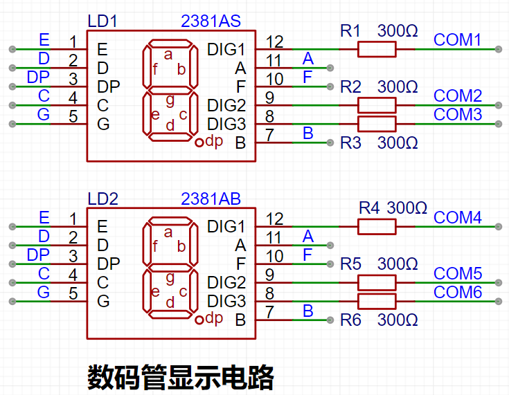
This project uses two 0.28-inch three-digit common-cathode LED displays as the display device. Compared to a display screen, LED displays offer better visibility in complex environments. The brightness of the LED displays can be increased by using smaller current-limiting resistors, depending on the specific needs of the application environment. Furthermore, LED displays have better mechanical properties and are not as easily damaged by external forces as display screens. They are widely used in industrial applications where stability and reliability are crucial. From a development board learning perspective, this makes it easier to learn electronic measurement principles and related development in a targeted manner.
In this project, actual testing showed that the current-limiting resistors (R1~R6) for the LED displays were configured to 300Ω. The corresponding brightness for both red and blue LED displays was good and the brightness was soft and not glaring.
Strictly speaking, the current-limiting resistors should be added to the segments; adding them to the digits would affect the display effect. Our actual design places them in the digits to save a few resistors, but the impact on the display is not significant. Therefore, we add them to the digits for convenience.
The
driving principle of LED displays mainly involves controlling the switching state of each segment of the LED display to display numbers, letters, or symbols. The following is a detailed explanation of the driving principle:
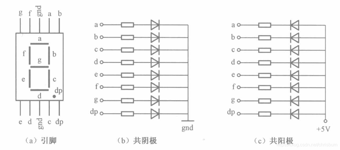
Basic Structure of a Digital Tube:
A digital tube typically consists of seven or eight LED segments (eight segments in this project). Each segment represents a part of the digital tube and can display numbers 0-9, letters AF, etc.
Digital tubes come in two types: common cathode and common anode. The difference lies in whether the common terminal COM (the end connecting all LEDs) is connected to the negative or positive terminal of the power supply.
Driving Methods:
Segment Selection: The desired number or character is displayed by controlling the on/off state of each segment of the digital tube. Each segment corresponds to a control signal; when the control signal is on, the segment lights up, and vice versa. (a, b, c, d, e, f, g, dp)
Bit Selection: The digital tube to be displayed is selected by controlling the bit lines of the digital tube. Bit line control sets the bit line of the digital tube to be displayed to a high level, and the bit lines of other digital tubes to a low level. By continuously switching the state of the bit lines, the display switching between multiple digital tubes can be achieved.
Driving Circuit:
The driving circuit for a digital tube can be implemented using hardware circuits, such as integrated circuits like digital signal processors (DSPs), microcontrollers (MCUs), or shift registers, to generate control signals suitable for the LEDs.
These control signals can be in the form of pulse width modulation (PWM) signals, serial data signals, etc. By controlling the frequency, width, and amplitude of these signals, the brightness of the digital tube can be controlled, thereby displaying the desired numbers or letters.
Software Control:
In addition to hardware driving circuits, the driving of digital tubes can also be implemented through software control. By programming to generate control signals suitable for the digital tubes, more flexible and complex display effects can be achieved, such as scrolling or alternating display of numbers.
Driving Common Cathode and Common Anode Digital Tubes:
For common cathode digital tubes, the common cathode pin is connected to the negative terminal of the power supply, and the control pin is connected to the output pin of the control chip. When a certain number needs to be displayed, the control chip outputs the corresponding encoded signal to the control pin, causing the corresponding LED segment to light up.
For common anode digital tubes, the working principle is similar to that of common cathode digital tubes, except that the common anode pin is connected to the positive terminal of the power supply, and the control pin is connected to the output pin of the control chip.
Encoded Display:
In order for the digital tube to display the corresponding numbers or characters, the segment data port must output the corresponding character encoding. For example, to display the number "0", the character code for a common anode seven-segment display is 11000000B (i.e., C0H), while the character code for a common cathode seven-segment display is 00111111B (i.e., 3FH). The specific code depends on the actual seven-segment display.
Dynamic and Static Display:
Seven-segment displays can use either static or dynamic display methods. In static display, each of the eight segments of each seven-segment display is connected to an 8-bit I/O port address. As long as the I/O port outputs a segment code, the corresponding character is displayed and remains unchanged. Dynamic display, on the other hand, lights up each segment of the seven-segment display one by one, achieving simultaneous visual display through rapid switching.
In summary, the driving principle of seven-segment displays is to control the switching state of each segment of the seven-segment display to display numbers, letters, or symbols, and to achieve display switching between multiple seven-segment displays through segment selection and digit selection. Furthermore, the driving of seven-segment displays can be implemented through hardware circuits or software control, and common cathode or common anode seven-segment displays can be selected as needed.
This project actually uses dynamic scanning display to drive the seven-segment display.
To estimate the current required for the digital tube display,
this project actually uses dynamic scanning to drive the digital tubes. Therefore, at any given time, only a maximum of 8 segments of the digital tube (or LEDs) can be lit, or in other words, only one digit can be lit. According to the design, the required driving current is approximately 11mA, which is the high-level voltage of the I/O port: 3.3V ÷ 300Ω.
At this point, it is important to ensure that the selected MCU has sufficient current-source/current-sinking capability.
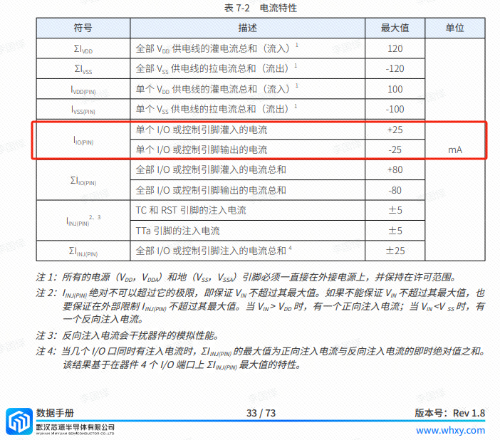
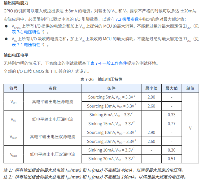
Analysis of the datasheet shows that the CW32 has no issues. (Some chips do not work.)
6. LED Indicators
This project additionally designed a power indicator and an I/O operation indicator.
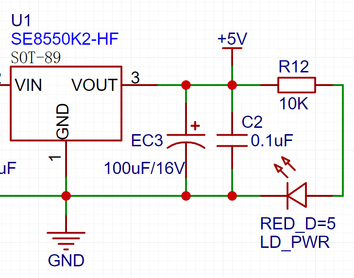
LD_PWR is the power operation indicator

. Since the chip's I/O often has a greater current sinking capability than a current pulling capability, LED1 is designed to be active low (on).
To reduce the current consumption of the LED, some LED brightness is sacrificed, the number of component parameters is reduced, and the current-limiting resistor for the LED is selected as 10K.
7. Button Circuit Design

There are various design methods for the button control circuit. Thanks to the fact that the CW32's I/O port can be configured with pull-up and pull-down resistors internally, the button control circuit on the outside of the chip does not need to be configured. One end of the button is connected to the MCU's I/O, and the other end is grounded. When the button is pressed, the I/O is pulled low.
8. TL431 Circuit Design for Voltage Measurement and Calibration:
This project adds an extra TL431 circuit to provide a 2.5V reference voltage. This can be used to provide an external voltage reference for the chip to calibrate the AD converter. From a product design perspective, due to the inherent ADC performance advantages of the CW32, this circuit is not necessary. This circuit is designed on the development board to learn the relevant application principles.

The TL431 is a relatively "old" device, a classic, and widely used one, still found in many electronic products.
Many beginners may be encountering this device for the first time, so we will briefly explain its principles to help everyone better apply the TL431.
TI defines it as a "Precision Programmable Reference." On the first page of the references, we can focus on several key characteristics.
Precision: Precision indicates that its output voltage is very accurate. I used a ±0.5% accuracy TL431, which measured 2.495V on the board at room temperature. Compared to common Zener diodes, the accuracy is vastly different. In the application circuit diagram, the TL431 is represented by a Zener diode symbol.
Adjustable Output Voltage: The adjustable output voltage is between Vref and 36V. In our project, we use the output Vref voltage, which is approximately 2.5V. Therefore, we use 2.5V in the description, which is approximately equal to Vref.
Sinking Current Capability: This refers to how much current the output voltage pin can provide. This is greatly influenced by the resistance value (R13) in the application circuit. It should not be less than 1mA. If there is no need for sinking current, do not design the current to be too high, as this will cause unnecessary power consumption.
Voltage and Ammeter Project.zip
8d45a207621b7cfefc9ac88aa7c8801d.mp4
PDF_Voltage and Current Meter Based on the CW32F030C8T6 Development Board by Diwenxing.zip
Altium-based CW32F030C8T6 development board voltage and current meter.zip
PADS_Voltage and Current Meter Based on the CW32F030C8T6 Development Board.zip
BOM_Voltage and Current Meter Based on the CW32F030C8T6 Development Board of the GeoStar.xlsx
92667
Voltmeter and Ammeter Training Camp
A voltage and current meter based on the CW32 core.
This project uses the CW32F030C8T6 as its core, enabling adjustable voltage and current measurements.
Hardware Design:
1. Power Supply Circuit:
This project uses an LDO as the power supply. Considering that most voltmeter products are used in industrial scenarios with 24V or 36V power supplies, the SE8550K2 with a maximum input voltage of 40V was chosen as the power supply. The main reason for not using a DC-DC buck converter to handle large voltage drops is to avoid introducing DC-DC ripple interference during the design process; a secondary reason is to reduce project costs.
2. MCU Selection:
Key Advantages of CW32 in this Project
- Wide Operating Temperature Range: -40~105℃
Wide Operating Voltage: 1.65V~5.5V (STM32 only supports 3.3V systems)
Superior Interference Resistance: HBM ESD 8KV All ESD reliability reaches the highest international standard level (STM32 ESD 2KV)
Project Focus - Better ADC: 12-bit high-speed ADC, achieving ±1.0LSB INL 11.3ENOB Multiple Vref Reference Voltages... (STM32 only supports VDD=Vref)
Stable and Reliable eFLASH Technology. (Flash0 pending)
3. Voltage Sampling Circuit Voltage
Divider Resistor Selection
and Design: The maximum value of the measured voltage is 30V for safety reasons (the actual maximum display value can be 99.9V or 100V);
ADC reference voltage is 1.5V in this project, which can be configured through the program;
power consumption, in order to reduce the power consumption of the sampling circuit, the low-side resistor (R7) is usually selected as 10K based on experience;
then the high-side resistance of the voltage divider resistor can be calculated using the above parameters:
Calculate the required voltage division ratio: i.e., ADC reference voltage: Design input voltage, which can be calculated using known parameters as 1.5V/30V=0.05
Calculate the high-side resistance: i.e., low-side resistance/voltage division ratio, which can be calculated using known parameters as 10K/0.05=200K
Select a standard resistor: Select a resistor slightly higher than the calculated value, which is 200K. We usually choose E24 series resistors, so in this project, we choose 220K, which is greater than 200K and closest to it.
If, in actual use, the voltage to be measured is lower than 2/3 of the module's design voltage (66V), the voltage divider resistor can be replaced and the program modified to improve measurement accuracy. The following example illustrates this:
Assuming the measured voltage is no higher than 24V and other parameters remain unchanged,
calculations show 1.5V/24V = 0.0625, 10K/0.0625 = 160K. 160K is a standard E24 resistor and can be directly selected, or a higher value 180K can be chosen with some redundancy.
If, in actual use, the voltage to be measured is higher than the module's 99V design voltage, a different resistor can be selected. To achieve a wider voltage measurement range, you can choose to replace the voltage divider resistor or modify the reference voltage. The following example illustrates this:
Assuming the measured voltage is 160V, we can choose to increase the voltage reference to expand the range.
Given that the voltage division ratio of the selected resistor is 0.0145, we can calculate 160V * 0.0145 = 2.32V using the formula. Therefore, we can choose a 2.5V voltage reference to increase the range (increasing the range will reduce accuracy).
Considering the potential fluctuations in the measured power supply, a 10nF filter capacitor is connected in parallel with the low-side voltage divider resistor in the circuit design to improve measurement stability.
4. Current Sampling Circuit
The sampling current designed for this project is 3A, and the selected sampling resistor (R0) is 100mΩ.
The selection of the sampling resistor mainly needs to consider the following aspects:
the maximum value of the pre-designed measurement current; in this project,
the voltage difference caused by the 3A current sensing resistor is generally not recommended to exceed 0.5V
; the power consumption of the current sensing resistor should be selected based on this parameter. Considering the power consumption (temperature) issue under high current, a 1W packaged metal wire-wound resistor was selected.
The voltage amplification factor across the current sensing resistor: No operational amplifier was used to build the amplification circuit in this project, so the factor is 1.
The current sensing resistor value can then be calculated using the above parameters
. The project does not use an amplifier circuit, therefore a larger sampling resistor is needed to obtain a higher measured voltage for measurement.
Considering that a larger resistor will result in a larger voltage drop and higher power consumption, a larger resistor cannot be selected indiscriminately.
This project uses a 1W package resistor, corresponding to a temperature rise power of 1W.
Based on the above data, a 100mΩ current sensing resistor was selected. According to the formula, 3A * 100mΩ = 300mV, 900mW can be calculated.
To cope with different usage environments, especially high current scenarios, the R0 resistor can be replaced with constantan wire or a shunt. The replacement can be selected according to the actual usage scenario. For safety and educational purposes, this project will not discuss the range exceeding 3A in detail, but the principle is the same.
5. Digital Tube Display Circuit
This project uses two 0.28-inch three-digit common cathode digital tubes as display devices. Compared with a display screen, digital tubes have better recognition in complex environments. According to the actual usage environment requirements, smaller current limiting resistors can be used to achieve higher digital tube brightness. On the other hand, digital tubes have better mechanical properties and are not as easily damaged by external forces as display screens. In industrial applications requiring stability and reliability, this technology is widely adopted. From a development learning perspective, it facilitates more targeted learning of electronic measurement principles and related development.
In this project, after actual testing, the current-limiting resistors (R1~R6) of the digital tube were configured to 300Ω. The corresponding brightness, whether for red or blue digital tubes, exhibited good visibility and a soft, non-glaring brightness.
6. Indicator Circuit:
Since chip I/O often has a greater current-sinking capability than current-pull capability, LED1 is designed to be active low (on). To reduce LED current consumption, some LED brightness was sacrificed, and the number of component parameters was reduced; the LED current-limiting resistor was chosen to be 10K.
7. Button Circuit Design:
There are various design methods for button control circuits. Thanks to the CW32's internal I/O ports which can be configured with pull-up and pull-down resistors, the button control circuit on the chip's periphery does not require configuration. One end of the button is connected to the MCU's I/O, and the other end is grounded. When the button is pressed, the I/O is pulled low.
8. TL431 Circuit Design for Voltage Measurement and Calibration. Understanding the TL431's operating
principle
is beneficial for quickly understanding its different applications.
The functional block diagram can be found in TI's datasheet; we only need to analyze its equivalent schematic.
The core of the 431 is an operational amplifier, which acts as a comparator in the circuit. Internally, the chip has a voltage Vref (approximately 2.5V) applied to the inverting input of the comparator. A voltage is input to REF at the non-inverting input of the comparator. When this voltage is greater than Vref, the comparator outputs a high level, enabling the transistor and connecting the CATHODE (cathode) and ANODE (anode) terminals. If REF and CATHODE are at the same potential (connected), the potential at REF is pulled low. When the potential at REF drops below Vref, the comparator outputs a low level, the transistor turns off, and the potential at REF rises back up. When it rises above Vref, the above process continues, and so on. Because the hardware response speed is extremely fast, the voltage at REF is almost equal to Vref.
8. Schematic and PCB Design Considerations:
Pads and Reinforcement.
In PCB design, I often use elongated oval pads for through-hole components to increase the contact area between the solder, soldering iron, and the pad, making soldering easier. Meanwhile, a silkscreen layer is designed as a separator between closely spaced pads. On actual circuit boards, the raised silkscreen layer significantly reduces solder bridging during soldering. This method is widely used in product design to improve production yield.

Solid filler is used to reinforce pads and some traces, preventing scratches and damage to the circuit board and pad detachment during use. In fact, given the excellent quality of JLCPCB PCB materials, this design is unnecessary in double-layer board designs; the author's initial intention was primarily to demonstrate and broaden the user's perspective. Teardrop
tools can be used for reinforcement in double-layer board designs.
The Kelvin connection method for current sampling resistors
eliminates the influence of line resistance and contact resistance on measurement results. In high-precision sampling applications, dedicated four-wire sampling resistors are also available, but this will not be discussed here.
Silkscreen printing and manufacturing processes :
Silkscreen printing on general PCBs is sprayed on, so when the font size is small and the line width is thick, blurring may occur, leading to unclear markings. It is recommended to choose appropriate silkscreen font size and line width, as different silkscreen fonts have different effects. Choosing a suitable font will result in better printing performance at the same line width and font size.
DRC design considerations:
Power supply traces should be as wide as possible, approximately 20-60 mil.
Ordinary signal lines: around 10 mil .
ADC signal traces: 10 mil or 8 mil. Too wide a trace may affect signal integrity when the line is too long.
Since high-speed circuit design is not involved, the 3W principle is not emphasized here.
Standardize component pin spacing: such as using imperial units, utilizing the grid and grid functions of EDA software, and arranging component positions and traces reasonably.
Software program design:
GPIO driver and code configuration are relatively simple, so details are omitted here.
1. Digital tube driver:
Combining the schematic diagram, the approach to driving the digital tube display is: first, number the pins represented by A, B, C, D, E, F, and G from low to high, and list the segment code values of the numbers to be displayed. For example, to display the number 5, the segment code value is 0x6d, which is represented in binary as 01101101. This means G is set to 1, F to 1, E to 0, D to 1, C to 1, B to 0, A to 1, and the highest bit is the value of DP. Storing the numbers to be displayed as segment code values in an array for later retrieval simplifies the program. Then, using a loop combined with a switch statement, the on/off status of A, B, C, D, E, F, and G is calculated individually. Determining the segment code value before selecting the bit code avoids insufficient display effect due to the microcontroller's program execution time.
Dynamic scanning display means sending segment codes and bit codes to each digit of the LED display in turn, utilizing the afterglow of the LEDs and the persistence of vision to make the human eye perceive that all digits are displaying simultaneously. Having understood the principle, to make the three digits of the voltmeter and ammeter display different values simultaneously, we need to use the CW32's timer function, performing the display refresh action within the timer's interrupt service routine.
2. The
CW32F030 uses a successive approximation 12-bit ADC for sampling. Successive approximation ADCs operate on a common principle: they approximate the digital representation of the input signal by comparing the magnitude of the analog signal with a reference voltage. In a successive approximation ADC, the input signal and reference voltage are fed into a differential amplifier to generate a differential voltage. This differential voltage is then input to a successive approximation quantizer, which compares it to a series of reference voltages in a progressively decreasing manner. Specifically, at each approximation stage, the quantizer compares the input signal with an intermediate voltage point, using the reference voltage above or below that point as the reference voltage for the next approximation stage. This process continues until the quantizer approximates the final digital output value.
dian_ya_dian_liu_biao.zip
Homemade Voltmeter and Ammeter.mp4
PDF_Voltmeter and Ammeter Training Camp.zip
Altium_Voltage and Ammeter Training Camp.zip
PADS_Voltmeter & Ammeter Training Camp.zip
BOM_Voltage and Ammeter Training Camp.xlsx
92668
Voltmeter and Ammeter Training Camp
CW32-based digital voltage and current meter
This project is a digital voltage and current meter based on the CW32 microcontroller. It primarily uses the CW32F030 microcontroller as the main control chip and includes modules such as a power supply circuit, an ADC (Analog-to-Digital Converter) circuit, a voltage acquisition circuit, a current acquisition circuit, a digital tube display circuit, LED indicators, and button circuits. It can realize the function of voltage and current acquisition and display.
1. ADC Circuit:
The ADC (Analog-to-Digital Converter) is an indispensable key component in electronic systems. It converts continuous analog signals into digital signals, enabling digital processing and analysis. ADCs play an important role in signal conversion, measurement and data acquisition, control system input, and communication and signal processing. Their widespread application promotes the intelligent and precise control of electronic equipment in various industries and is one of the key factors driving modern technological progress.
2. Power Supply Circuit:
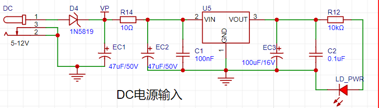
It uses a DC power supply and an LDO (Low Voltage Regulator). This project selected the SE8550K2, which has a maximum input voltage of 40V, as the power supply. The main reason this project did not use a DC-DC step-down circuit to handle large voltage differences was to avoid introducing DC-DC ripple interference during the design process; a secondary reason was to reduce project costs.
3. Voltage Acquisition Circuit:
Implementing this function in this project requires a combination of hardware and software. When we first use the ADC_IN11 channel mentioned earlier to measure voltages within 30V, if the measured voltage is within 0~3V, then we use the ADC_IN9 channel for measurement. At this time, due to the reduced voltage division ratio, the measurement accuracy is greatly improved.
4. Current Acquisition Circuit:
The sampling current designed for this project is 3A, and the selected sampling resistor (R0) is 100mΩ. The selection of the sampling resistor mainly needs to consider the following aspects:
the maximum value of the pre-designed measurement current; in this project,
the voltage difference caused by the 3A current sensing resistor is generally not recommended to exceed 0.5V
; the power consumption of the current sensing resistor should be selected based on this parameter. Considering the power consumption (temperature) issue under high current, a 1W packaged metal wire-wound resistor was selected.
The voltage amplification factor across the current sensing resistor: No operational amplifier was used to build the amplification circuit in this project, so the factor is 1.
The current sensing resistor value can then be calculated using the above parameters
. The project does not use an amplifier circuit, therefore a larger sampling resistor is needed to obtain a higher measured voltage for measurement.
Considering that a larger resistor would result in a larger voltage drop and higher power consumption, an unlimited selection of a larger resistor is not feasible .
This project uses a 1W package resistor, corresponding to a power consumption of 1W.
Based on the above data, a 100mΩ current sensing resistor was selected. According to the formula, 3A * 100mΩ = 300mV, 900mW can be calculated.
To cope with different operating environments, especially high-current scenarios, the R0 resistor can be replaced with constantan wire or a shunt. The choice of alternative can be made based on the actual application scenario. For safety and educational purposes, this project will not discuss measurements exceeding 3A, but the principle remains the same.
5. Overall Schematic Diagram
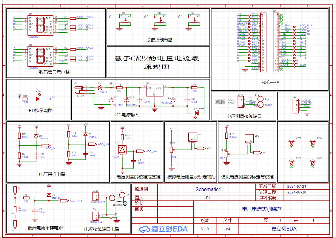
6. PCB Circuit Display

PDF_Voltmeter and Ammeter Training Camp.zip
Altium_Voltage and Ammeter Training Camp.zip
PADS_Voltmeter & Ammeter Training Camp.zip
BOM_Voltage and Ammeter Training Camp.xlsx
92669
Digital voltage and current meter with LCSC GeoStar development board as the main controller
The digital current and voltage meter, with the LCSC GeoStar development board as the main controller, uses a voltage divider circuit to achieve high voltage acquisition.
#LCSC Training Camp#
Because I really wanted to build a drone myself, but as a complete beginner, I had absolutely no knowledge of electronic circuit hardware and software, so I joined the #LCSC Training Camp# to accumulate knowledge. (Since this is my first time doing this, please give me your feedback on any shortcomings.)
I. Hardware The
hardware part referenced the "CW32 Digital Voltmeter and Ammeter Training Camp Project Tutorial Document"; I changed the through-hole components to surface-mount components. Every step in the document is very detailed, making it easy for beginners to learn without having to search for tutorials everywhere. I really love it! LCSC is awesome!!!

1. Power Supply Circuit
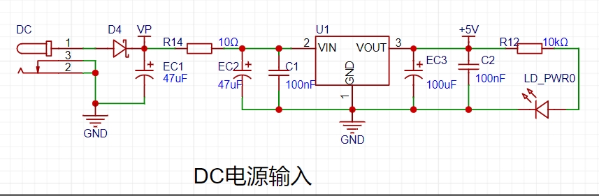
This project uses a low-cost LDO low-dropout linear regulator as the power supply.
2. Main Controller:

This project uses the LCSC CW32F030C8Tx development board (core board) as the main controller.
Advantages of the CW32:
- Wide operating temperature range: -40~105℃
- Wide operating voltage range: 1.65V~5.5V
- Strong anti-interference: HBM ESD 8KV, all ESD reliability reaches the highest international standard level
- Key focus of this project - Better ADC: 12-bit high-speed ADC, achieving ±1.0LSB INL 11.3ENOB, multiple Vref reference voltages... ...
- Stable and reliable eFLASH technology.
3. Voltage Sampling Circuit:

The voltage divider resistors used in this circuit are 220K+10K.
Voltage Divider Resistor Selection
: 1. Maximum design measurement voltage: For safety reasons, this project uses 30V (actual maximum display can be 99.9V or 100V);
2. ADC reference voltage: This project uses 1.5V, which can be configured through the program;
3. Power consumption: To reduce the power consumption of the sampling circuit, the low-side resistor (R7) is usually selected as 10K based on experience;
then the high-side resistance of the voltage divider resistor can be calculated using the above parameters:
1. Calculate the required voltage division ratio: i.e., ADC reference voltage: design input voltage, which can be calculated using known parameters as 1.5V/30V=0.05
2. Calculate the high-side resistance: i.e., low-side resistance/voltage division ratio, which can be calculated using known parameters as 10K/0.05=200K
3. Select a standard resistor: Select a resistor slightly higher than the calculated value, which is 200K. We usually choose E24 series resistors, so in this project, we choose 220K, which is greater than 200K and closest to it.
4. Current Sampling Circuit:

The sampling current designed for this project is 3A, and the selected sampling resistor (R0) is 100mΩ.
The following aspects should be considered when selecting the sampling resistor:
1. The maximum value of the pre-designed measurement current, which is 3A in this project
. 2. The voltage difference caused by the current sensing resistor; it is generally not recommended to exceed 0.5V.
3. The power consumption of the current sensing resistor; a suitable package should be selected based on this parameter. Considering the power consumption (temperature) issue under high current, a 1W metal wire-wound resistor was selected in this project.
4. The voltage amplification factor across the current sensing resistor: No operational amplifier is used to build the amplification circuit in this project, so the factor is 1.
The current sensing resistor value can then be calculated using the above parameters.
1. Since this project does not use an amplifier circuit, a larger sampling resistor is needed to obtain a higher measured voltage for measurement.
2. Considering that a larger resistor will result in a larger voltage drop and higher power consumption, an unlimited selection of a larger resistor is not advisable.
3. This project uses a 1W package resistor, corresponding to a power consumption of 1W. Based on
the above data, a 100mΩ current-sensing resistor was selected. According to the formula, 3A * 100mΩ = 300mV, 900mW can be calculated.
5. Display Unit:
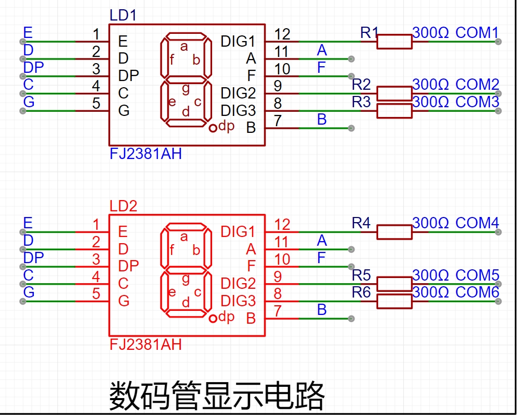
This project uses two simpler and more stable three-digit common-cathode LED displays as the display device.
In this project, the current-limiting resistors (R1~R6) of the LED displays are configured to 300Ω. The corresponding brightness, whether for red or blue LED displays, has good visibility and is soft and not dazzling.
6. Status Indicators:
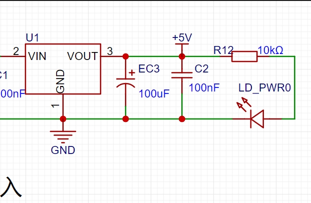
LD_PWR0 is the power indicator ,

and LED1 is the working indicator.
To reduce the current consumption of the LEDs, some LED brightness is sacrificed, and the number of device parameters is reduced. The current-limiting resistor for the LEDs is selected as 10K.
7. Button Control Circuit

The button control circuit can be designed in various ways. Thanks to the CW32's internal I/O ports which can be configured with pull-up and pull-down resistors, the button control circuit on the outside of the chip does not need to be configured. One end of the button is connected to the MCU's I/O, and the other end is grounded. When the button is pressed, the I/O is pulled low.
a69a56f470cb1cebb7d54e06814110a5.mp4
1859cea5ad4c32978ae87231b80b664d.mp4
Voltmeter and Ammeter Program 7.3 (15V 5V 0V 1.5A 0.5A 0A Calibration Parameters Saved).zip
PDF_Digital voltage and current meter based on the LCSC GeoStar development board.zip
Altium digital voltage and current meter based on the LCSC GeoStar development board. (zip file)
PADS digital voltage and current meter based on the LCSC GeoStar development board. (zip file)
BOM - Digital Voltage and Current Meter Based on LCSC GeoStar Development Board.xlsx
92670
Simple Digital Voltmeter and Ammeter
This is a poor imitation of an open-source project from JLCPCB's CW voltage and current meter training camp, a shining example of domestic hardware. It has its shortcomings and problems; I would appreciate your kind advice.


Project Overview:
This project is an open-source project from the LCSC Voltage and Current Meter Training Camp. Based on the LCSC CW32 development board, it's an expansion board design for a voltage and current meter, capable of detecting externally input voltage and current. Theoretically, the voltage range is 0-100V, and the current range is 0-3A.
Project Parameters
: Voltage range: 0-100V (not recommended to exceed 30V for safety);
Current range: 0-3A; The current sensing resistor can be adjusted or replaced with an amplifier to increase the range;
6-36V input, standard DC interface, LDO power supply system, nominal value 12V;
Three buttons, events can be customized according to the program;
The design includes an adjustable reference voltage for quick testing and calibration.
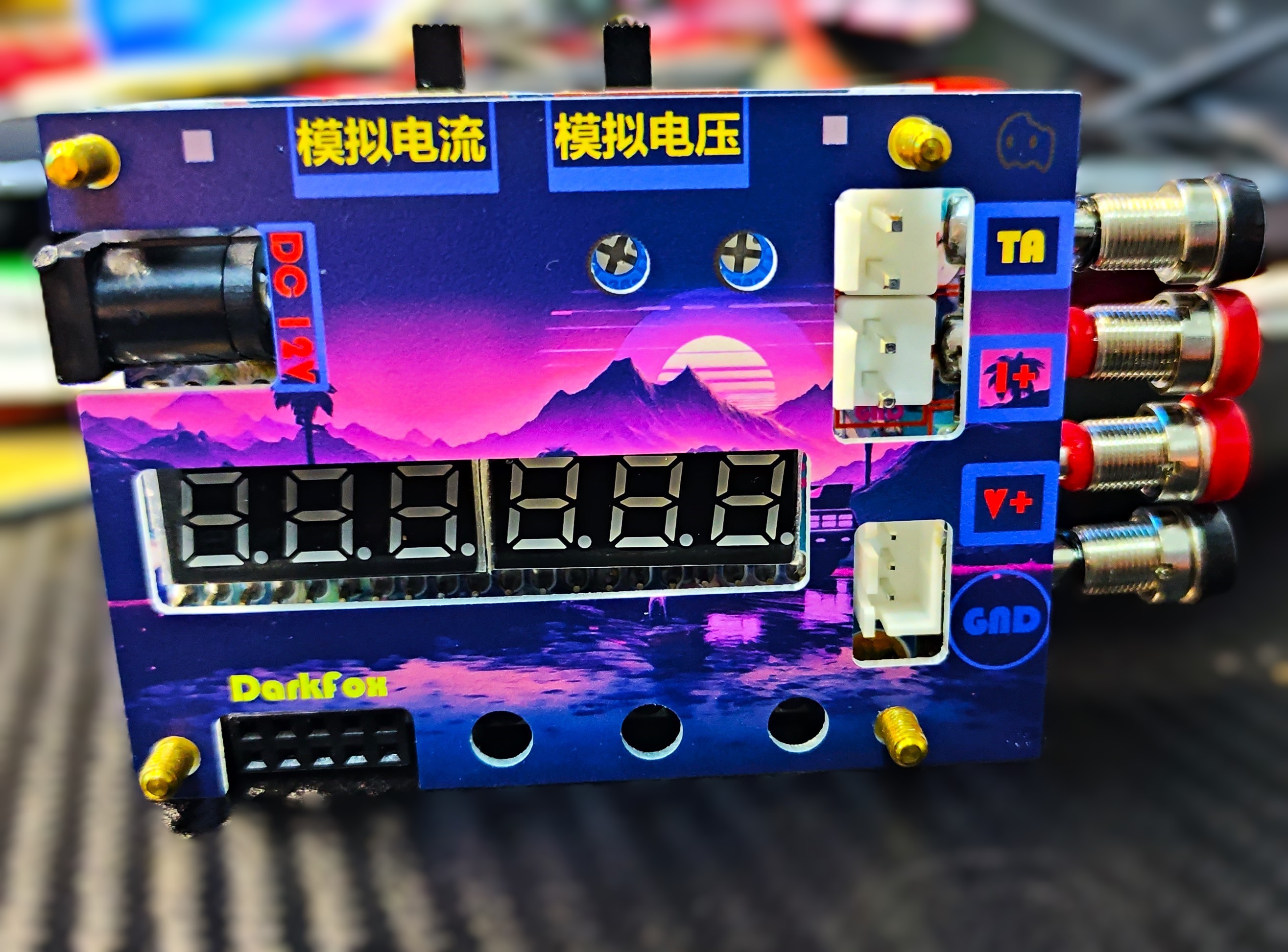
LED power indicator and operation indicator physical verification
: Voltage verification:
I only have a small USB adjustable voltage source on hand, so I used it with a power bank for testing;
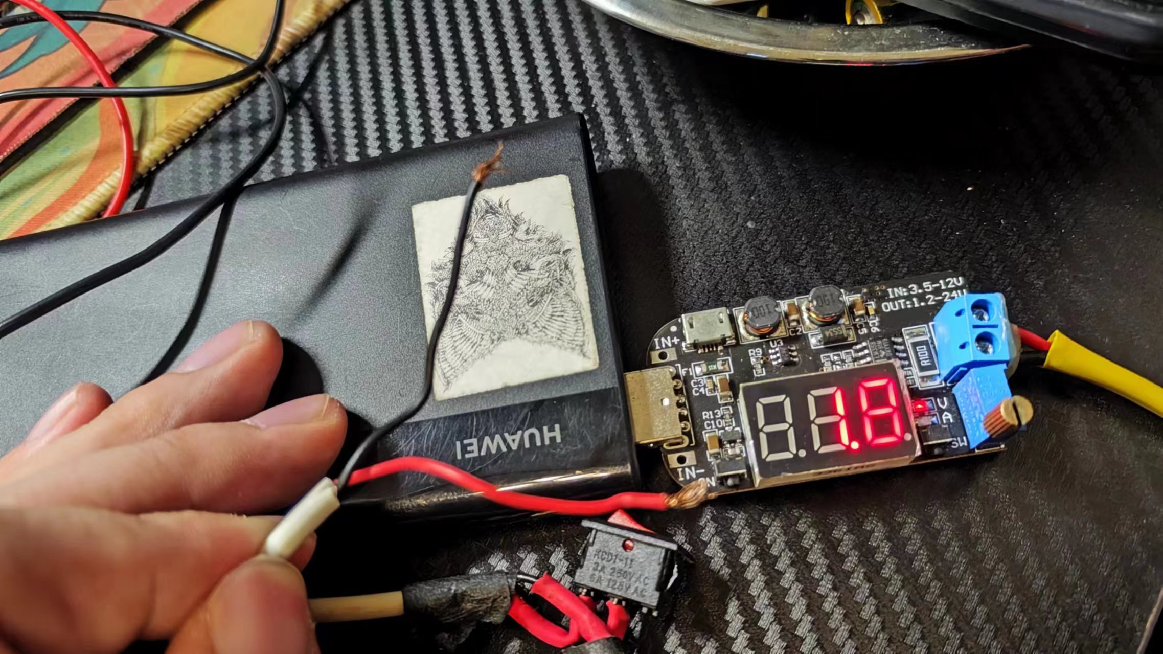
because this small USB voltage source costs only a few dollars and the reading is inaccurate, we used a regular multimeter as a reference;
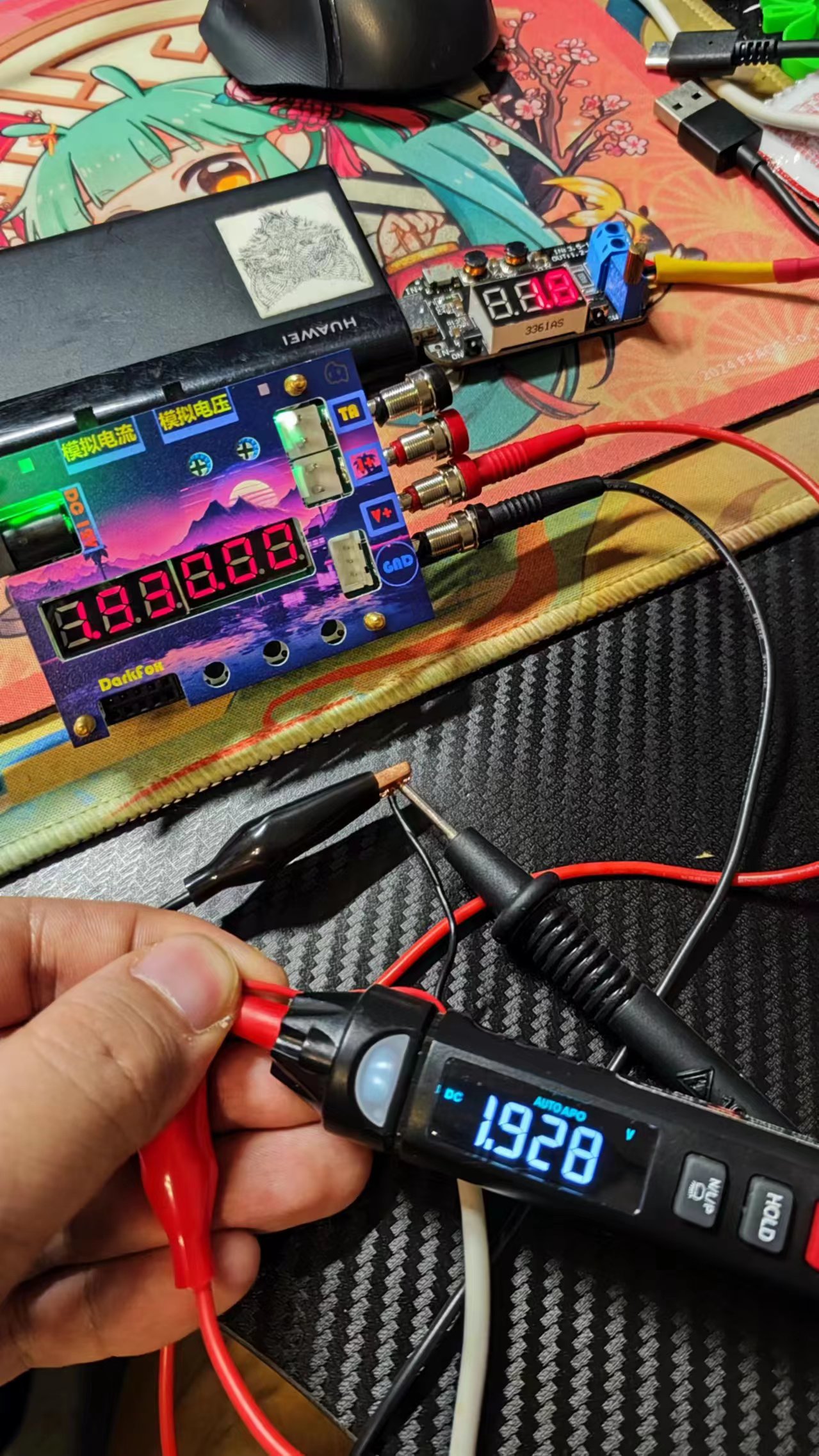
after connecting the cables, we can see that the readings are basically consistent;
Current verification:
I don't have a current source on hand, so I used a voltage source and an LED to form a rough constant current source; under low current conditions, the accuracy of this USB power source is slightly higher, because my cheap multimeter doesn't have a current measurement mode, so I used this as a rough reference; we can see that the parameters are basically consistent;
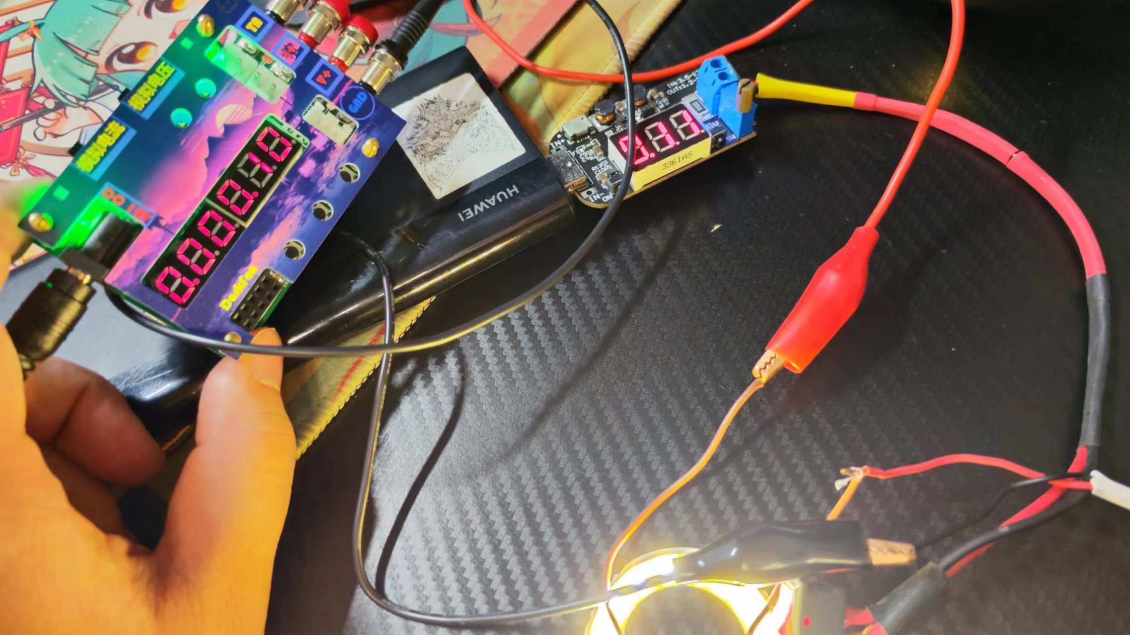
verification is now complete;
Hardware design
1. Power supply circuit A
suitable power supply is the solid foundation of a good circuit, and choosing a good power supply system is very important;
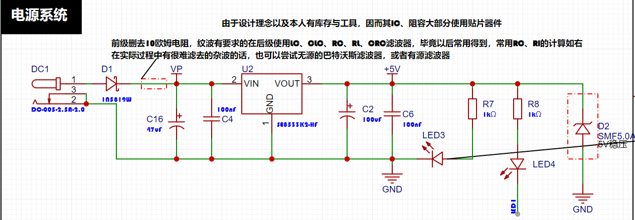
The LDO (Low Dropout Linear Regulator)
project uses a low dropout linear regulator (LDO) as the power supply solution. Voltmeters are typically used in industrial environments where the supply voltage is often 24V or 36V. Therefore, the project selected the SE8550K2 LDO, which has a maximum input voltage of 40V to meet the requirements of these applications. A DC-DC step-down circuit was not used in this project, primarily to avoid ripple interference that might be introduced into the design. Ripple interference can affect the measurement accuracy and stability of the voltmeter. Secondly, omitting a DC-DC step-down circuit also reduces the overall project cost, which is an important consideration in cost-sensitive applications.
However, LDOs generate significant heat under large voltage differentials, so I personally do not recommend using excessively high power supply input voltages. I suggest using the nominal value of 12V for this solution. If you want to use a higher voltage, you can refer to the following circuit:
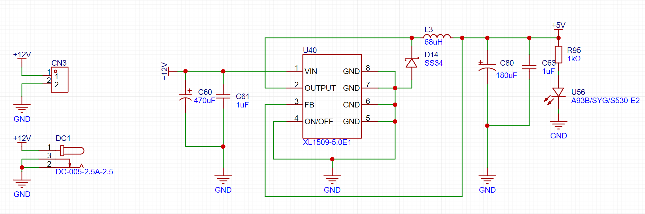
This circuit has been verified by me multiple times and is feasible. Under strict ripple control conditions, I suggest adding a Π-type filter or similar in the subsequent stage.
2. Voltage Sampling Circuit : The
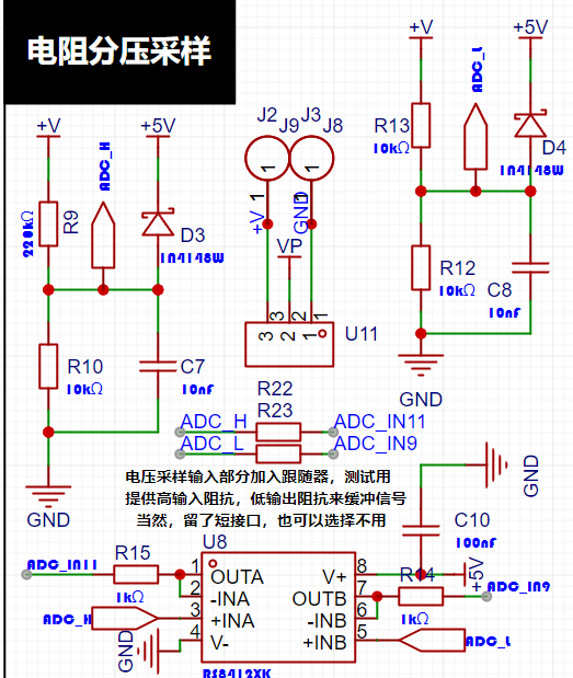
voltage sampling uses the simplest resistor voltage divider sampling, calculated as follows:
The maximum value of the designed voltage to be measured is 30V for safety reasons (the actual maximum display can be 99.9V or 100V).
The ADC reference voltage is 1.5V in this project, and this reference voltage can be configured through the program.
To reduce power consumption in the sampling circuit, the low-side resistor (R10) is typically chosen as 10K based on experience.
The high-side resistance of the voltage divider can then be calculated using the above parameters.
The required voltage division ratio is calculated, i.e., the ADC reference voltage. The input voltage is calculated as 1.5V/30V = 0.05 using known parameters.
The high-side resistance is calculated as low-side resistance/voltage division ratio, which is 10K/0.05 = 200K using known parameters.
A standard resistor is selected: a resistor slightly higher than the calculated value of 200K is chosen. We typically choose E24 series resistors, so in this project, we choose 220K, which is greater than 200K and closest to the calculated value.
Since this project is for experimental verification and does not require very high precision, these resistors do not need to be of high precision. If high precision is required, it is recommended to use high-precision resistors. The Runshi RS8412 dual-channel op-amp is used as a follower; this is not a cost-saving measure, but rather an optimization of the signal.
3. Current Sampling Circuit Design and Analysis:

The current sampling resistor parameters mainly need to consider the following aspects:
the maximum value of the pre-designed measurement current. In this project,
the voltage difference caused by the 3A current sensing resistor is generally not recommended to exceed 0.5V.
The power consumption of the current sensing resistor should be selected according to this parameter. Considering the power consumption (temperature) problem under high current, a 1.25W metal chip resistor was selected in this project.
The voltage amplification factor across the current sensing resistor: No operational amplifier was used to build the amplification circuit in this project, so the factor is 1.
Then the current sensing resistance value can be calculated from the above parameters. Selection:
Based on the above data, a 100mΩ current sensing resistor was selected in this project. According to the formula, 3A*100mΩ=300mV, 900mW can be calculated.
If different usage environments are required, especially for scenarios with large currents, the resistor can be replaced with constantan wire or a shunt, or an amplifier can be used to amplify the signal.
4. Digital Tube Display:
This project uses a digital tube as the display unit.

This project uses two 0.28-inch three-digit common-cathode LED displays as the display device. Compared to a display screen, LED displays offer better visibility in complex environments. The brightness of the LED displays can be increased by using smaller current-limiting resistors to meet the specific needs of the application environment. Furthermore, LED displays have better mechanical properties and are not as easily damaged by external forces as display screens. They are widely used in industrial applications where stability and reliability are crucial. From a development board learning perspective, this makes it easier to learn electronic measurement principles and related development in a targeted manner.
In this project, actual testing showed that a 300Ω current-limiting resistor for the LED displays resulted in good visibility for both red and blue LED displays, with a soft and non-glaring brightness.
5. LED Indicators:
This project added a power indicator and an I/O operation indicator.
Regarding LED brightness: Maximum LED brightness is very glaring, and maximum brightness output is not recommended.
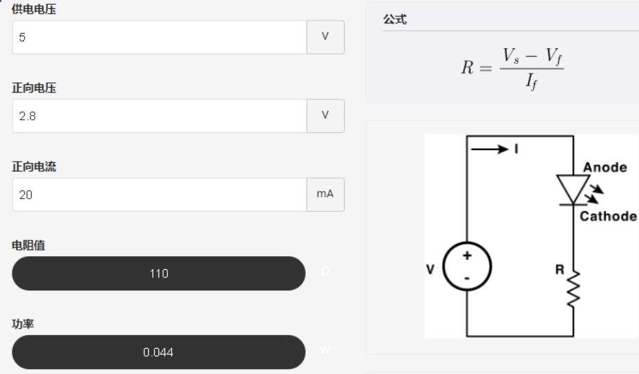
After determining the required light intensity, adding a current-limiting resistor after calculation can reduce its brightness. Alternatively, PWM control can be used to control its brightness.
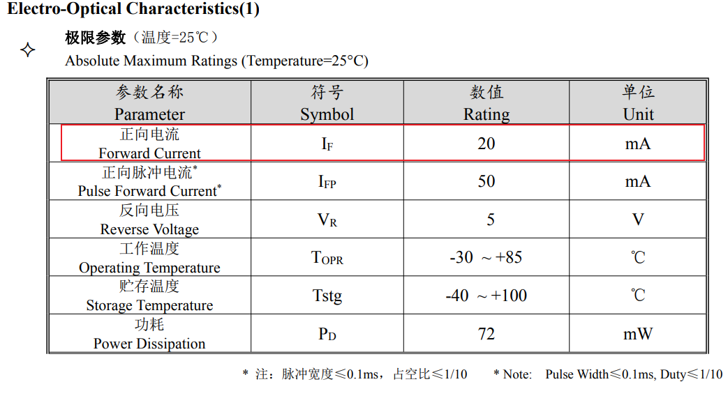
We can perform simple calculations based on the LED light's datasheet. According to the datasheet, we can quickly locate the forward current and forward voltage. Then, based on the current-intensity curve, we can obtain the current limiting value required for the desired brightness, and then deduce the value of the current-limiting resistor. For example, if we want the light to output with a relative intensity of 1:


6. Button circuit design:
Capacitor physical debouncing;
the microcontroller detects high and low levels to determine if the button is pressed;

7. TL431 circuit design for voltage measurement calibration:
This project adds an extra TL431 circuit to provide a 2.5V reference voltage, which can be used to provide an external voltage reference for the chip to calibrate the AD converter;

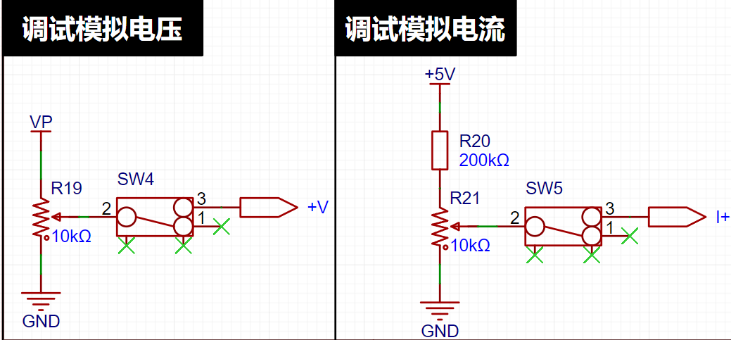
8. Onboard voltage measurement.
To facilitate circuit debugging, a simple resistor voltage divider circuit was added to the sampling end; the reference value can be adjusted by rotating the rheostat; the parameter is controlled by a switch to connect to the circuit;
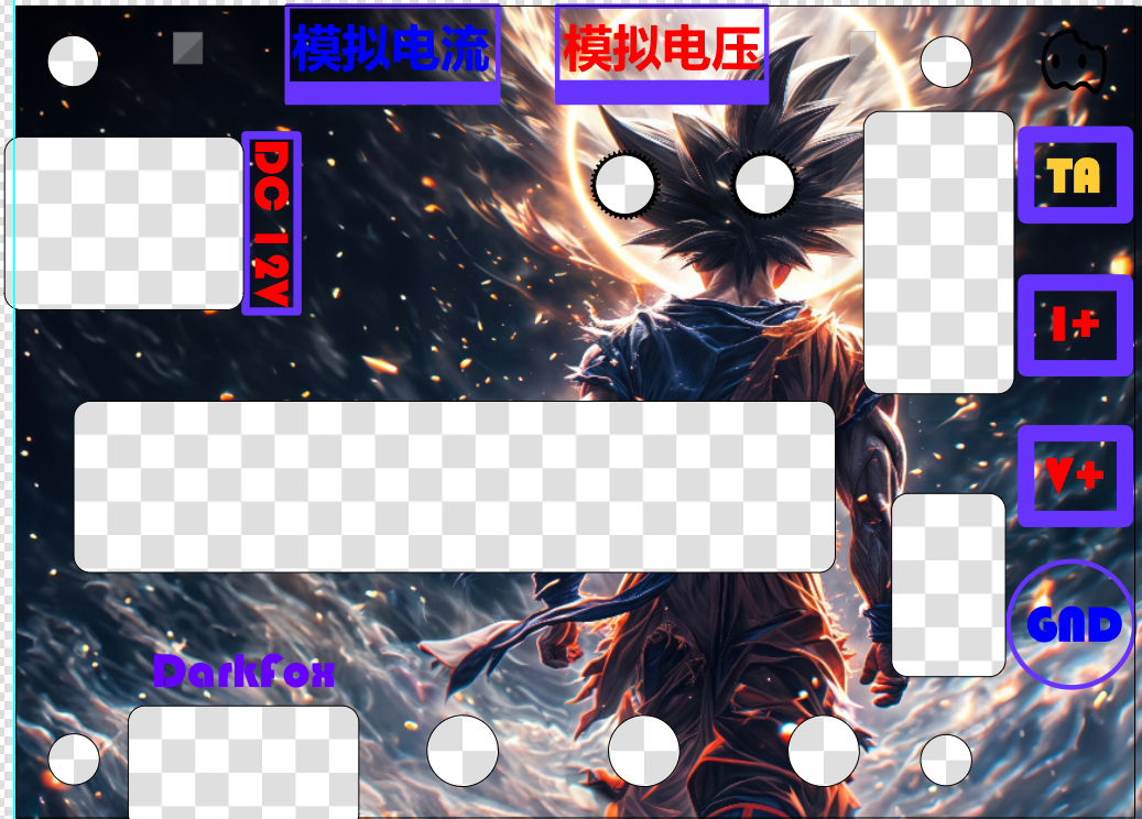
the panel design was designed
because it was my first time using JLCPCB's panel service, so there were some things I didn't understand, and therefore I designed three different panels;
the Miku and
Hatsune Miku versions were designed because I didn't quite understand the impact of the transparency parameter, so at 80.80% transparency, you need to be very close to see the display effect clearly, so it is recommended to use a more transparent or cutout panel for easier observation of the digital tube;

The WuKong version of the
Wukong version has a hollowed-out central display area. Unfortunately, I couldn't find Black Myth materials at the time, so I used Dragon Ball materials instead (not for commercial use). This version was to test the dark effect of LCSC panel printing;
Vaporwave <<<
Vaporwave style theme; the dark tone makes the warm-colored charact


 京公网安备 11010802033920号

 SX63M12A5F7511


