is likely the last version of the 2.x series.
Version 2.0 is here.
Version 2.3 is mainly a redesign of version 2.0, merging the three PCBs into one and modifying the appearance to reduce assembly complexity.
If you find it troublesome to do it yourself or don't know how to solder, you can purchase it directly here. Quantities are limited, while supplies last. Workshop
You are free to: Share — reproduce, distribute, adapt, modify, transform, or create based on this work
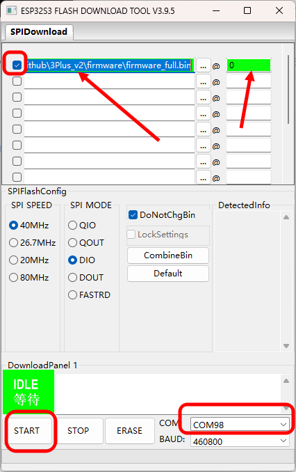
in any form or medium. As long as you comply with the terms of the license agreement, the licensor cannot revoke these rights. However, you must comply with the following conditions: Attribution — you must give appropriate attribution, provide a link to this license agreement, and indicate whether modifications were made (to the original work). You may use any reasonable means of attribution, but you may not in any way imply that the licensor endorses you or your use. Non-commercial use — You may not use this work for any commercial purpose. Share alike — If you remix, transform, or build upon this work, you must distribute your contributions under the same license as the original license. No additional restrictions — You may not use legal terms or technical measures to restrict others from doing what is permitted under the license. [Make] You can make your own based on my design. [Give] You can give away keyboards based on my design to your relatives and friends for free. [Sell] If you wish to sell this work or derivative works based on this work, please contact me in advance. Hardware ESP32-S3 NS4168 LSM6DS3TR-C 0.85-inch color screen, 128x128 resolution mechanical switches + switch base USB Type-C colorful LED lithium battery charging management firmware source code is developed in Python. First, install the bootloader firmware: Use the flash download tool to burn combined_tinyuf2_0.18.2.bin to address 0 of the board. Then copy firmware_magiclick_v2.3_9.1.1_0804.uf2 to the generated USB drive. The main tool used is Espressif's flash download tool. Install it as shown in the image below. Before powering on, hold down the knob and then power on. You will hear a sound from Device Manager indicating that the COM port has been detected. Release the knob and open the tool. Set it as shown in the image below. Note the red box in the upper left corner of the image below; it must be selected for successful burning. The COM port can be selected based on the specific port in Device Manager. The software code can be found in the DOC. Besides the BOM exported from the PCB, the following accessories are also required : countersunk self-tapping screws (M1.7*10, 4 pieces); acrylic panel (can be ordered directly from the LCSC online store using the attachment at the end of this document); 0916 cavity speaker ( 0.85 inch, long bar connector, 12-pin) ; 3D printed shell (refer to the lithium battery section 602025 in the DOC) . Note: Do not buy the wrong screen; please select according to the image. Different screens may cause display problems. For detailed DOC instructions, please refer to this document > [Click Here]
[Direct Order from LCSC Panels] Transparent Acrylic 1.0mm_Bottom Printing_v2.3.epanm
Used for the logistics handling track in the 2025 Industrial Tour, the main controller is Skystar STM32F407VET6. This expansion board can drive stepper motors, communicate via OpenMV, use Bluetooth for wireless communication, display via serial port, debug with buttons and an OLED screen, and learn servo control.
Video Link:
[Bilibili Video - Function Demonstration and Introduction] [SkyStar Expansion Board] https://www.bilibili.com/video/BV1GZskehEo7/?share_source=copy_web&vd_source=313763c4cf8391e7e2d0b4c06a66f331
Project Introduction
This expansion board is designed for the logistics handling track of the 2025 Industrial Training Competition. The main controller is SkyStar STM32F407VET6. This expansion board can drive stepper motors, communicate via OpenMV, use Bluetooth wireless communication, display via serial port, debug with buttons and OLED screen, and learn servo control.
Project Functions
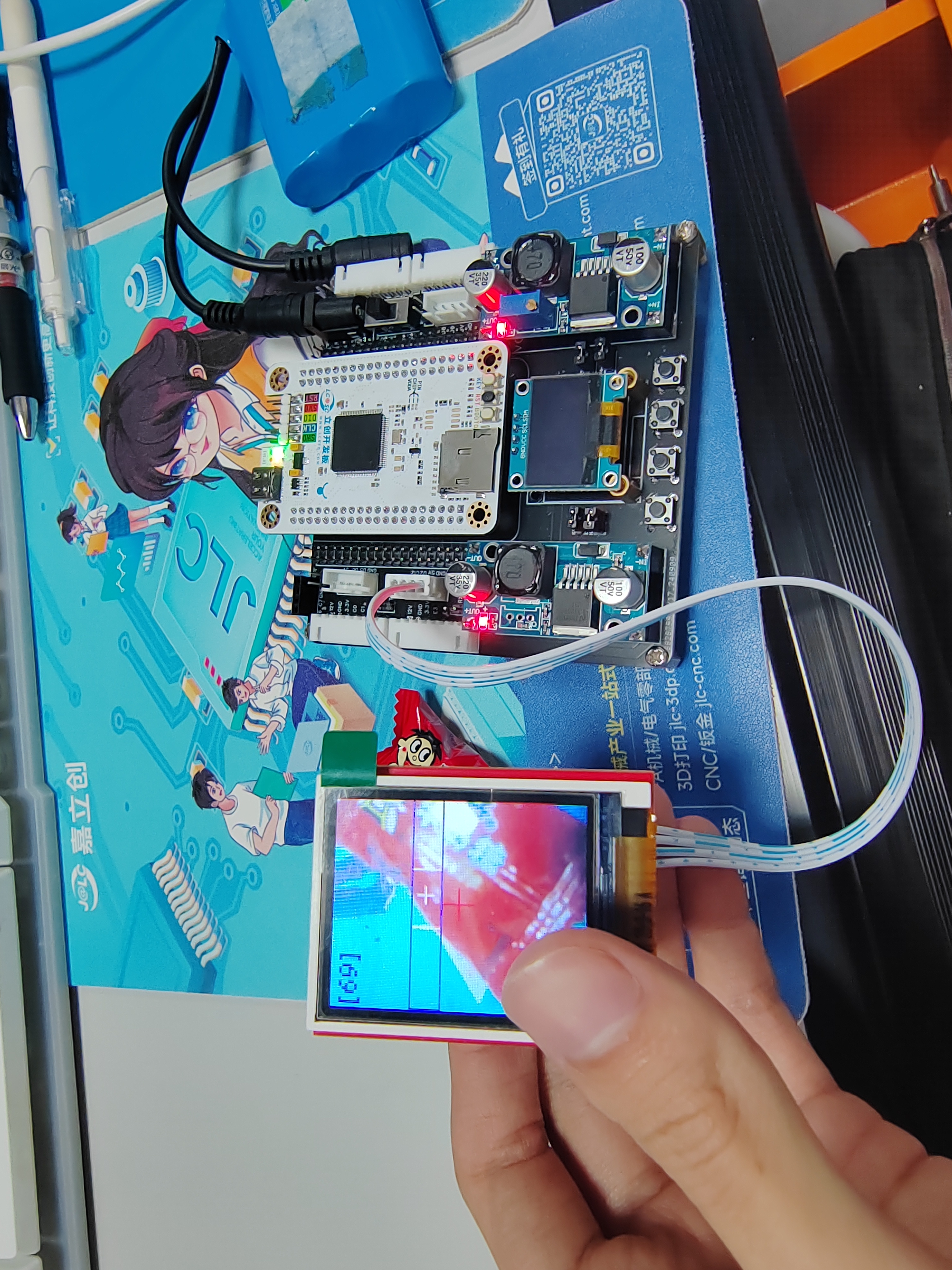
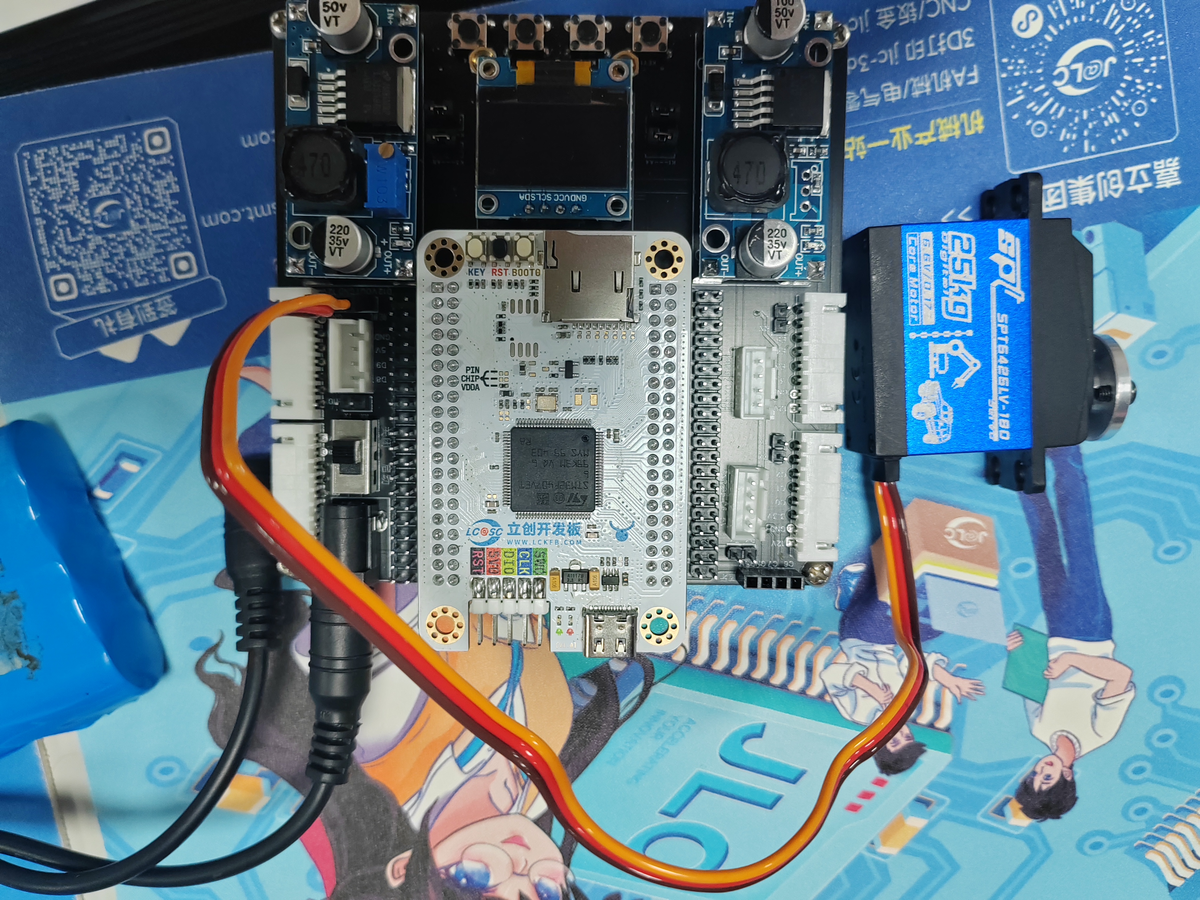
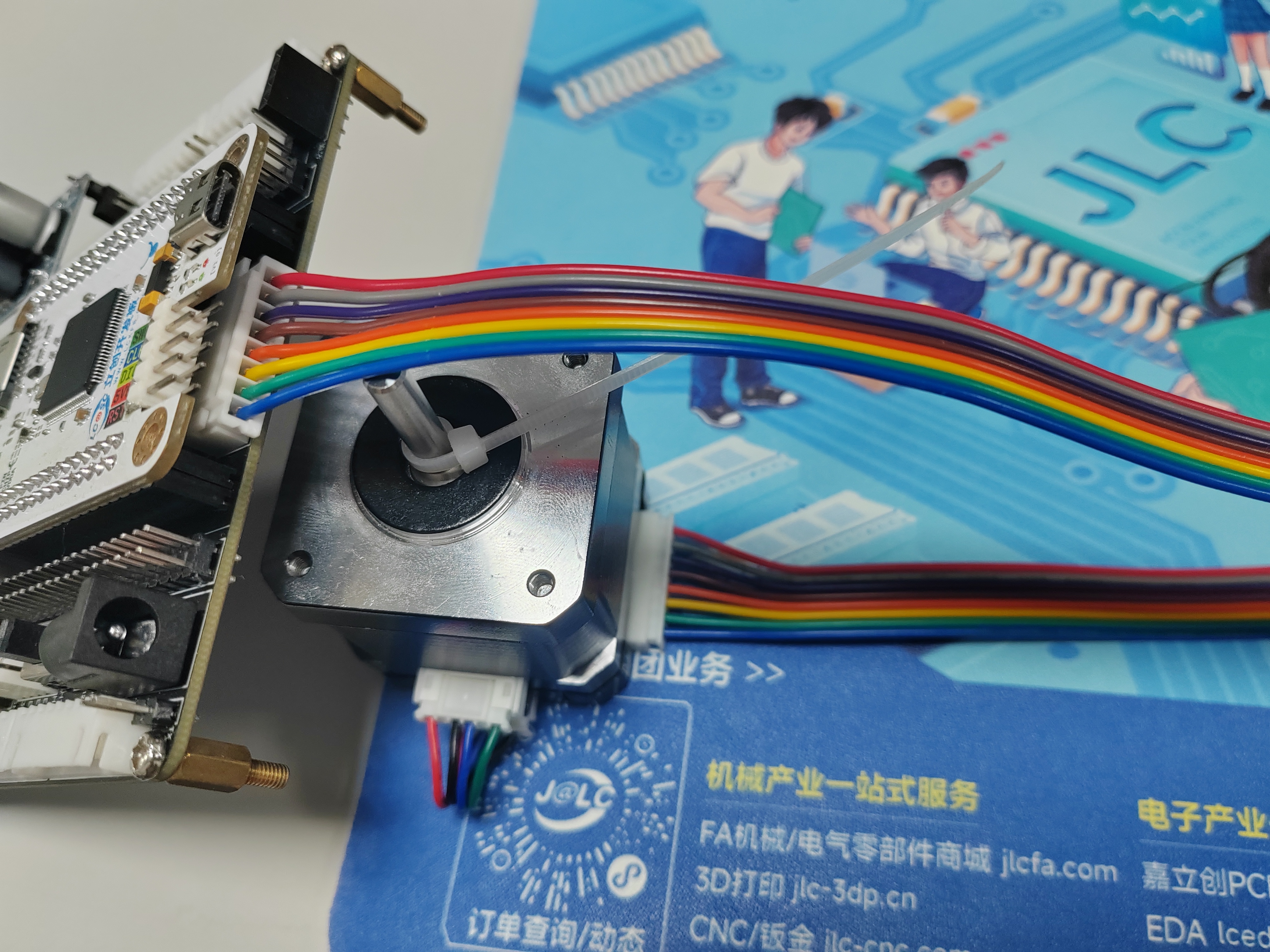
This project is an expansion learning board designed based on the SkyStar STM32F407VET6 development board of LCSC for preparing for the logistics handling track of the Industrial Training Competition. There are two 8P terminals on each side of the board that can be connected to stepper motors (Taobao Zhang Datou stepper motors) as wheel drive motors for the training vehicle. There is also a motor interface at the front that can be used to connect the sliding rail lifting motor. There is one servo interface for cargo gripping. There are two OpenMV interfaces for serial communication with cameras; one camera identifies and locates the cargo, and the other is used to recognize QR codes to obtain the handling sequence list. There is one serial screen interface for displaying the acquired handling information. Four buttons are used for parameter adjustment, and an OLED screen displays data interaction.
PCB Design Description:
This project consists of four main parts: power supply, main control circuit, peripheral interface circuit, and debugging module.
Example Figure 1 – Main Control Circuit:

All I/O pins are additionally brought out for easy subsequent development and debugging.
Example Figure 2 – Peripheral Interface Circuit:

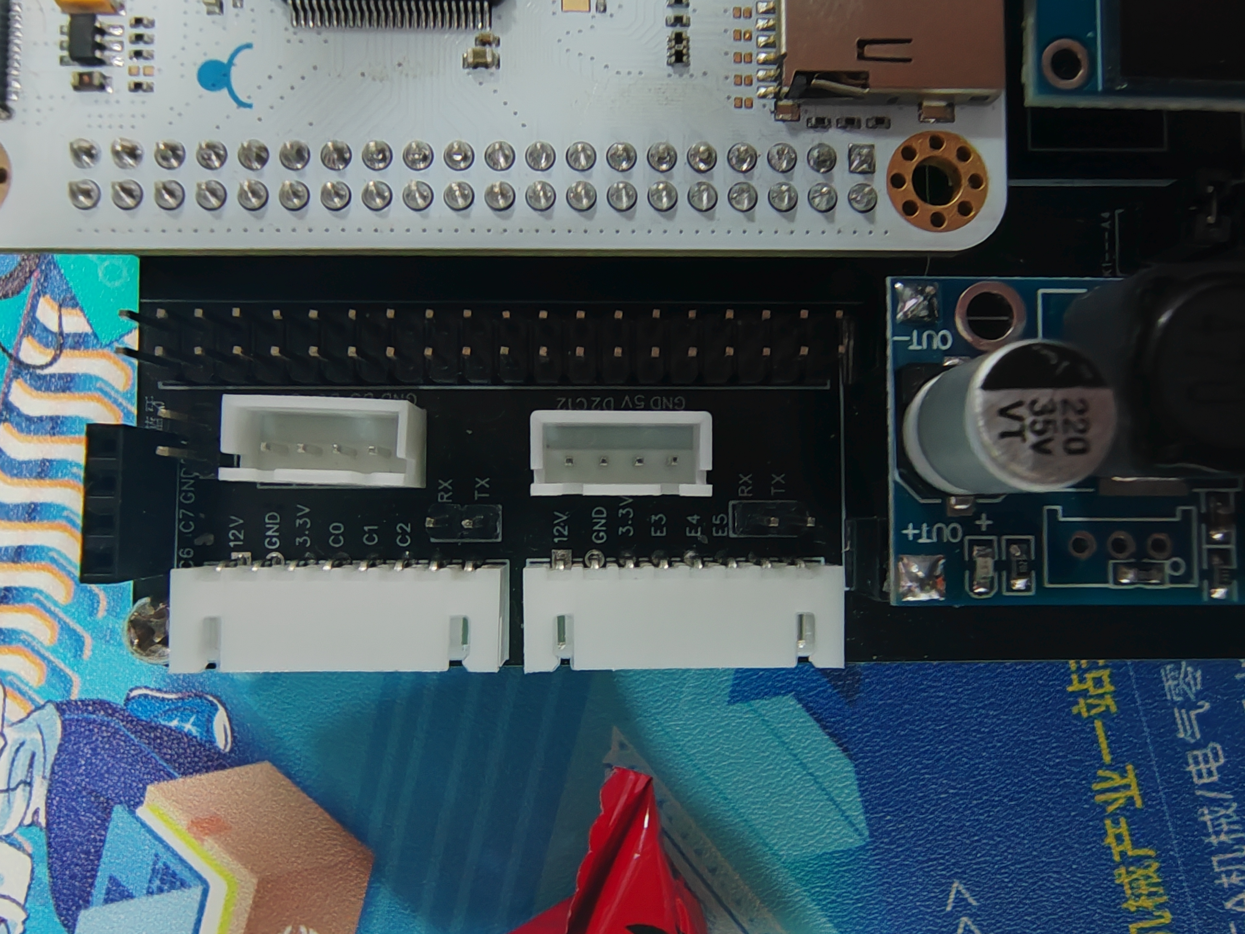
Each stepper motor can communicate with the main control via serial communication. Here, I have brought out the stepper motor communication interface and one serial port of the microcontroller. If serial communication is needed to control the motor, jumper caps can be used for connection. If serial communication is not needed, the pins can be used for other purposes.
Example Figure 3 – Debugging Module Circuit:
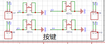
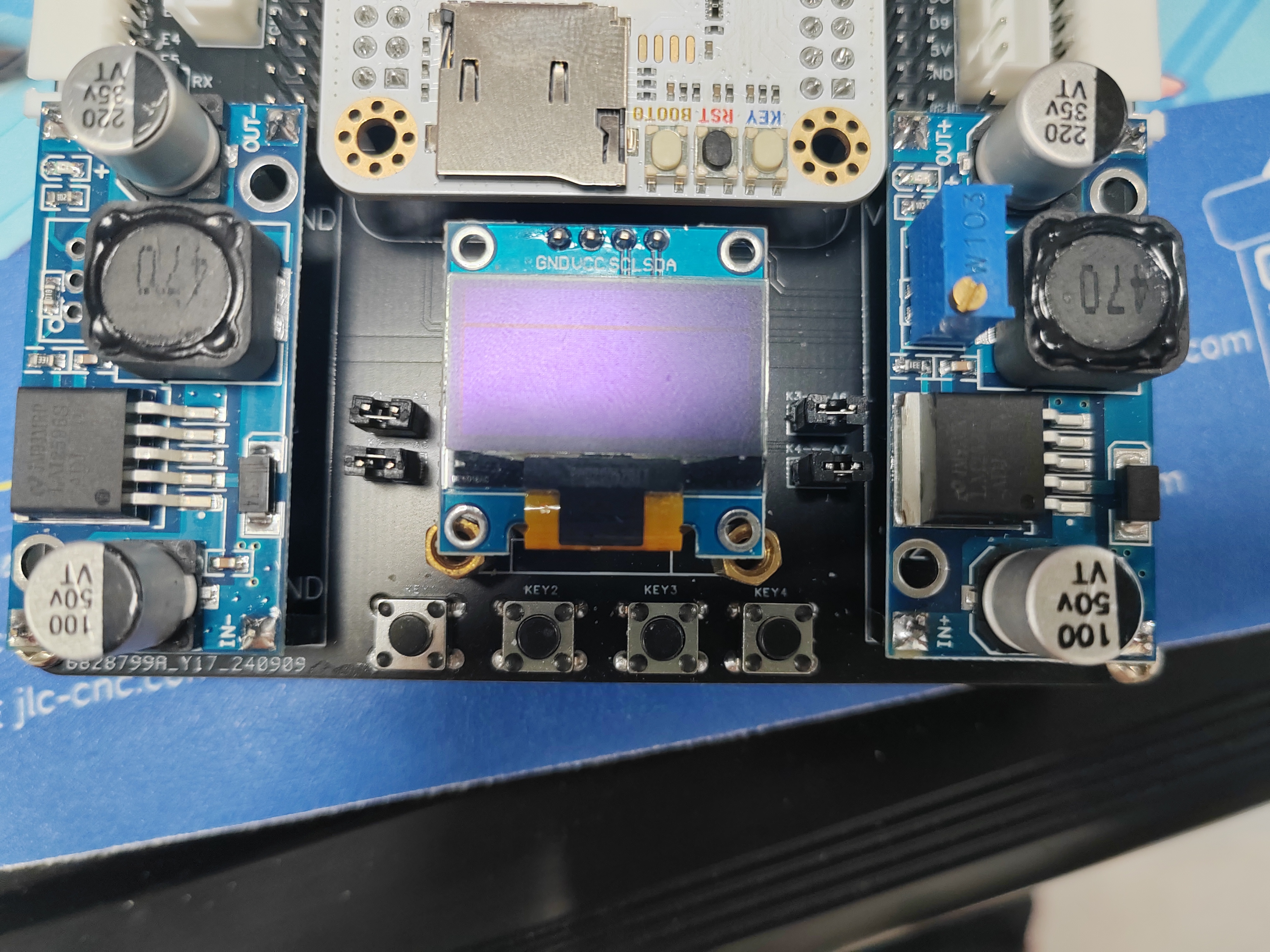
The button interface and the corresponding microcontroller I/O port are brought out separately. If button debugging is needed, jumper caps can be used for connection, or other purposes can be used.
Example Figure 4 -- Power Module Circuit:
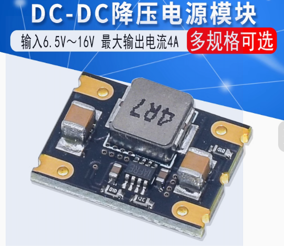
Uses an LM2596 voltage regulator module. One fixed 5V output powers the microcontroller, camera, serial port screen, and Bluetooth; one adjustable output powers the servo motor. Two voltage regulator modules are used to prevent the servo motor power supply circuit from affecting the power supply to the microcontroller and other modules.

Software code includes:
one code for communication with OpenMV, enabling camera line tracking; the camera returns the midpoint coordinates of the line.
One stepper motor drive test code.

Important material:
The motor was purchased from Taobao (Zhang Datou stepper motor).
Assembly instructions:
Bluetooth module assembly,

servo motor module assembly,
stepper motor assembly,
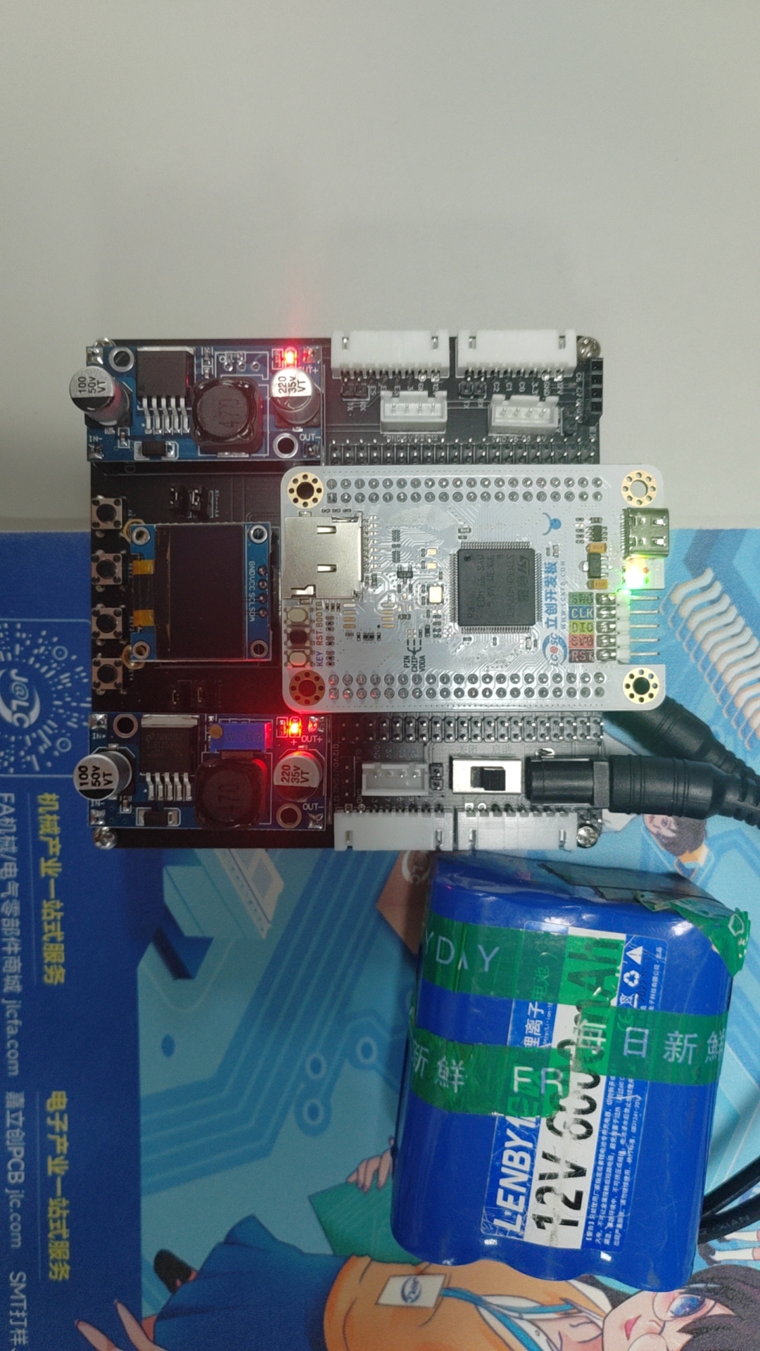
power supply battery (12V lithium battery pack).

[Image of the actual product]
STM32F407_Project----Stepper.zip
STM32F407_Project----openmv.zip
034815ce578b2e80498387381a3e97c7.mp4
PDF_Smart Car--Based on SkyStar STM32.zip
Altium Smart Car - Based on SkyStar STM32.zip
PADS Smart Car - Based on Skystar STM32.zip
BOM_Smart Car--Based on Skystar STM32.xlsx
91613
Intelligent access control system
A smart access control system based on the STM32F103C8T6 microcontroller supports RFID card, fingerprint, and password unlocking (reading and writing to internal flash memory is retained even after power loss). The ASRPRO Tianwen development board is responsible for broadcasting and voice recognition.
Components:
STM32F103C8T6 minimum system board
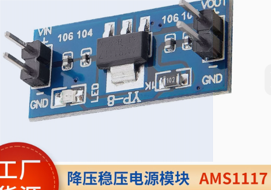
, 12V to 5V step-down module,
5V to 3.3V module
, OLED 0.96-inch four-pin
RC552 module,
AS608 fingerprint module,
16x6*5*5 tactile switch matrix keyboard
, buzzer module,
130 DC motor ,
ASRPRO development board with microphone (not the core board),
DC005 female connector (for lithium battery),
SS-12D10L5 toggle switch,
one 1k through-hole and surface mount resistor, and LEDs (0805 surface mount package, used for lighting simulation and power indicator).
Functions:
Access control:
fingerprint, RFID card support login, registration, and deletion modes.
Passwords only support registration and login.
Matrix keyboard: * key for login, # key for registration password, = key for confirmation password, other keys can be freely entered. Passwords support a maximum of 6 digits.
Display and feedback:
The OLED displays the current mode and on/off status in real time, and indicates success or failure.
A buzzer will sound a long response after the access control unlocks; a buzzer will sound a rapid error if various errors occur (login failure, registration while not logged in, deletion).
ASRPRO:
Customize voice recognition prompts using the Tianwen Block graphical programming software. These prompts control the switching of ID card, fingerprint, and password lock modes. After opening the door, lights and motors can be turned on or off via voice. After voice recognition, corresponding commands are sent to the STM32 via serial port. The serial port callback function switches modes and statuses according to the commands. (

Tianwen Block settings ↑)
Door.rar
PDF_Smart Access Control System.zip
Altium Smart Access Control System.zip
PADS Smart Access Control System.zip
91614
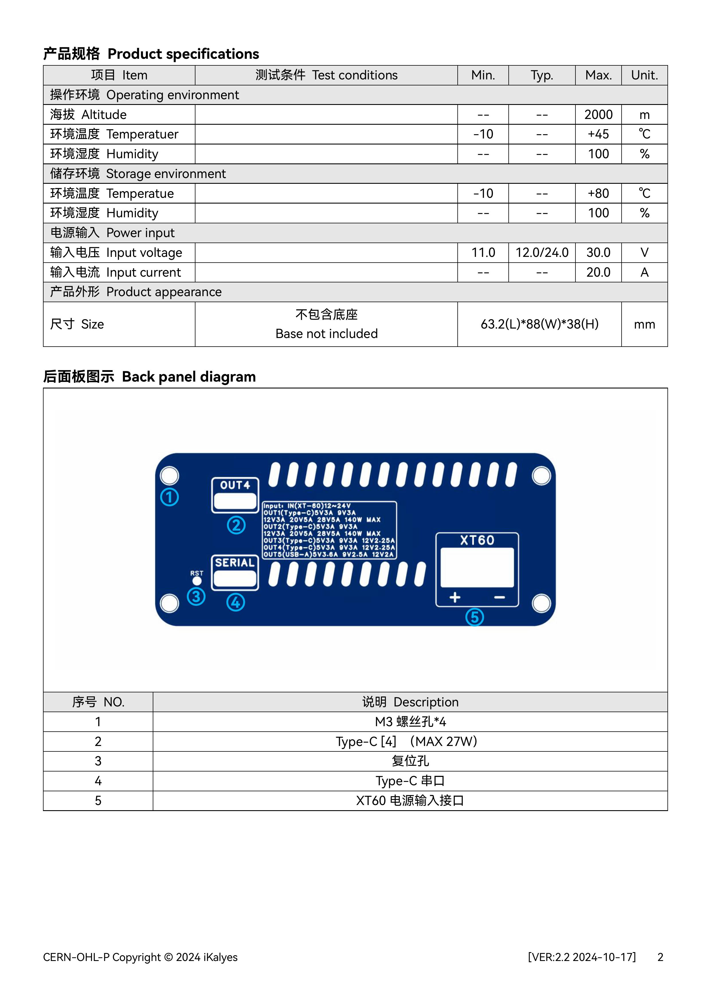
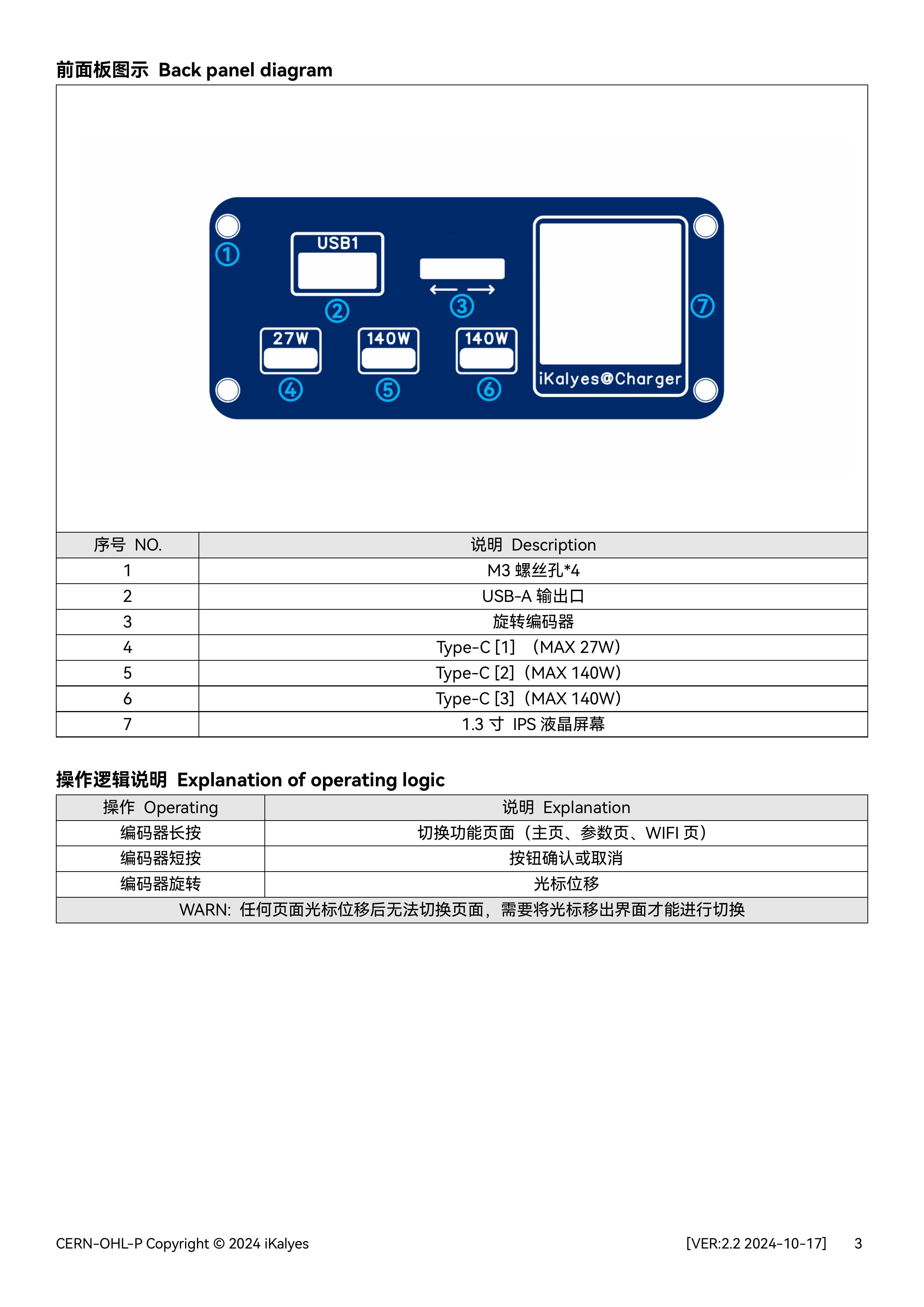
Multi-protocol desktop charging station 2.2
This is a desktop charging station (version 2.2) with four USB-C ports and one USB-A port, featuring voltage, current, and power monitoring, and is based on the Oringin open-source IoT multi-protocol power supply.
Firmware2.0.zip
Desktop Charging Station Source2.0 Code.zip
Multi-protocol desktop charging station 2.0 model.step
Multi-protocol Desktop Charging Station 2.2 (User Manual).pdf
PDF_Multi-protocol Desktop Charging Station.zip
Altium Multiprotocol Desktop Charging Station.zip
PADS Multi-Protocol Desktop Charging Station.zip
BOM_Multi-protocol Desktop Charging Station.xlsx
91615
APM/PX4 CAN Expansion Module
APM, CAN module
Project Introduction:
This module is an expansion module for the CAN bus interface of the APM flight controller.
Project Functionality:
When the flight controller's interfaces are insufficient, the CAN interface of this module can be connected to the flight controller's CAN interface. The wiring of this module is the same as the wiring on the flight controller. Functionality can be enabled on the flight controller.
Project Parameters:
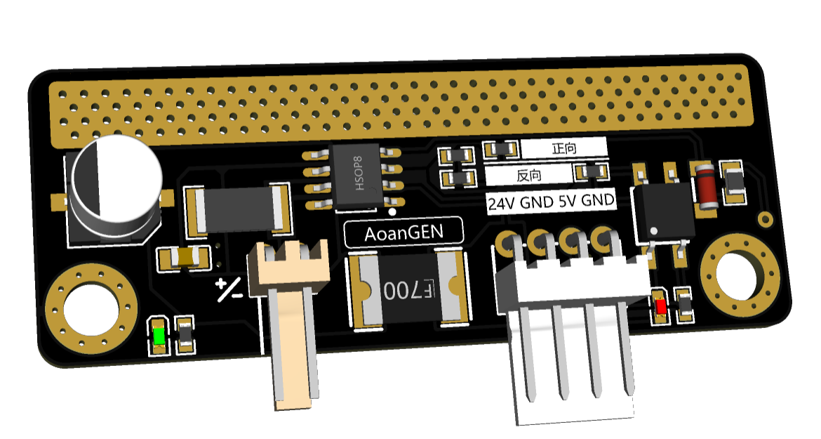
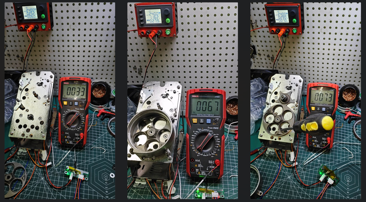
It can connect to a buzzer, 4 PWM outputs, an LED strip, three serial ports, two I2C ports, one SPI port, C_R connects to analog current, C_T connects to analog voltage, C-R2 is the current of the second battery if there are two batteries, BAT2 is the voltage of the second battery
...
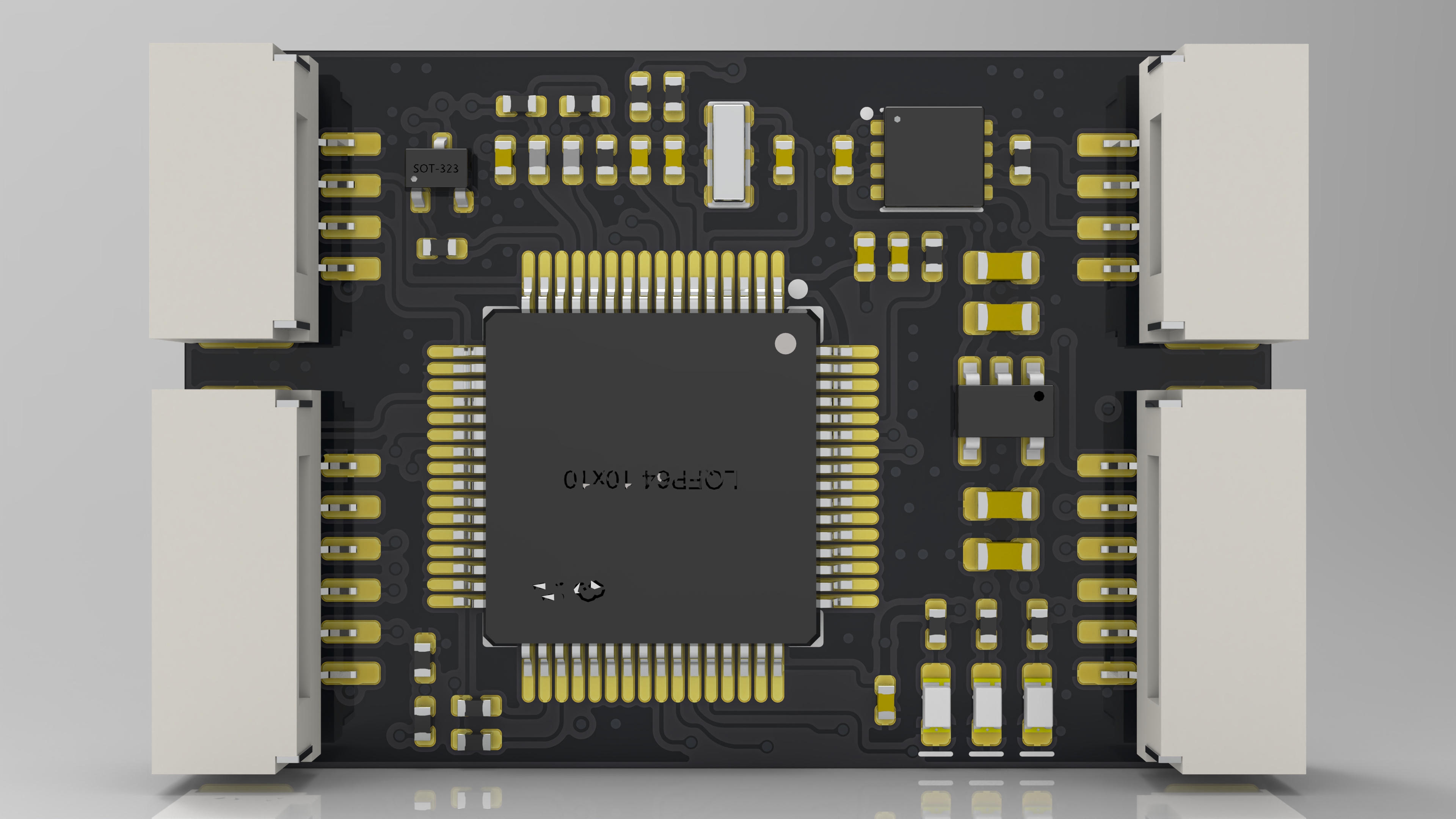
Rendering Images,

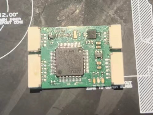
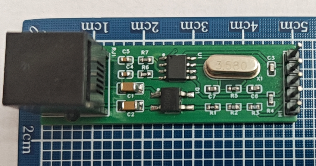
Physical Images,
Wiring Diagram

AP_Periph_with_bl.hex
PDF_APM-PX4 CAN Extension Module.zip
Altium_APM_PX4 CAN Extension Module.zip
PADS_APM_PX4 CAN Extension Module.zip
BOM_APM_PX4 CAN Extension Module.xlsx
91616
electronic


 It
It 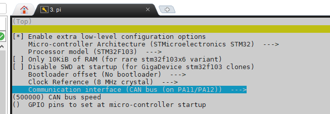 Select the "Communication interface" column according to your needs (the figure shows CAN communication; when selecting USB, the pins are also selected as PA11/PA12). The CAN rate must be consistent with the host computer settings. When using USB, the USB baud rate in printer.cfg remains unchanged by default.
  When using CAN connection, connect the motherboard power supply jumper cap shown in the diagram. When using USB connection, disconnect the jumper and power the core board via USB.
 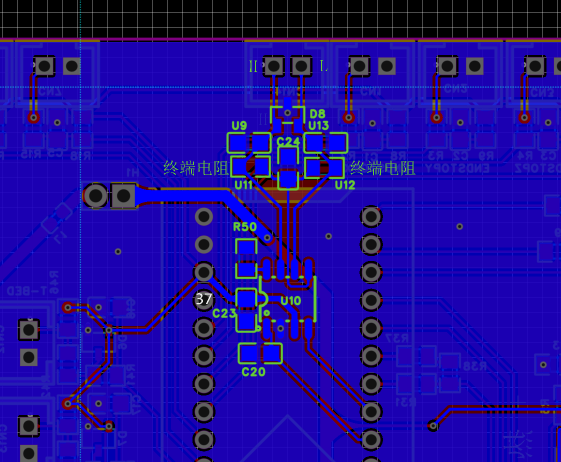 If a CAN transceiver is used, the terminating resistors U11 and U12 need to be selected according to the CAN bus connection. This design uses split terminating resistors, selecting two 60Ω or 1.3kΩ resistors (similar values are acceptable, such as 62Ω and 1.37kΩ), so that after the CAN bus connection is completed, the resistance between the H and L sides of the bus should be around 60Ω when measured with a multimeter. Resistor R50 is used to set the transceiver to work in slope mode, reducing speed and interference. If not needed, it can be removed and directly shorted to ground. Filter capacitors C20, U9, and U13 may need to be selected with a smaller value or removed depending on the communication speed.
  ----------------------------------------------------------------------------------------------------------------------------
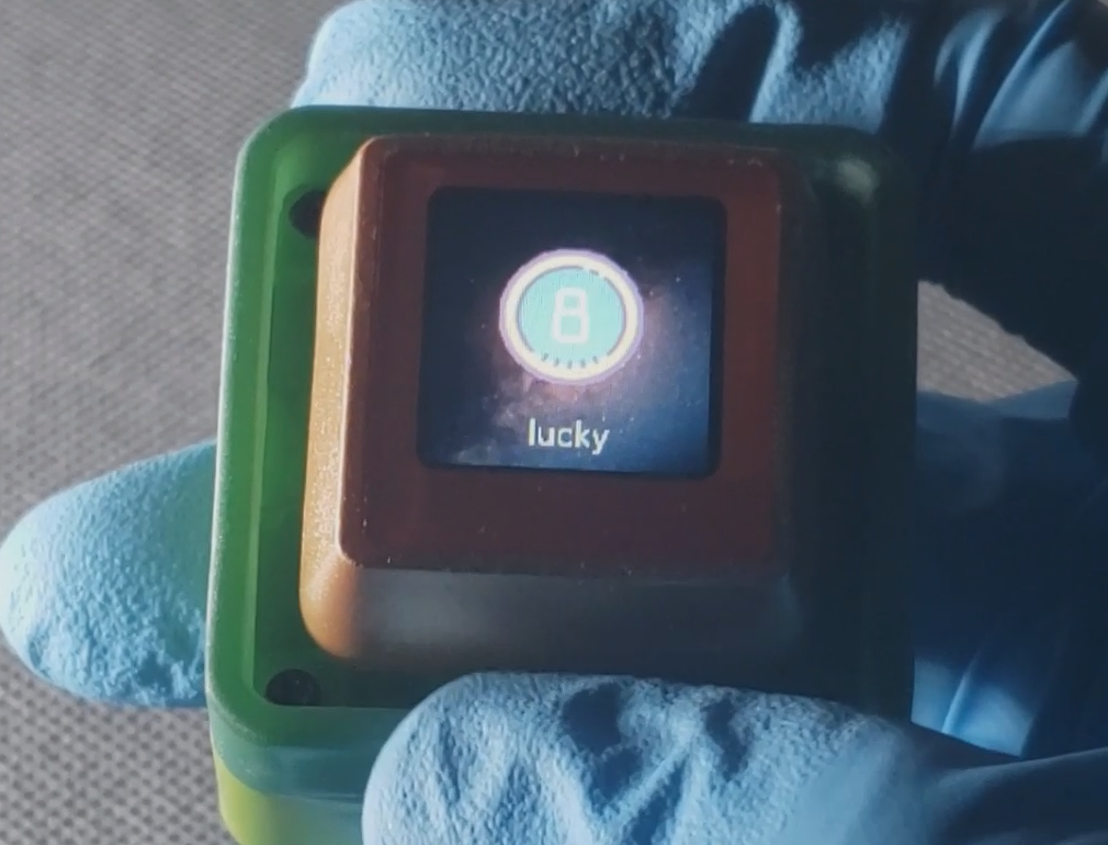
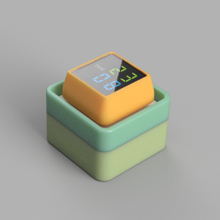 MagiClick Magic Button 2.3
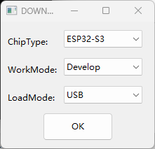


 If you have any questions, please join our discussion groups: 754881030 (original author's group) 790715767 (my group)


 京公网安备 11010802033920号

 516CEB000398AAG


