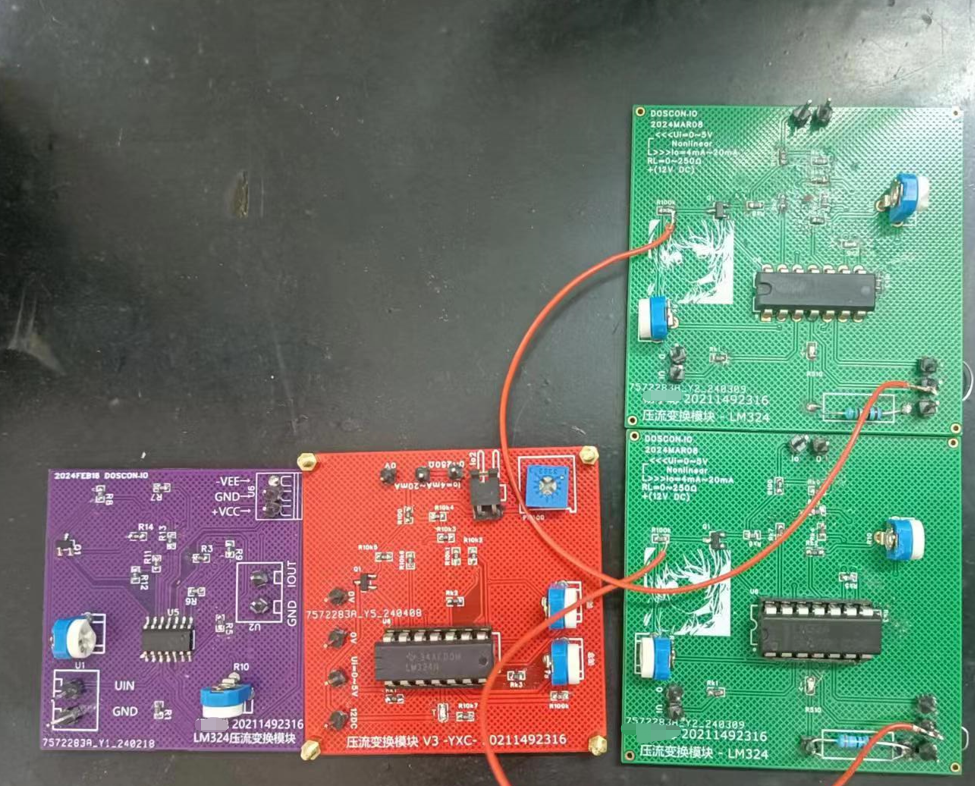
LM324 voltage-to-current converter (non-Howland solution)
12V-DC power supply
, input 0V~12V,
adjustable output 0mA ~ 20mA, corresponding to loads 0Ω~270Ω,
third edition.

PDF_LM324 Voltage-to-Current Converter.zip
Altium_LM324 voltage-current converter.zip
PADS_LM324 voltage-current converter.zip
BOM_LM324 Voltage-to-Current Converter.xlsx
95262
The Tianwen ASRPRO offline voice module is connected to Phone Assistant using ESP8266.
The board includes an ASRPro, an ESP8266, a temperature and humidity sensor (but in actual testing, the temperature display was found to be abnormal, so it is recommended not to install it), one infrared receiver, and two infrared transmitters, using the same I/O as the infrared companion. My example program is actually a modified version of the infrared companion.
1. Simple block diagram

. 2. Its name
happens to be all black, so I call it "Little Black."
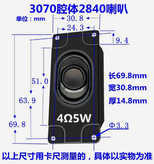
3. The wiring for assembling the speaker inside is soldered like this. Opening the cover too much risks breaking it.

The speaker is directly snapped in. I bought two types of speakers; one was the wrong size .

The speaker positioning and hole size were designed according to this size.
4. Due to video size limitations, the complete video can be viewed on Bilibili.
It also explains the burning timing when not using the official downloaded circuit: https://www.bilibili.com/video/BV1GF4m1N7by
3D Shell STL File.rar
ASRPRO Tianwen Source Code.rar
esp8266's esphome code.rar
PDF_Tianwen ASRPRO Offline Voice Module Connected to Honeyassistant using ESP8266.zip
Altium_Tianwen ASRPRO offline voice module connected to Honeyassistant using ESP8266.zip
PADS_Tianwen ASRPRO offline voice module connects to Honeyassistant using ESP8266.zip
BOM_Tianwen ASRPRO offline voice module connected to Honeyassistant using ESP8266.xlsx
95267
Liangshan School Cart
Based on Liangshanpai intelligent car
This project uses the GD32F470ZGT6 as the main control chip, which can realize functions such as infrared tracking, servo ultrasonic ranging and following, Bluetooth remote control, wireless control, light tracking, temperature and humidity detection, CAN communication, and AD sampling. It's essentially expanded into a development board in the form of a smart car, facilitating the learning and use of related peripherals of this chip (common peripherals such as UART, IIC, SPI, and CAN). 1. Power Supply Section: This design considers both functionality and cost, so the appearance is not very aesthetically pleasing; I cut off the rear of the car (oops... hence the battery holder is partially unsupported). The power supply is sourced locally. The company's products commonly use two types of batteries: 6V and 3.6V, which are readily available. The servo motor and N20 motor can both operate at 6V, while the Liangshanpai development board requires a 5V power supply. The 6V supply can be met by stepping down the voltage with an LDO, and the small voltage drop results in much lower power consumption. Here, the LM39100S-5.0 LDO is used. It should be noted that the smaller the voltage drop of the LDO, the better, as this reduces the power wasted in the LDO. Of course, the voltage drop cannot be less than the chip's minimum voltage drop (as shown in the figure, a voltage drop of 630mV can provide 1A of current, which means it can provide 1A of current for the car, excluding the servo motor and N20 motor). The main power consumption of the car includes the MCU (generally less than 250mA), Bluetooth module (150mA), CAN module (50mA), temperature and humidity module (50mA), wireless module (100mA), infrared module (100mA), etc.
WeChat_20240121220027.mp4
WeChat_20240121220042.mp4
WeChat image_20240229140527.jpg
WeChat image_20240229140537.jpg
SCH_SCH_Car_2024-04-09.pdf
Gerber_PCB1_2024-04-12.zip
PDF_Liangshanpai Cart.zip
Altium_Liangshanpai Cart.zip
PADS_Liangshanpai Cart.zip
BOM_Liangshanpai Car.xlsx
95268
4x4 keyboard based on 38-bit decoding
4x4 keyboard based on 38-bit decoding
A 4x4 keyboard based on 38-bit decoding
: https://gitee.com/akatople/4-4-jian-pan
BOM_Based on 38-bit decoding 4_4 keyboard.xlsx
95269
I recommend open-source campus cards and black/white cards.
Transform your campus card into an anime style.
Simply remove the chip from the card and solder it on. Alternatively, you can buy a blank card, write the chip into it, and then remove the chip and solder it on. The LEDs and resistors used are 8085 series, and the resistors are 100 ohms. These are easily found on Taobao.
If you have a coupon, it's free.
You can simply remove the campus card chip and solder it on, or you can buy a blank card, write the chip into it, and then remove the chip and solder it on. The LEDs and resistors used are 8085 standard, and the resistors are 100 ohms; these are easily found on Taobao.
Video_1712903966940.mp4
PDF_Campus Card Open Source I Recommend Black and White.zip
Altium_Campus Card Open Source I Recommend Black and White.zip
PADS_Campus Card Open Source - I Recommend Black and White.zip
BOM_Campus Card Open Source I Recommend Black and White.xlsx
95272
PowerBoard
The power conversion module is powered by a 5V input via Type-C and can output five voltage levels: 5V, 3.3V, 2.5V, 1.8V, and 1.2V.
The power board converts 5V power to multiple voltage levels.
PDF_PowerBoard.zip
Altium_PowerBoard.zip
PADS_PowerBoard.zip
BOM_PowerBoard.xlsx
95273
Have you gotten MyGo hooked? (MyGo-themed light display)
A very ordinary, unremarkable light and shadow display at the Mygo kitchen!
(Aine is so cute!)
Referring to the schematic diagram of the following project, I re-optimized the position and labels of the touch buttons! https://oshwhub.com/gxts/deng-guang-hua-_-cai-se-si-yin-_h
I'm quite satisfied with how it works, aren't I? (Hehe)
1. The board might be too thick; try 1.2cm thickness
. 2. The light source distribution should be more even, otherwise it's easy to get a dark face (just kidding).
PDF_Have You Goen'd Become Addicted? (MyGo-Themed Light and Light Art).zip
Altium_Have you gotten MyGo on it? (MyGo-themed light painting).zip
PADS_Have you gotten MyGo on it? (MyGo-themed light and shadow artwork).zip
BOM_Have you gotten MyGo hooked? (MyGo-themed light and shadow artwork).xlsx
95274
#Training Camp# GD32 Simple Oscilloscope
This project utilizes the GD32E230 microcontroller to implement the LCSC open-source simple oscilloscope project.
Design of a portable and simple oscilloscope based on GD32E230C8T6.
A digital oscilloscope is an instrument used to display electrical signal waveforms. It mainly consists of analog front-end processing circuit, microcontroller circuit, power supply circuit, control circuit, trigger circuit, calibration circuit, etc.
Since this project is an introductory project for oscilloscopes, some core circuits were selected in the circuit design to help beginners better understand the principles and design methods of oscilloscopes. The main circuits include the following:
(1) Analog front-end processing circuit: responsible for processing the input detection analog signal and then sending it to the microcontroller for recognition. The specific circuits include AC/DC coupling selection circuit, voltage attenuation circuit, signal processing circuit, and frequency detection circuit, which is the core of the entire circuit.
(2) Power supply circuit: responsible for providing positive and negative power to the operational amplifier and system power supply, which is the basis for ensuring the normal operation of the circuit.
(3) Microcontroller circuit: provides the control core for the system and is responsible for the acquisition, processing, and output of input signals.
(4) Human-computer interaction circuit: used to control the functions of the oscilloscope, including buttons, knobs, LEDs, display screen, and other input/output interfaces, providing a foundation for the development of oscilloscope functions.
Measurement range: -80V — +250V
Data Learning and Downloads
GD32E230 Data: https://lceda001.feishu.cn/wiki/Tlp5wNmPii2oKekezjpcCeA7ndh
Open Source Oscilloscope Data: https://www.yuque.com/wldz/jlceda/dso
Program Data Download: https://gitee.com/chen11232/GD32E230-Oscilloscope
Bilibili Video Link: https://www.bilibili.com/video/BV1Ct421G7qi/?share_source=copy_web&vd_source=7d6b44d04710561a688ec20e7b994b95
Oscilloscope Materials and Preparation
1. Purchase the PCB according to the BOM or schematic diagram; other parts are described below.
2. The overall components include: PCB board + 1.8-inch screen + lithium battery + oscilloscope probe.
3. Oscilloscope Probe: Uses an SMB interface. This circuit is compatible with SMA interfaces; it can be replaced with an SMA interface if needed.
4. Lithium Battery: Uses a 3x3x0.9cm (1000mAh) battery, or a battery of the same size but with a larger capacity.
5. Screen: Uses a 1.8-inch TFT color screen with an ST7735 driver chip.
6. Housing: 3D printed plastic material (resin may be too hard to install).
7. Terminals: M3*9.5mm screw posts, M3*8 screws (used for 3D printed housing).
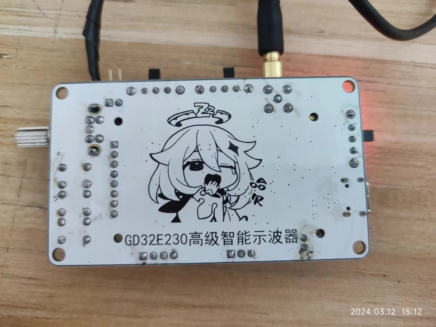
Top and

Bottom Physical Samples:
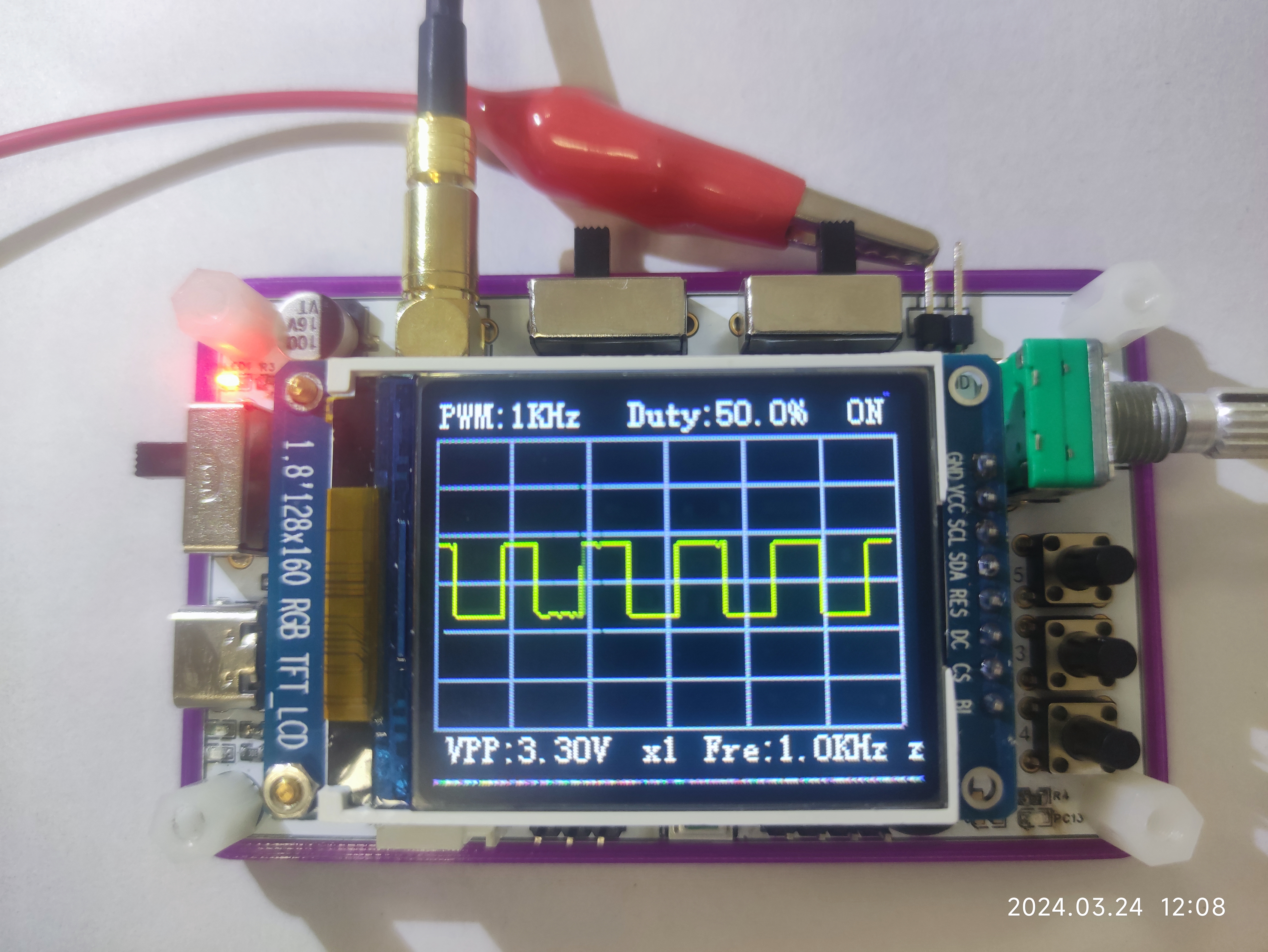
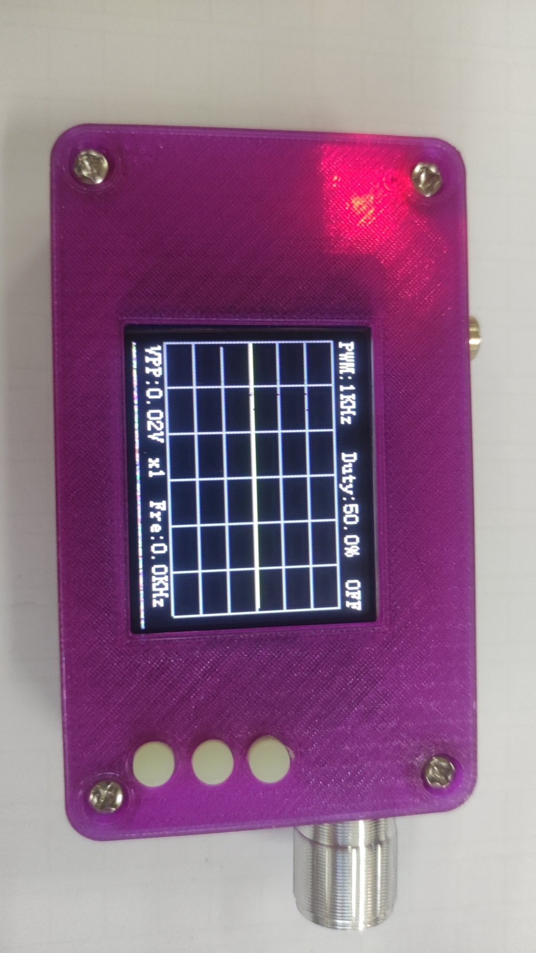
Waveform Input/Output Display:
Tested using an oscilloscope probe to measure the oscilloscope's built-in PWM output waveform.
Code Optimization:

3D Housing Modeling Effect:
Modeled using LCSC EDA Professional Edition + SolidWorks. The specific model file can be found in the project download section.


3D Housing Physical Sample Display
: The physical sample is printed. I originally wanted a more flashy color, but the effect is surprisingly poor. If you want to replicate it, you can consider changing to other colors. The size of this housing is fine.
Realistic Video 3D.mp4
3D Printing Order Version.zip
Oscilloscope.hex
Video Operation.mp4
PDF_#Training Camp#GD32 Simple Oscilloscope.zip
Altium_#Training Camp#GD32 Simple Oscilloscope.zip
PADS_#Training Camp#GD32 Simple Oscilloscope.zip
BOM_#Training Camp#GD32 Simple Oscilloscope.xlsx
95275
STM32F103C6T6 control board (imitating DJI's B board)
This is a replica of the DJI B board. There's a minor issue with the power module; hopefully, someone can optimize and improve it.

The board supports 8-channel PWM output, 2-channel CAN signal output, and D-Bus remote control communication. It also includes 4 I/O ports (with ADC sampling capability).
The power supply supports 5-35V input. The 5V motor and servo output ports
had been modified several times due to a persistent power module issue; after four consecutive board modifications, this version is barely usable, with improved heat dissipation.
PDF_STM32F103C6T6 Control Board (Imitation DJI B Board).zip
Altium_STM32F103C6T6 control board (imitating DJI b board).zip
PADS_STM32F103C6T6 control board (imitating DJI B board).zip
BOM_STM32F103C6T6 Control Board (Imitation of DJI B Board).xlsx
95276
electronic


 京公网安备 11010802033920号

 C052C229H1R5TA


