This open-source project is part of the CW32 Voltage and Current Meter Training Camp, and is a replication and simple extension of the example project "【LCSC Development Board】CW32 Voltage and Current Meter Training Camp". Based on the original reference circuit, it adds an integrated serial port (for user USART peripheral testing, ISP mode download testing, CH340C_batch number starting with 4 and the last 3
digits greater than B40_external-free automatic download circuit testing), external flash, RGB, etc. The purpose of this open-source project is to teach the relatively basic but important theoretical knowledge in electronic circuit measurement—the measurement of voltage and current. Voltage measurement aims to measure the potential or potential difference at various points in an electronic circuit. The potential difference between two points in a circuit is the energy that a unit charge can gain or lose in an electric field, usually measured in volts. Current measurement determines the characteristics of the current in a circuit by measuring the magnitude and direction of the current. The main method is to measure the voltage drop across a known current-sensing resistor and calculate the current using Ohm's law (I=U/R).
This project emphasizes both hardware and software. In hardware design, the following should be considered:
(1) Effective filtering of capacitors related to current flow, and the design and handling of high-current paths;
(2) The necessity of isolation between analog and digital grounds;
(3) The effect of Kelvin connection on common-mode noise suppression during measurement sampling;
(4) PCB passive heat dissipation design;
(5) Hardware installation compatibility;
(6) Hardware preset scalability.
In software design, the following should be considered:
(1) Establishment of the basic engineering SDK;
(2) Software system architecture;
(3) The difference between ADC error and ADC accuracy;
(4) Methods for sampling error correction and calibration.
I. Item
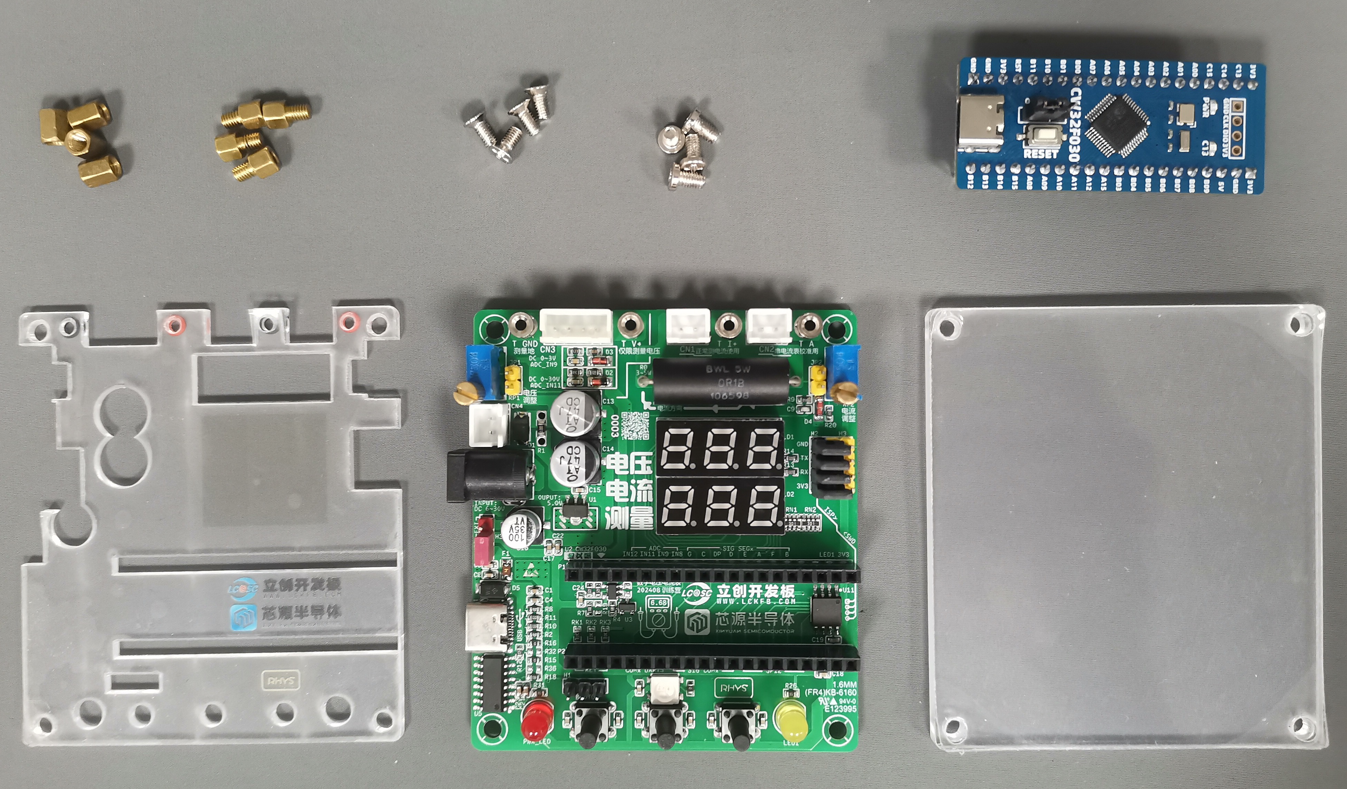
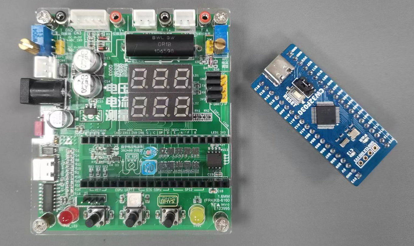
Description Quantity
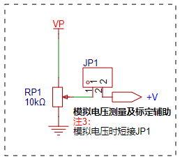
1 M3 countersunk screws 4 2 M3 flathead screws 4 3 M3 double-ended copper pillars 4 4 M3 single-ended copper pillars 4 5 LCSC CW32F030C8T6 development board 1 6 CW32 voltage and current meter expansion baseboard 1 7 Acrylic panel (top) 1 8 Acrylic panel (bottom) 1. Perform simple assembly according to the list to obtain the hardware foundation for debugging code. II. Hardware Design The CW32 hardware design can be divided into: (1) Digital tube display circuit; (2) Voltage measurement and analog voltage input circuit; (3) Current measurement and analog current input circuit; (4) USB-USART-BRIDGE circuit and ISP external automatic download circuit (including ESD) with CH340C as the important component; (5) Power supply circuit; (6) External FLASH circuit, button circuit, indicator circuit, etc. with W25Qxx as the important component. 2.1 Digital Tube Display Circuit This design uses the GPIO ports (in push-to-control mode) of the core MCU (CW32F030C8T6) for direct control, occupying 6 bit control ports and 8 segment control ports, supplying 14 GPIO ports. The corresponding mapping table is as follows: (Please note: For layout priority, the author has adjusted the hardware control ports. If you need to use the author's code, please modify the control port mapping, otherwise it may cause your hardware digital tube display to malfunction!!) Digital Tube Control Terminals CW32 GPIO DIG_1 PA08 DIG_2 PA11 DIG_3 PA12 DIG_4 PA15 DIG_5 PB03 DIG_6 PB04 SEG_A PA02 SEG_B PA00 SEG_C PA06 SEG_D PA04 SEG_E PA03 SEG_F PA01 SEG_G PA07 SEG_H /DP PA05 controls the high and low levels of the corresponding digit and segment terminals via GPIO to light up the LEDs at the corresponding positions. For a single digit of a digital tube, multiple segments can be lit simultaneously to form English letters or arrays; for digital tubes with different digits, the display interval can be controlled to perform scanning display (using afterglow to create a visual persistence effect), achieving the effect that multiple digital tubes can be displayed simultaneously to the naked eye. 2.2 Voltage Measurement and Analog Voltage Input Circuit The voltage measurement circuit example shows two circuits: 0 ~ 30V DC range and 0 ~ 3V DC range, and uses a separate ADC channel, which can be used with software to design automatic range switching. (1) The voltage input (+V) is divided by a 220kΩ and a 10kΩ resistor and acquired through the ADC_IN11 channel. The voltage input-output relationship is: V_ADC_IN11 = (+V) * 10K / (10K + 220K). When the input (+V) = 0 ~ 30 DCV, (V_ADC_IN11) = 0 ~ 1.3 DCV, which meets the condition of CW32F0xx using the internal 1.5V reference. This is the 0~30V DC range. (2) The voltage input (+V) is divided by a 10kΩ and a 10kΩ resistor and acquired through the ADC_IN9 channel. The voltage input-output relationship is: V_ADC_IN9 = (+V) * 10K / (10K + 10K). When the input (+V) = 0 ~ 3 DCV, (V_ADC_IN11) = 0 ~ 1.5 DCV, which meets the condition of CW32F0xx using the internal 1.5V reference. This is the 0~3V DC range. (3) Analysis of ineffective clamping protection

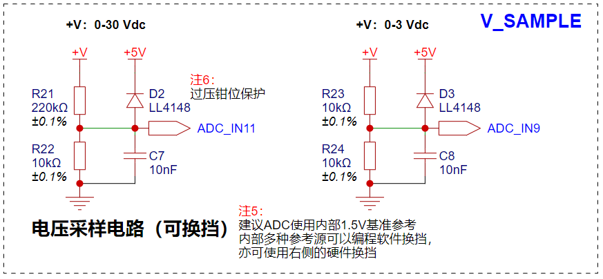
Because both voltage divider circuits are operating normally, there exists a situation where, when the (+V) voltage exceeds 6.6 DCV, for the 0~3V DC range, the voltage input on the ADC pin exceeds 3.3V. The CW32F0xx chip's pins do not have a voltage tolerance design exceeding 3.3V.
Reference: CW32F030_DataSheet_CN_V1.8, page 34.

The relevant limit parameters can be found on page 34 of the datasheet CN_V1.8. In the example and this project, we actually wanted to consider this situation and therefore designed overvoltage clamping protection, but it still has shortcomings. Readers who replicate this circuit should definitely consider this situation!
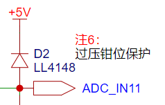
The author provides a possible solution:
Solution 1 : Maintain the
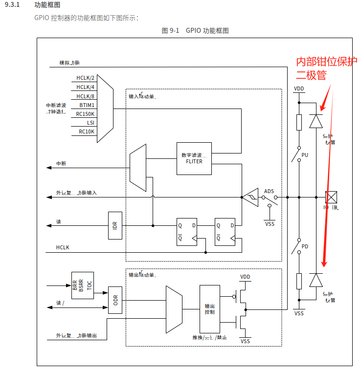
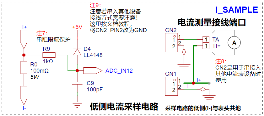
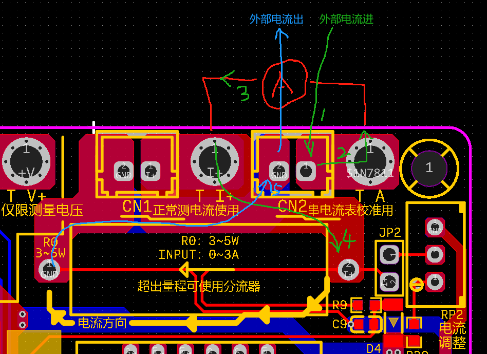
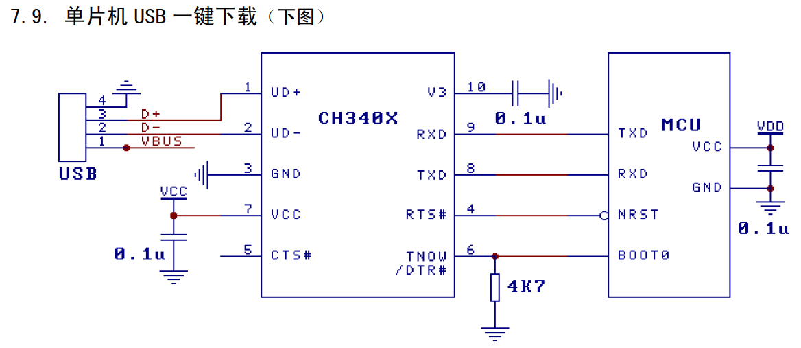
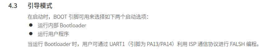
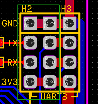
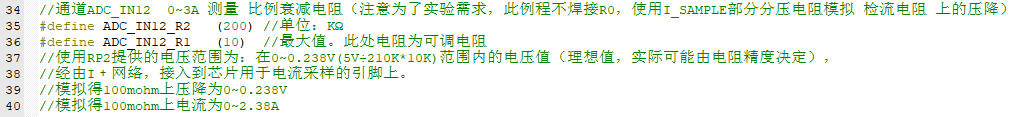
circuit as described in the author's circuit, clamping to +5V. However, the microcontroller actually operates at VDD = 3.3V. Therefore, the voltage divider resistors for the 0~3V range need to be modified, sacrificing the accuracy of automatic range switching to avoid the analog I/O port burning out when the (+V) input exceeds 6.6V. Using a ratio of (12k + 100k) ensures that when the input reaches a maximum of +30V, the voltage of V_ADC_IN9 is +30V * 12K / (12K + 100K) = 3.214V < VDD. Schottky diodes are used to clamp to +VDD. In fact, all GPIOs of the CW32F0xx have upper and lower clamps, so external clamp protection requires an extremely low on-state voltage drop; otherwise, the internal clamping diodes of the CW32F0xx will be used while the external ones are not! Reference: CW32x030_UserManual_CN_V2.5 Page 144 (4) Analog Voltage Input In the absence of an external input source, or when only the onboard voltage source is used, the analog voltage input can be used to test and calibrate the sampling results of the CW32F0xx internal ADC. This part of the circuit consists of a potentiometer and a jumper cap. The potentiometer is used to adjust the voltage divider ratio output (VP), so that an analog value can be given to the voltage measurement input (+V). With other higher precision voltmeters, ADC sampling tests, as well as related calibration and calibration work, can be performed. 2.3 Current Measurement and Analog Current Input Circuit The current measurement range of the project is 0 ~ 3A. The voltage difference caused by the current sensing resistor is generally not recommended to exceed 0.5V. The design uses a resistance value of 0.1Ω, which corresponds to a voltage drop of 0 ~ 0.3V and a maximum power consumption of 0.9W. Therefore, the package of the R0 current sensing resistor should be at least 1W. Here, a conservative design is adopted, using a 5W precision wire-wound resistor package. The difference between this design and the reference standard is that pin 2 of CN2 is grounded, so that the test circuit is grounded. When using it: (1) Calibration: CN2 is used alone in series with other ammeters. The specific connection method and current flow are shown in the figure below: CN2: External current I+>> Ammeter>> Onboard current sensing resistor>> GND (2) Normal measurement: CN1 is used alone. The specific connection method and current flow are shown in the figure below: CN1: External current I+>> Onboard current sensing resistor>> GND (3) Analog current input : When the analog current input part needs to be enabled, R0 (current sensing resistor) must be removed and JP2 (jump cap) must be connected. If R0 is soldered, the voltage divider will be coupled with the analog part, the voltage calculation formula will be changed, and the simulation effect will also be changed. Here, a 200K + 10K (adjustable) voltage divider (+5V) is used to simulate the voltage drop across the current sensing resistor when there is current input. Under these parameters, the output voltage to (I+) is 0 ~ 0.238V, and the simulated current is 0 ~ 2.38A. 2.4 USB-USART-BRIDGE Circuit and ISP Automatic Download Circuit : According to the latest version of the CH340 datasheet, specific batches of CH340C can be used directly, along with the hardware circuit settings, to build an ISP automatic download circuit without external components. Reference: CW32F030_DataSheet_CN_V1.8 8 pages. The CW32F0xx supports ISP downloading, therefore the following hardware circuit can be designed: It should be noted that the CH340C in the expansion board is not only used for testing ISP downloading, but also for communication with the CW32F0xx UART peripheral. Therefore, set up corresponding pin headers and place them in close proximity during PCB layout: When the CH340C is needed to communicate with the CW32F0xx UART peripheral, H2 is connected using 4 jumper caps by default; when the CH340C is needed to download programs to the CW32F0xx ISP, remove all jumper caps from H2 and connect H3 to the SW download port on the Diwenxing development board (actually, unlike STM32 microcontrollers, the CW32F0xx uses PA13/PA14 for both SWD and ISP program downloading). A major reason for designing the onboard USB-USART-BRIDGE circuit is that the USB port on the Diwenxing development board only provides power and lacks communication functionality. For beginners of CW32 microcontrollers, the absence of a debug printout makes software development and debugging inconvenient. Furthermore, the USB-TYPE-C port can directly power this project, allowing for program design and debugging even without an external power input. However, this raises a new problem: the two +5V outputs directly conflict, sometimes even causing backflow current into the 5V LDO chip! In practical applications, there are many ways to solve this, such as using a 10Ω resistor to isolate the two power supplies and reduce voltage drop; using a power switching chip; designing a circuit similar to an ideal diode using dual MOSFETs back-to-back with external resistors; or, as the author has done, using a jumper to select the power supply, which, while less intelligent, is economical and practical. 2.5 Power Supply Circuit Since the expansion board's USB-TYPE-C port is designed for both communication and system power supply, the power supply circuit of the entire expansion board can be roughly divided into two parts: (1) External Power Input and Step-Down Circuit For external power input, to accommodate most input scenarios, three input interfaces are provided: DC 5.0 interface, 5.0mm pitch 2P interface, and 2.54mm pitch 2P interface. The DC 5.0 interface and the 5.0mm pitch 2P interface are mutually exclusive in hardware; only one of them can be installed. The 2.54mm pitch 2P interface is specifically designed to power a 7.4V lithium battery, but it can also accept voltages from other power sources. It should be noted that the voltage input range of the three interfaces here needs to meet the VIN range of the subsequent step-down LDO chip (SE8550K2-HF): From the chip's datasheet, it can be seen that its VIN range is 6V ~ 36V (where 6V is because the test instructions in the upper left corner state that VIN must be greater than VOUT by more than 1V. Here, the SE8550K2 outputs +5V, so VIN must be at least +6V). (2) USB-TYPE-C power input circuit


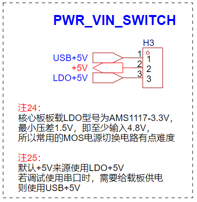

The USB-TYPE-C circuit is relatively simple. Note that the 5K1 pull-down resistors CC1/CC2 should be used to prevent the board from damaging the power supply equipment (the C port is usually supplied by the main laptop or docking station). It is recommended to add an F1 fuse with a recommended parameter of 0.5A.

2.6 Other circuit
expansion board. Since the circuit meets the project requirements, there are still a lot of redundant IOs. As a development board kit, the focus is on learning. Without considering the cost, we should adhere to the principle of not wasting resources and design more peripheral circuits to maximize all configurations.
(1) External FLASH circuit.
It can be observed that the project has just enough spare IO ports to drive a group of SPIs. Considering the module with the highest project relevance, the external FLASH circuit can be arranged so that the lookup table data and high-precision calibration data can be written into the external FLASH to meet higher algorithm requirements.

(2) External reference source (2.495V)
. The source of this circuit is unknown. I first saw the sketch of the master on Digital Home, and later saw the analysis of the master on the OSHW platform. This circuit is very useful! It is a very sophisticated high-precision voltage reference circuit scheme. The specific calculation process is given in the figure. Friends who are interested can study and analyze it in depth. In this project, it can be simply assumed that this circuit outputs a very stable 2.495V to the ADC_IN8 channel.

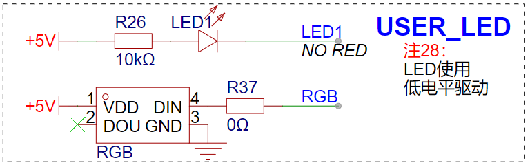
(3) Indicator and RGB circuit
The indicator LED of this circuit uses the same PC13 pin as the LED on the core board of the ground star. The difference is that it is driven by a low level. Therefore, when the PC13 is driven, when the bottom board LED is lit, the core board LED is off.
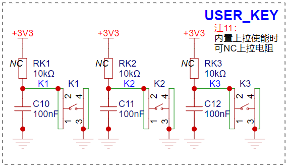
(4) Button circuit The button
circuit is designed by default to retain the position of the pull-up resistor pad and the filter capacitor so as to reduce the complexity of the code in the software design.
III. PCB design
The PCB design is almost based on the layout of the CW32 voltage and current meter case. Only all the plug-ins are replaced with surface mount as much as possible. Therefore, this part will not be elaborated. Interested readers can download this project for reference.
In the figure below, the green mark is the direction of the external power input, and the blue mark is the direction of the LDO output +5V and the USB input +5V. The relevant power ground and filter capacitors are arranged according to the suggestions in the case. It can be seen that:
(1) Green path: The external input power first passes through two 47uF chip aluminum capacitors, then through a 100nF filter capacitor, and then enters the SE8550K2 LDO. The output +5V enters the system;
(2) Blue path: The USB input +5V power first passes through the fuse (and also through a 100nF filter capacitor), and then enters the system.
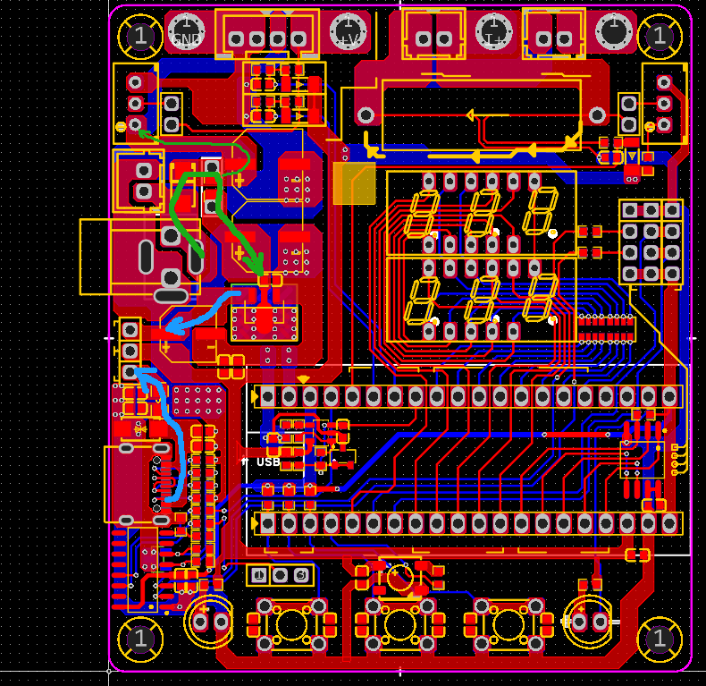
In the figure below, the sampling path of the current sensing resistor is connected according to the Kelvin method, which can effectively reduce the common mode noise interference in the sampling process:

IV. Hardware assembly
After the hardware production is completed, the PCB can be assembled according to the drawings:
(1) There are many components on the front. The figure below shows the complete soldering. If the reader needs to conduct experiments according to the example provided in the following chapter, it is recommended not to solder R0 (current sensing resistor) first to achieve the relevant circuit for using analog current input.
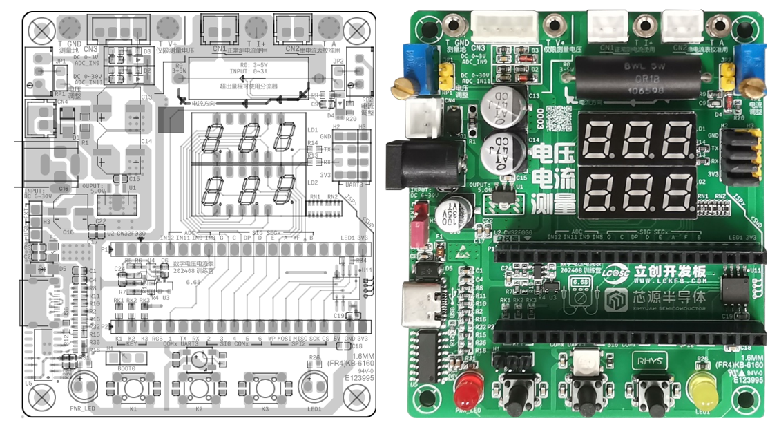
(2) There is only one ESD-related component on the other side, and it can be left unsoldered. The figure is omitted here.
V. Routine Debugging
After having the hardware, you can start learning the corresponding routines. I will guide you through the steps of the training camp experiment, reproduce and reconstruct the relevant routines for your reference:
(0) About the library function project template
This is very important, but unfortunately, even with such a thorough description as the training camp textbook, there are still many problems. Here I will reproduce the problems I encountered and provide corresponding solutions:
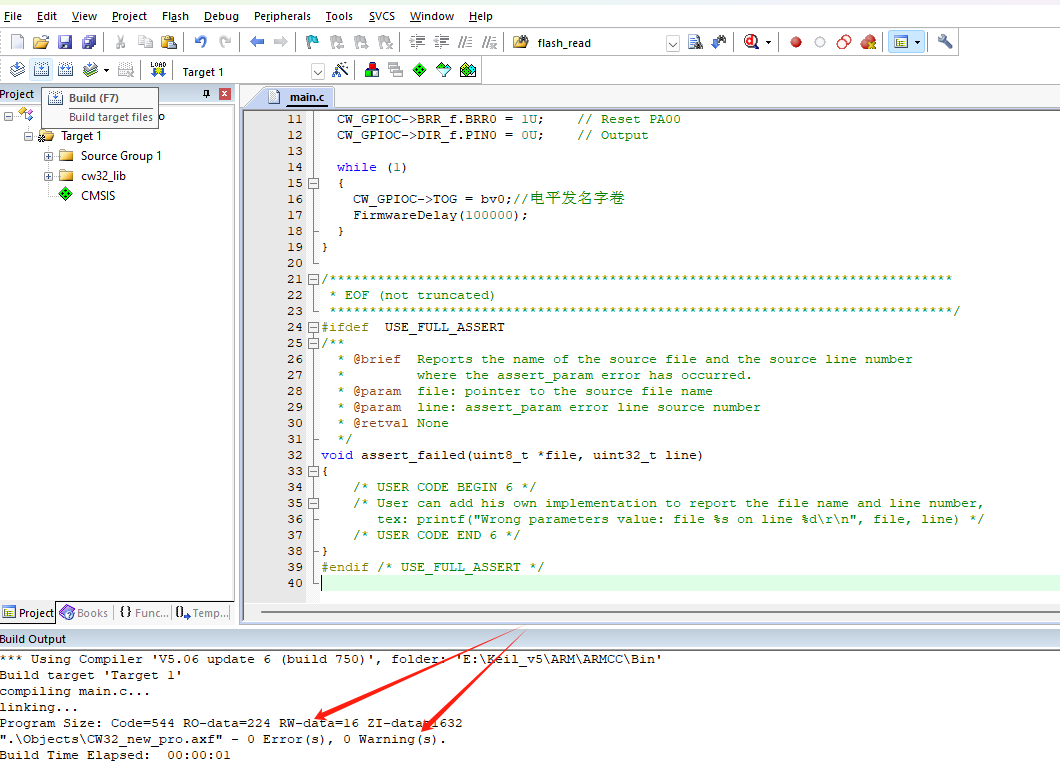
5.0.1 Error in writing routine code
As shown in the figure, it will index to line 2 and report error x 1.
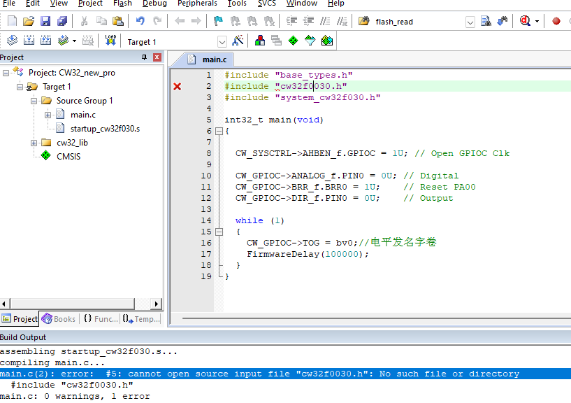
This should be a typo and needs to be corrected to: #include "cw32f030.h"
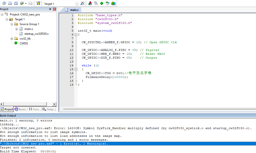
5.0.2 Error in duplicate definition
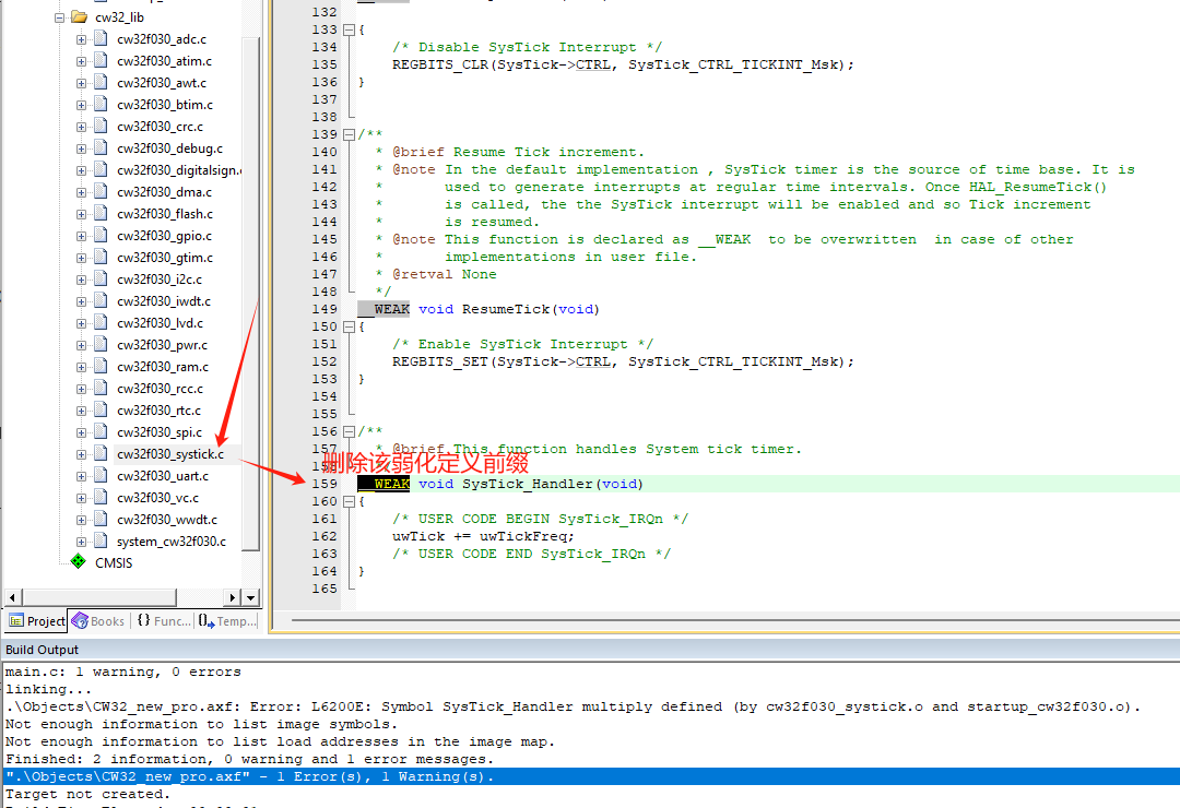
As shown in the figure, this situation is also explained in detail in the textbook. You need to open the cw32f003_systick.c file and change the weak void SysTick_Handler(void) on line 159 to void SysTick_Handler(void), that is, delete weak.
The "Unknown definition error
" issue in section 5.0.3 will always occur if the F03x firmware library is downloaded from the official website. Careful users will find a solution in the official project template.

Open the example project provided with the firmware library:
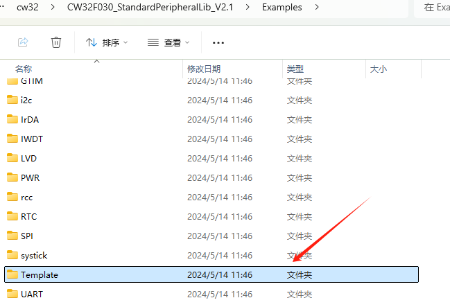
Open its MDK project, and you'll find that the example template defines the function related to the "Unknown definition error" in the main.c function!
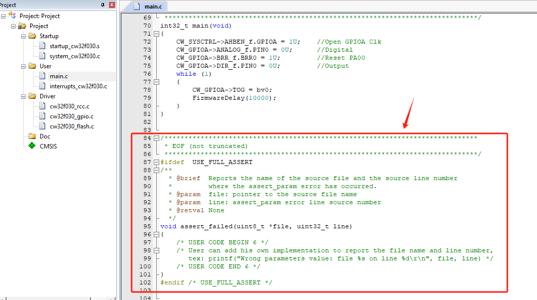
Copy this function definition code into your newly created project template to achieve zero errors and zero warnings for the first time!
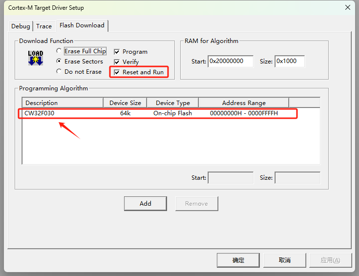
5.0.4 "Unconfigured chip download error":
The newly created project hasn't actually been configured for downloading or the downloader. If the described issue occurs, please configure as follows:
For example, using ST-LINK for downloading (DAP-LINK or other download tools can be used similarly):
STEP 1: Modify the downloader to the corresponding options and ensure the corresponding tool driver is installed on your computer!

STEP 2: Change the download method to SW download method.

STEP 3: If the target device chip list is blank, please add the corresponding chip model to avoid the "+M0 error" window popping up.
5.0.5 Recommended CW32F030C8T6 Project Template
: LCSC/Diwenxing CW32F030C8T6 Development Board Project Template <-- Click the link to get the example template, very useful!
This template categorizes different files and intentionally guides programmers to use a highly cohesive and loosely coupled development approach. In this project template, the SDK is categorized as follows:
Filename
Description
Project:
Contains project files.
Libraries:
Contains various library files, CMSIS, chip firmware library, file system library, etc.
Board:
Contains board initialization and linking files.
APP:
Contains the application program, written by the user and containing the main function.
BSP:
Contains support packages related to the underlying layer.
Module:
Mainly contains various software modules, etc.
(1) Illumination (GPIO push-pull output mode application)
The author developed the program based on the LCSC CW32F030C8T6 development board project template. Two points need to be noted here:
5.1.1 Learn how to use standard library functions to initialize GPIO and control high and low level output.

5.1.2 The DEBUG-PRINTF related parts are rewritten to use the onboard CH340C for direct debugging.
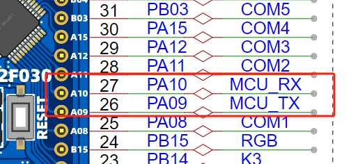
Hardware-wise, this can be understood as connecting PA09/PA10 to the USB-TYPE-C port and using CH340 for USB-TTL communication.
Reference: CW32F030_DataSheet_CN_V1.8, page 27.
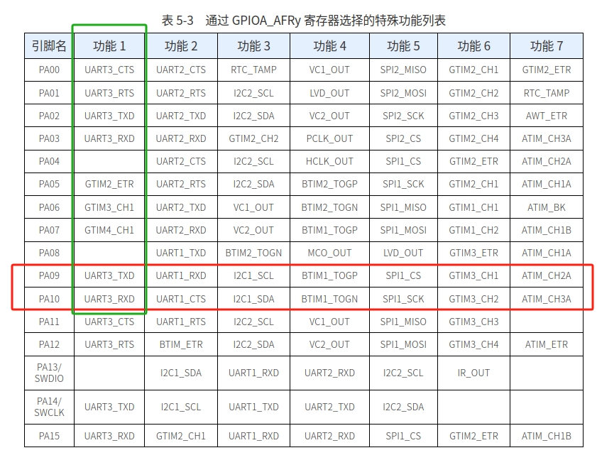
It is known that PA9/PA10 can select the special functions UART3_TXD/UART3_RXD. Therefore, the bsp_uart.c/.h parts of the template are rewritten.
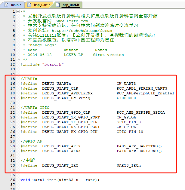
After that, simply calling printf() will quickly debug the current program! For example, the code effect of this case:

Experimental effect:

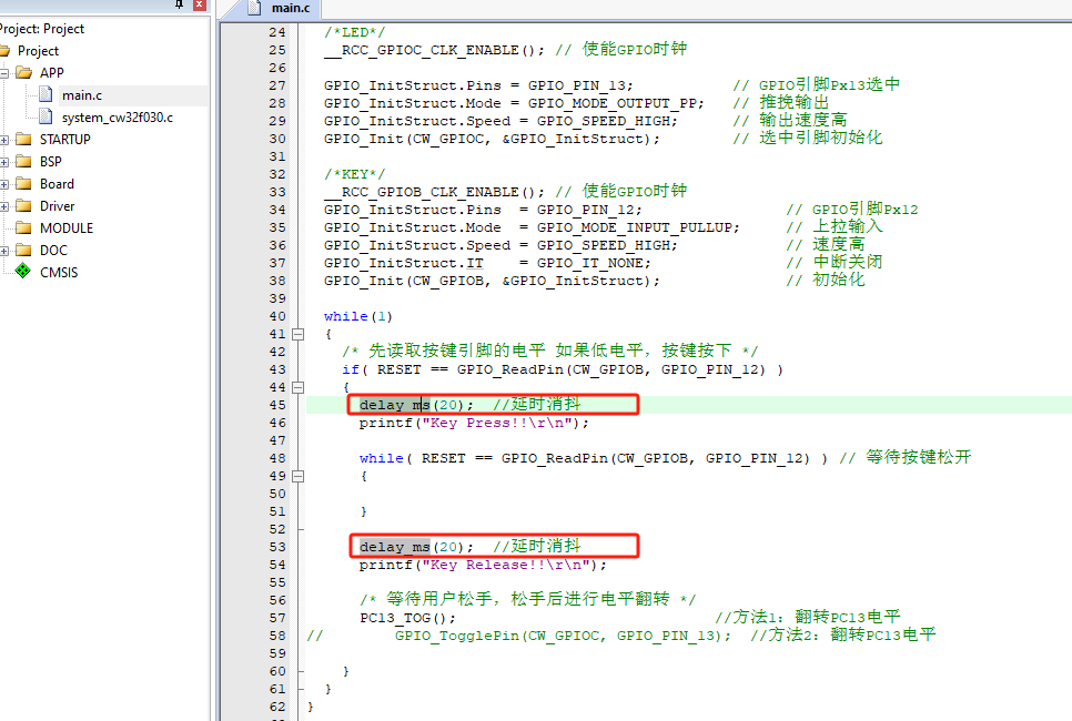
(2) Key detection (GPIO input application)
case, especially the official case, no filter capacitor is added next to the key, the light touch switch is particularly easy to generate jitter interference normal reading, at this time it is necessary to use software delay to delay debouncing:
Experimental effect:

Corresponding serial port DEBUG:

(3) External interrupt key interrupt (GPIO external interrupt application)
5.3.1 Initialize the corresponding GPIO for external interrupt configuration, pull-up/falling edge trigger
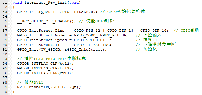
5.3.2 Register external interrupt response service function

5.3.3 Idle response

Experimental effect:

Corresponding serial port DEBUG:

(4) Timer interrupt (basic timer interrupt application)
5.4.1 Timer initialization, pay attention to enabling timer interrupt and starting timer
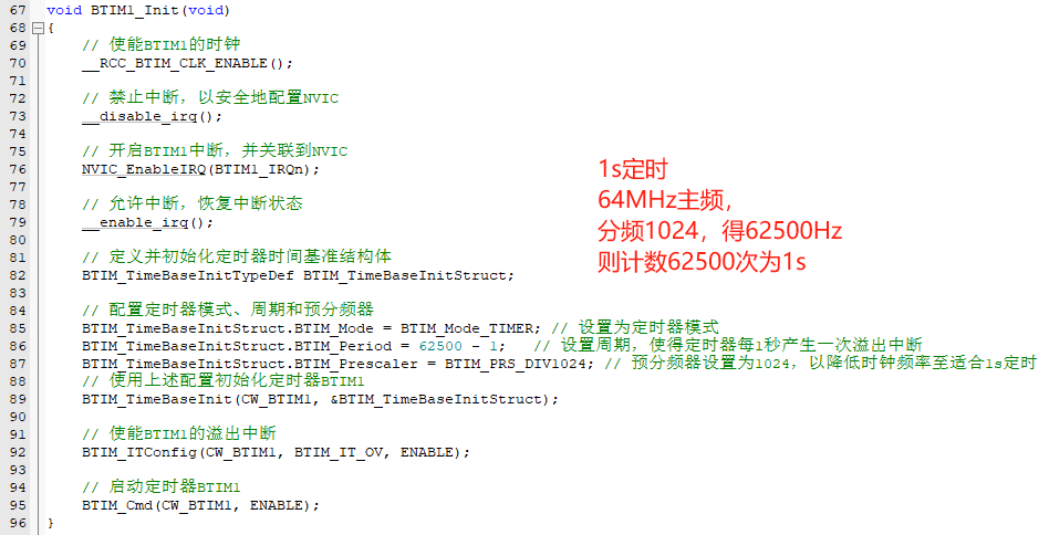
5.4.2 Register timer interrupt service function
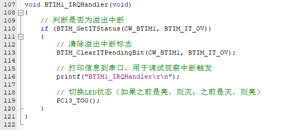
5.4.3 Initialization call, keep while(1) main thread action empty, test whether the timer can enter the interrupt

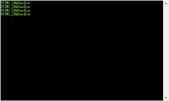
Experimental effect:

Corresponding serial port DEBUG:
(5) Digital tube display driver
5.5.1 The digital tube display principle

uses a three-digit LED display, which is a common cathode display.

To display the third digit, 1, the corresponding LED_B and LED_C need to be lit. When DIG3 = 0 and LED_B/C is 1, the third digit will display 1. Based on similar principles, different numbers, characters, or combinations of numbers and characters can be displayed. As shown in the figure below, a standard character set can be constructed based on the segment code combination. (If it is a common anode display, only the driving direction needs to be reversed, that is, the character set code is NOT operated.)
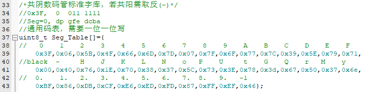
Next, it polls, based on the character set code, to determine whether A needs to be lit, whether B needs to be lit, and so on, until it determines whether DP needs to be lit. This completes the display of a single digit. This is also the conventional operation method.
5.5.2 So, let's play around a bit. In hardware design, we can notice that
the segment code control terminals used in the hardware are PA00 ~ PA07. Does this mean that we can write directly in parallel without polling?

The answer is yes, GPIOx_ODR can be used to write data in parallel.
Reference: CW32x030_UserManual_CN_V2.5 page 152.

But there will be a problem here: the standard segment code sorting is 0x corresponding to dp_g_f_e_d_c_b_a, but in hardware, it is not LED_A corresponding to PA00. It is mapped due to layout priority. Therefore, a new character array is needed:
a simple tool is written to convert it:

to get the new character array:

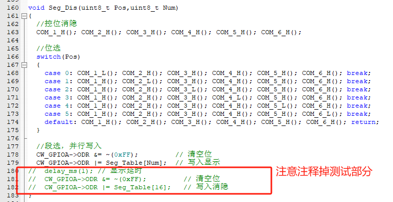
in the writing stage, parallel writing can be done directly. Note the ODR writing method. It cannot be directly assigned, otherwise it will cause other bit states to change.

5.5.3 Constructing the display test logic
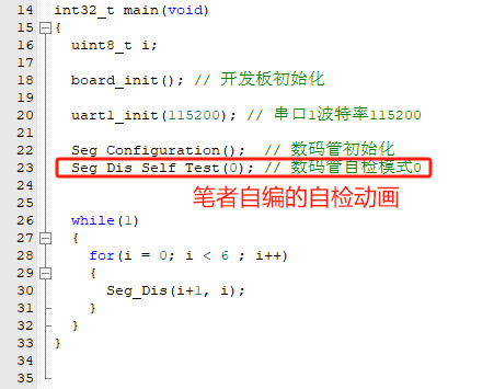
Experimental effect:

(6) Digital tube dynamic scanning display
5.6.1 Using the knowledge of the pre-set timer interrupt, configure 1ms timing

5.6.2 Construct the unit digital tube display function using parallel writing
5.6.3 Digital tube scanning function, each time enters to display 1 bit, the next time displays the next bit

5.6.4 The function of scanning and displaying the digital tube is placed in the timer interrupt to achieve the effect of timed scanning.

5.6.5 In the main thread, the value to be displayed is modified to make the experimental effect significant.

Experimental effect:
(7) 4ch ADC + DMA
5.7.1 CW32F0xx ADC principle
Reference: CW32x030_UserManual_CN_V2.5 Page 435
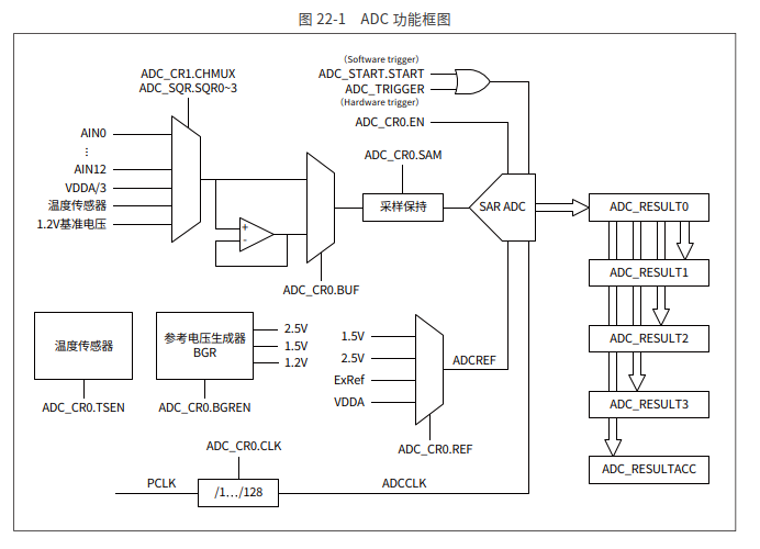
There is very important information here. It can be seen that the ADC conversion is completed and a maximum of 4 results are retained. Also, the board is configured with 4 preset ADC channels, namely ADC_IN8, ADC_IN9, ADC_IN11, ADC_IN12.
Reference: CW32x030_UserManual_CN_V2.5 Page 447

According to the project requirements, DMA is used for transfer. It is easier to implement using the scan conversion mode.
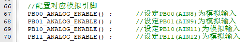
5.7.2 Configure the mapping analog pins
5.7.3 Configure the ADC basic items

5.7.4 Configure the sequence conversion

5.7.5 Configure DMA CH1 to transfer the data after ADC conversion
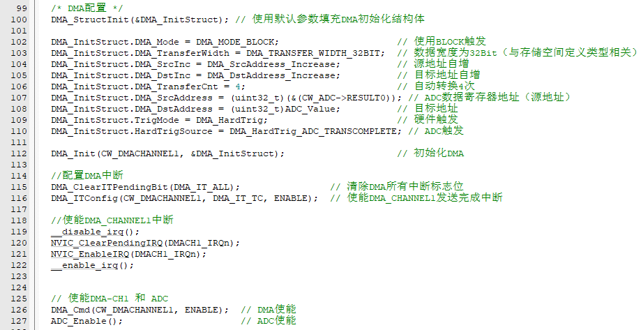
5.7.6 In the DMA CH1 interrupt, configure the number of transfers and the corresponding address reset

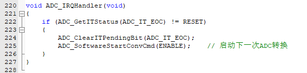
5.7.7 In the ADC interrupt, start the next ADC conversion (DMA will automatically trigger and transfer the data to the specified buffer space when the ADC is interrupted)
5.7.8 In the while(1) main thread, directly read the data transferred to the destination address by DMA after ADC conversion

Experimental effect: (where ADC_IN8 corresponds to the TL431 theoretical design 2.495V output)

(8) Mean filtering algorithm implantation
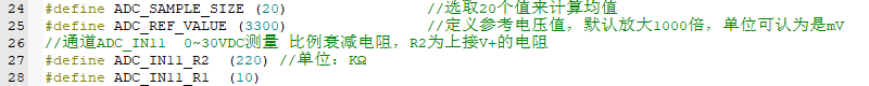
5.8.1 Set the length of the filter mean, here set to 20 points of mean
5.8.2 Every 1ms, copy the data from the ADC to the filter pool
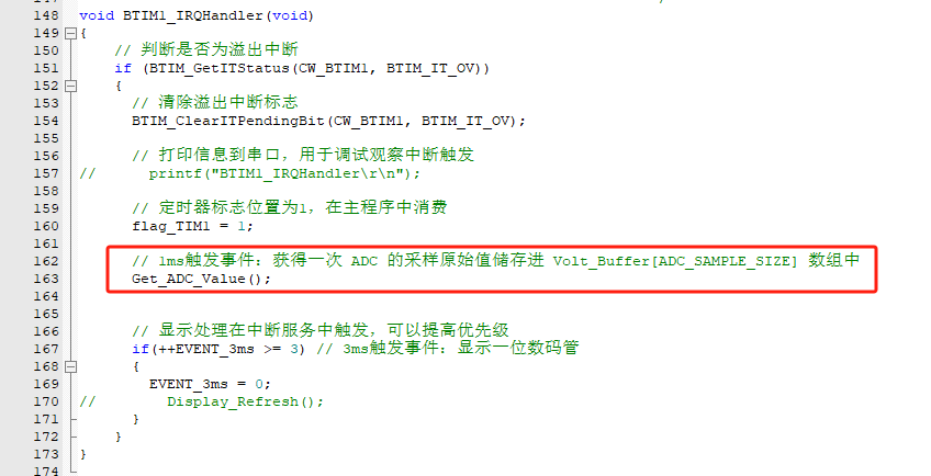
where void Get_ADC_Value(void) is fixed at 20 points, and when full, it starts from index [0] to overwrite and update the filter pool:

5.8.3 Based on the mean filtering algorithm, it is encapsulated into function
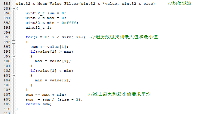
5.8.4. The main thread event reads and calculates the mean filtering output once every 300ms.

Note that >>12 here means /4096, which is used to convert the ADC value to the voltage value.
Experimental results:

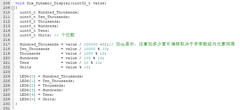
(9) 6-bit voltage display (used for subsequent test calibration pre-experiment)
5.9.1 Define the relevant values for the ADC_IN12 channel, which is the current sampling voltage channel.
5.9.2 Same as example 8, except that the channel read is changed to ADC_IN12.
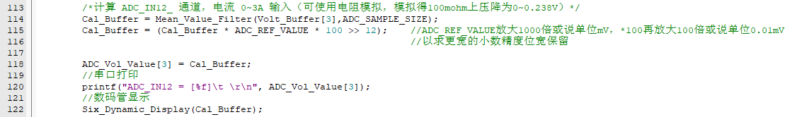
The displayed function is changed to a 6-bit display: It can be noticed that 6 bits need to process more bits.
Experimental effect:
(10) Voltage and current are displayed at the same time
. This is almost the prototype of the final code of the whole project!
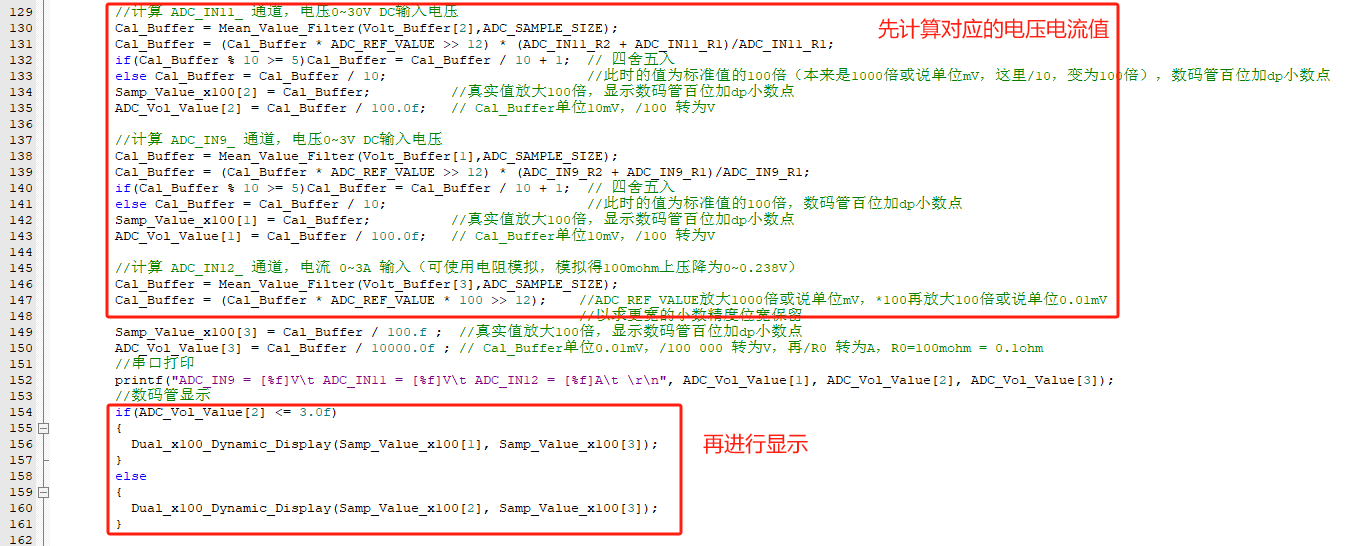
5.10.1 Based on the above experiments, add logic to calculate the corresponding voltage and current values first, and then display them.
Here, the automatic gear switching program idea is demonstrated:
if a voltage < 3V is collected, the operation voltage value of the 0 ~ 3V gear is directly switched to be displayed!
5.10.2 It can be noticed that the author has amplified the voltage/current values by 100 times. This way, at least 2 decimal places can be retained, and the function can be displayed uniformly. The display function

can be uniformly displayed with a decimal point after the hundreds place:

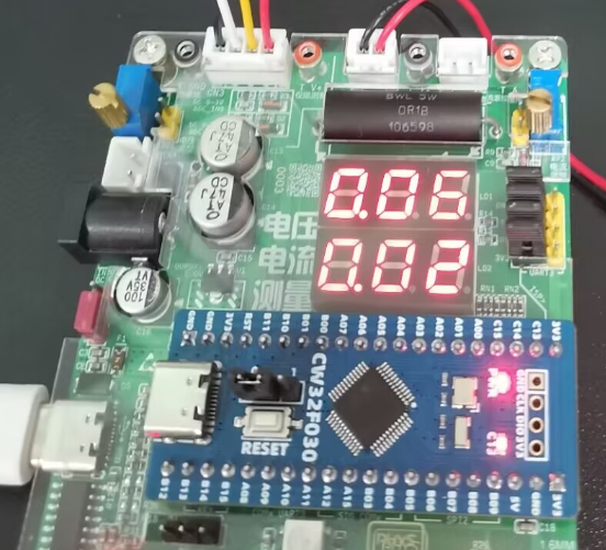
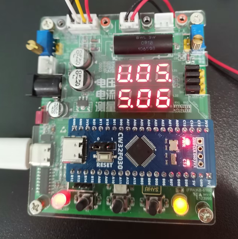
Experimental effect-1: Voltage and current are displayed at the same time. Here, the 3.3V inside the board is collected. It can be seen that the voltage difference is not large. Although there is a difference, it is close to

the experimental effect-2: Voltage and current are displayed at the same time. Here, analog current input is used. Note that R0 should not be soldered. The corresponding analog voltage drop is 0.18V, and the corresponding display current is 0.18V / 0.1Ω = 1.8xA. The theoretical and actual effects match!

(11) Digital voltage and current meter with calibration function (final version program, revised V3)
5.11.1 Design APP function
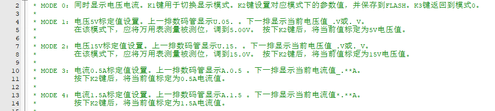
5.11.2 Use button interrupt response to APP function operation
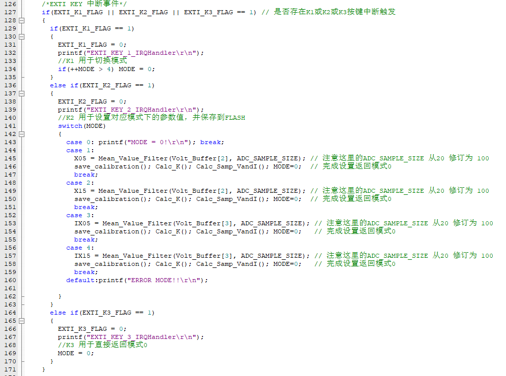
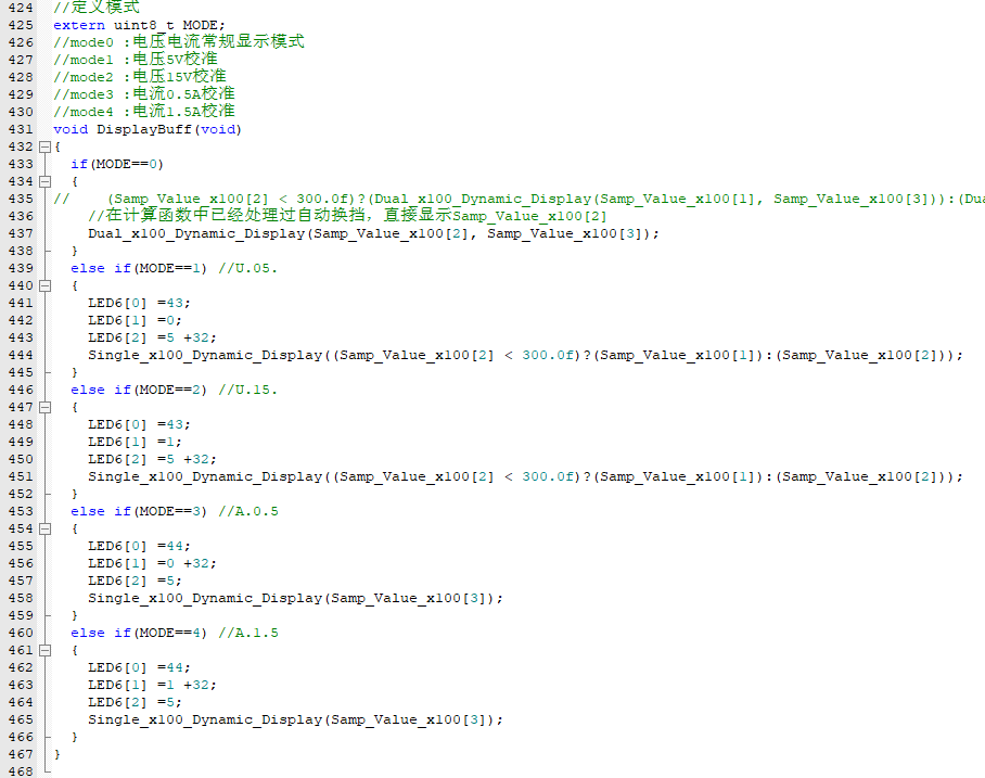
5.11.3 Different modes, different digital tube display methods
5.11.4 Under this framework, add calibration-related content
5.11.4.1 Taking the voltage channel as an example, first collect the corresponding AD value, [0, 4096).

There is a slight difference between this and the official case. I calibrated 0V. Why calibrate 0V?
As you can see, when the input is not connected, there is a reference offset. Therefore, 0V or 0A needs to be calibrated, instead of the default value of 0V corresponding to 0ADC value as in the training camp textbook program. We can output the ADC value when 0V using debug-printf: we can see that ADC_IN11 is offset by 5 LSBs.

5.11.4.2 Use two-point voltage calibration (5V and 15V are calibrated voltages). Note that the author also calibrated 0V here.
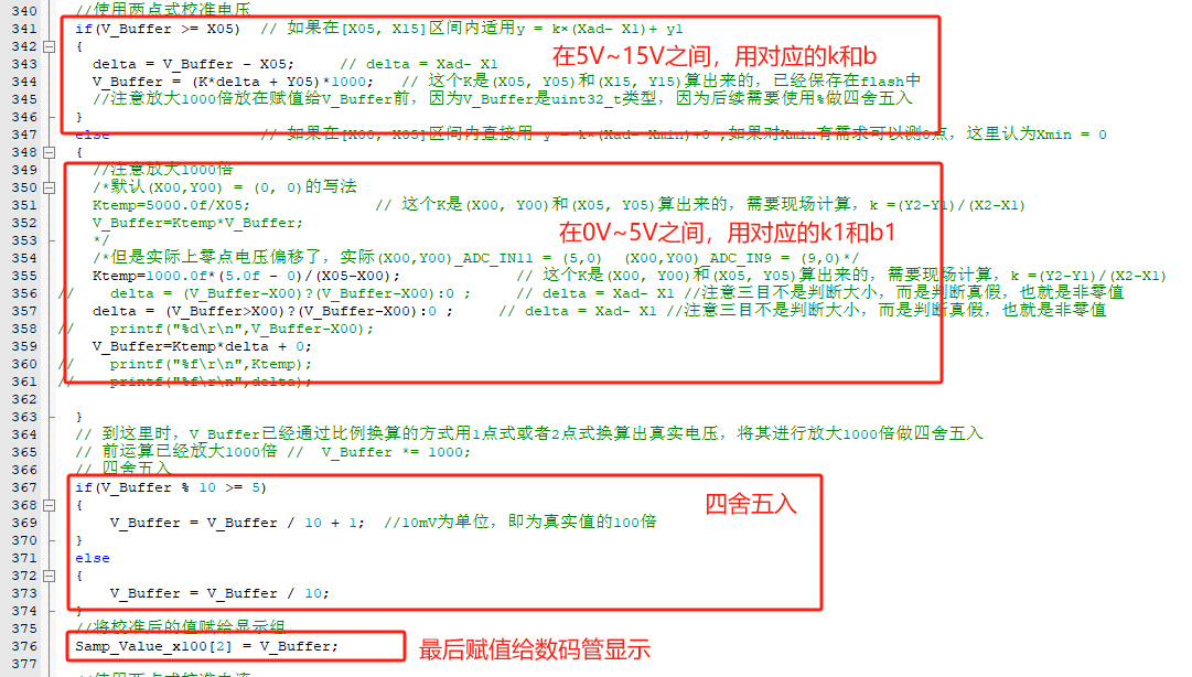
5.11.4.3 Some calibration parameters need to be written to flash so that they can be loaded and used on the next boot.
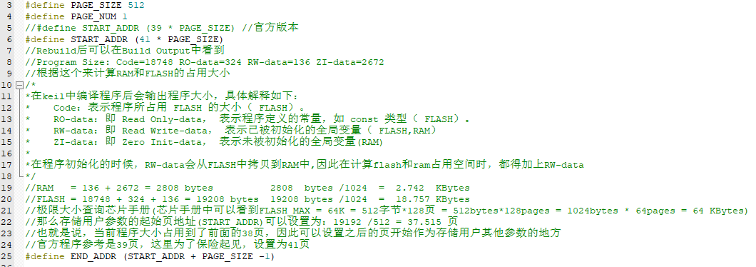
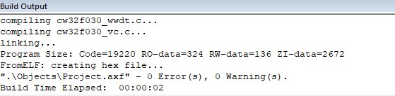
The corresponding calculation parameters can be obtained through KEIL MDK Rebuild.
Note that uint8_t FLASH_WirteHalfWords() needs to be commented out.

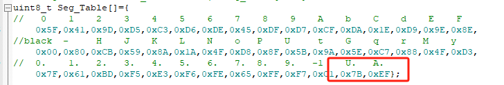
5.11.5 To display U. and A., the author added segment code library elements.
5.11.6 The APP is implemented in the main thread, responding and refreshing the display every 300ms. Experimental results
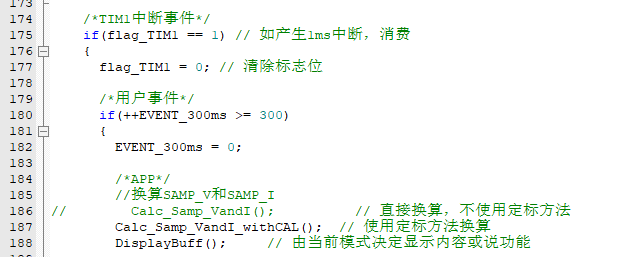
: 0-15V:
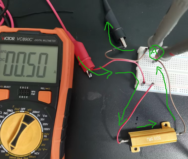
see attachment 0-15V_x264.mp4 ; 0-3A: see attachment 0-3A_x264.mp4. VI. CW32 Voltage and Current Meter Training Camp Summary: This training camp mainly focused on the methods of voltage and current acquisition and analysis. We went through the entire process from theory to practice. The hardware design standardized the current flow design and introduced concepts related to current sensing resistors, Kelvin wiring, etc. The calibration chapter, especially the current calibration, was a bit nerve-wracking, as it was my first time working with a 3A current source... This chapter describes the entire calibration process: 6.1 Connect to standard 5V (use a voltmeter for certification; higher accuracy is better), enter U.05 calibration mode. 6.2 Similarly, connect to standard 15V, enter U.15 calibration mode. 6.3 Current calibration is crucial (it's recommended to use a high-power resistor). The diagram illustrates the direction of current flow and the position of the ammeter in series. 6.4 Connect to standard 0.5A (use an ammeter for certification; higher accuracy is better), enter A.0.5 calibration mode . 6.2 Similarly, connect to standard 1.5A, enter A.1.5 calibration mode. VII. Open Source Code: The open source code is attached and includes all the code from Chapter 5. It has been personally tested and is effective. Video demonstration available in the attachment or on Bilibili: https://www.bilibili.com/video/BV1E1WieHEhk/ The above text is all learned during this training, original and shared here in the hope that it can help solve similar problems in the future! ------------------End of Article-------------------------------------------------------END--LINE-----


 京公网安备 11010802033920号

 Am29LV160BB90WCCB


