Update notes
2023.10.23: Uploaded the test2 compressed package for public testing of unlimited downloads of STC51 microcontrollers.
The task requires
implementing air-to-ground code download for STC 51 microcontrollers, air-to-ground code download for Arduino Nano, and air-to-
ground download and debugging of Keil 5 software for STM32, CKS32, and GD32 microcontrollers. Bilibili demo video link: https://www.bilibili.com/video/BV1em4y1w73B/?spm_id_from=333.788&vd_source=dbc0eac6cacf8cb212bed2f4e771e112
Bilibili soldering tutorial video link: https://www.bilibili.com/video/BV1v14y1j7r6/?spm_id_from=333.788&vd_source=dbc0eac6cacf8cb212bed2f4e771e112
The principle behind the project is
that the USB transmitter generates a CMSIS DAP device and a CDC serial port device. CMSIS... DAP devices can be configured as downloaders in Keil software, and CDC serial devices can be opened as serial devices using a serial port debugging assistant.
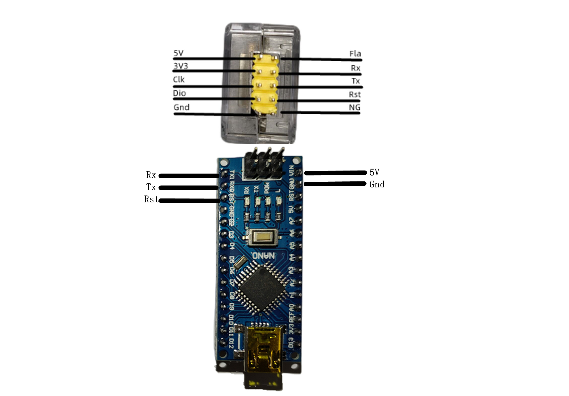
The receiver's Dio and clk pins serve as the SW download port (in this case, the negative power supply terminal should ideally be connected to Gnd), while Rx and Tx serve as the wireless serial port, which can also be used for downloading to the STC89C52RC and Arduino NANO (in this case, the negative power supply terminal should ideally be connected to NG).
The transmitter and receiver establish Wi-Fi communication via TCP. The transmitter acts as the AP, and the receiver acts as the STA. Because the serial port and SW download share the same channel, using both simultaneously will slow down the process or even cause errors. Regarding
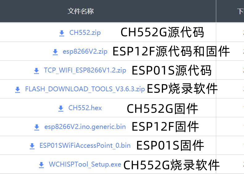
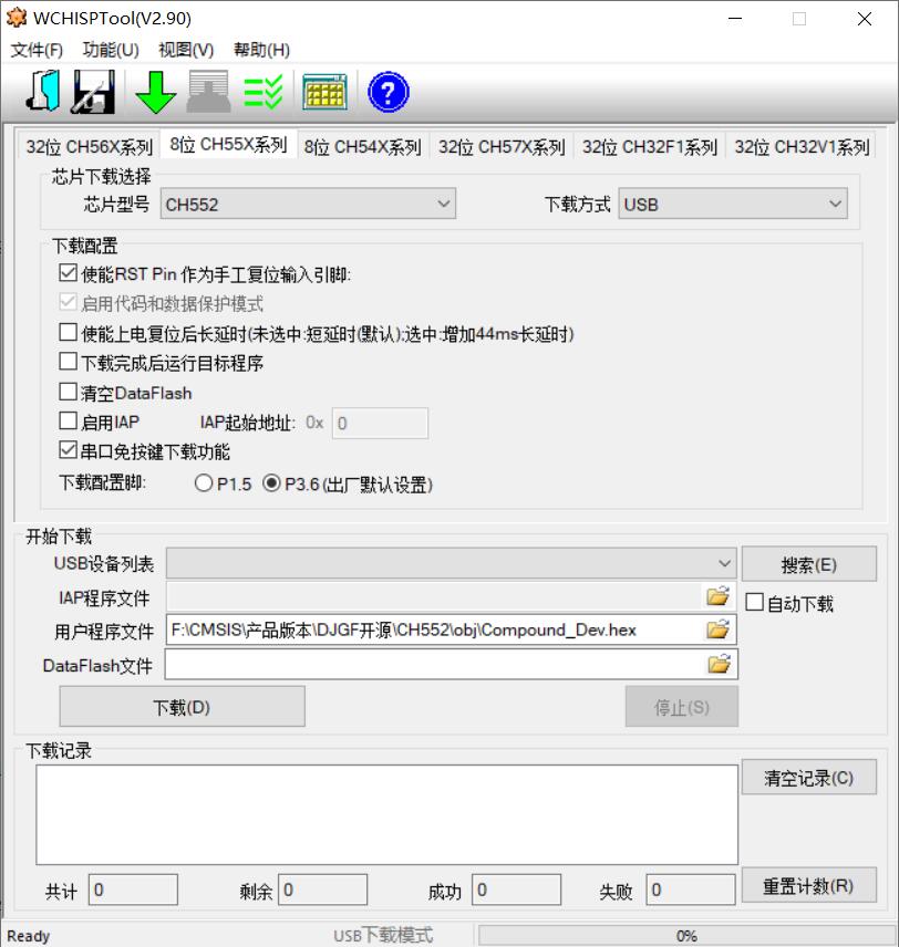
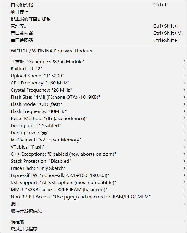
the ESP01S, it is essential to purchase the official Anxinke version and program it before soldering, as programming after soldering is inconvenient. You can choose to use programming software or Arduino IDE for programming. The specific programming configuration is as follows: CH552 programming method: Press and hold the button on the computer before connecting it, then release the button and open the programming software WCHISPTool. The specific configuration is as follows: ESP12F microcontroller programming method: The Fla pin header is connected to the ESP12F's IO0, so use a USB-to-TTL module for downloading. Reverse the Tx and Rx connections, connect Fla to Gnd, power on the USB-to-TTL module first, then power on the microcontroller via Type-C. You can choose to use programming software or Arduino IDE for programming. The specific programming configuration is as follows: Acrylic shell purchase address: https://item.taobao.com/item.htm?spm=a1z09.2.0.0.6b752e8dQAsOIG&id=536932505082&_u=l2otn78942e7 Arduino wiring diagram is as follows: STC51 wiring diagram is as follows: The STM32 wiring diagram is as follows: Notes : 1. Components should be based on the schematic. Replacing tantalum capacitors with ceramic capacitors may result in shorter communication distances and download errors, or even complete unusability. 2. The Zener diode and SR05 in the circuit are protective devices and do not need to be soldered; this will not affect normal function. Note that it is ESP12F, with the suffix "F" . 3. When downloading firmware, for both ESP01s and ESP12f firmware, the number at the end of the firmware filename represents the Wi-Fi name. Only firmware with the same number suffix can establish communication. If multiple pairs are used, each needs to be programmed with a different number suffix. Don't forget to burn the ESP01S; the LED won't stay constant without burning it. 4. For downloading ESP12, I used a USB-to-TTL adapter with three cables: RX and TX reversed, and Fla connected to the USB-to-TTL GND connector. First, plug the USB-to-TTL adapter into the computer, then plug the Type-C power cable into the computer. The download baud rate was 115200, and it succeeded every time. To download again, you need to unplug the Type-C cable and plug it back in. The USB-to-TTL adapter doesn't need to be unplugged. 5. When downloading .sw, using excessively long or low-quality DuPont cables can easily cause errors. It is recommended to buy pure copper DuPont cables.


 京公网安备 11010802033920号

 NTE308


