Compared to the original project: 1. Added multimedia keyboard functionality. 2. Matrix keyboard reading changed to parallel output and serial output (microcontroller reads serial data), enabling full key rollover (multiple key presses on the matrix keyboard result in incorrect data, but the program wasn't written for this; I'm lazy). 3. Changed the microUSB interface to a TYPE-C port. 4. Uses monochrome backlighting; the backlight illuminates when a key is pressed and turns off if no key is pressed for a period of time; otherwise, it resets the count when a key is pressed. 5. The encoder is muted when pressed, and its forward and reverse rotation adjusts the volume. (There might be some jitter, but it works...) There was also a version with a USB 2.0 docking station, but that's gathering dust; I have too many docking stations on my computer.
The code is rough, but it's usable. There are just too many projects; I can't finish them all. I really can't finish them all. I hope an expert can complete the code.
Current features: The left row has multimedia buttons: browser, audio player, next track, and pause.
The right side has a numeric keypad; pressing the key lock turns the numeric keypad into arrow keys. (The hardware for the buttons can achieve full N-key rollover, but the software only implements single-key operation based on the priority value of the key values within the program. This part can be modified to allow multiple key presses to become a single shortcut.)
Pressing the encoder mutes it, rotating clockwise increases the volume, and rotating counterclockwise decreases the volume. (This part has a bug.)
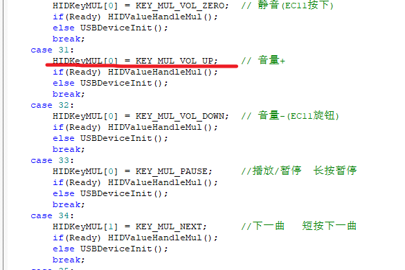
Modifying the key values is simple; there's a while...case[x] in the main function. Refer to the screenshot below for details; comparing the HID scan values will make it clear.
Recommended HID scan key value reference: https://blog.csdn.net/u011119684/article/details/124978540 .
There are many online tutorials for programming CH552 microcontrollers. Press the switch on the back of the PCB, plug it into the C port, and you can program it using the official software.


code.202307062042.zip
PDF_ALPHA KEY C03.zip
Altium_ALPHA KEY C03.zip
PADS_ALPHA KEY C03.zip
BOM_ALPHA KEY C03.xlsx
96385
VFD-ESP32-Clock
VFD clock
This is a DIY project for building a VFD clock with an ESP32S2, IVL2-7/5 VFD tubes, and a ULN2803 Darlington transistor array, powered by an LM9022 and an XL6007.
Source code: https://github.com/dasudiy/esp32-vfdclock
PDF_VFD-ESP32-Clock.zip
Altium_VFD-ESP32-Clock.zip
PADS_VFD-ESP32-Clock.zip
BOM_VFD-ESP32-Clock.xlsx
96387
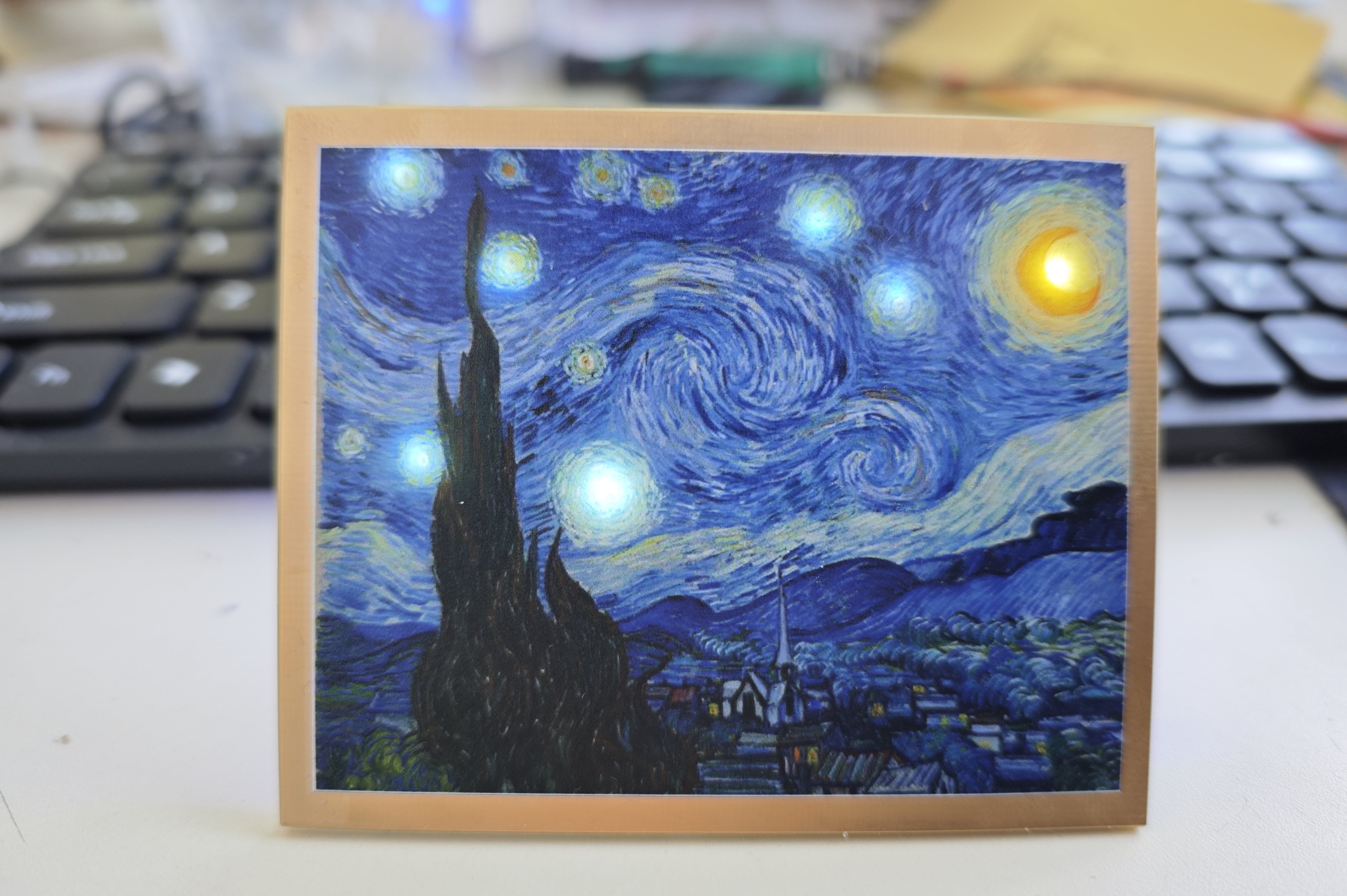
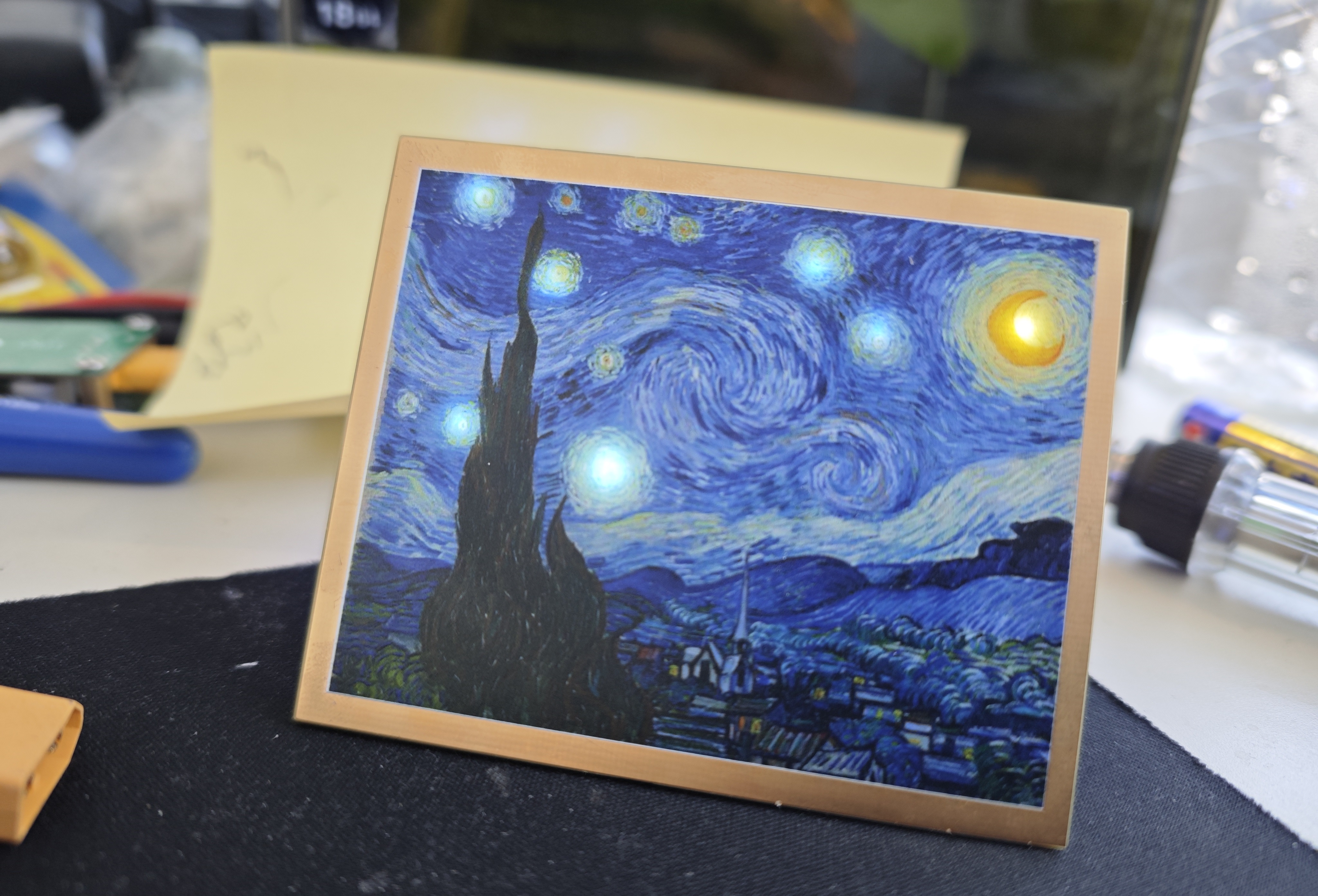
Van Gogh's Starry Night - Light Painting
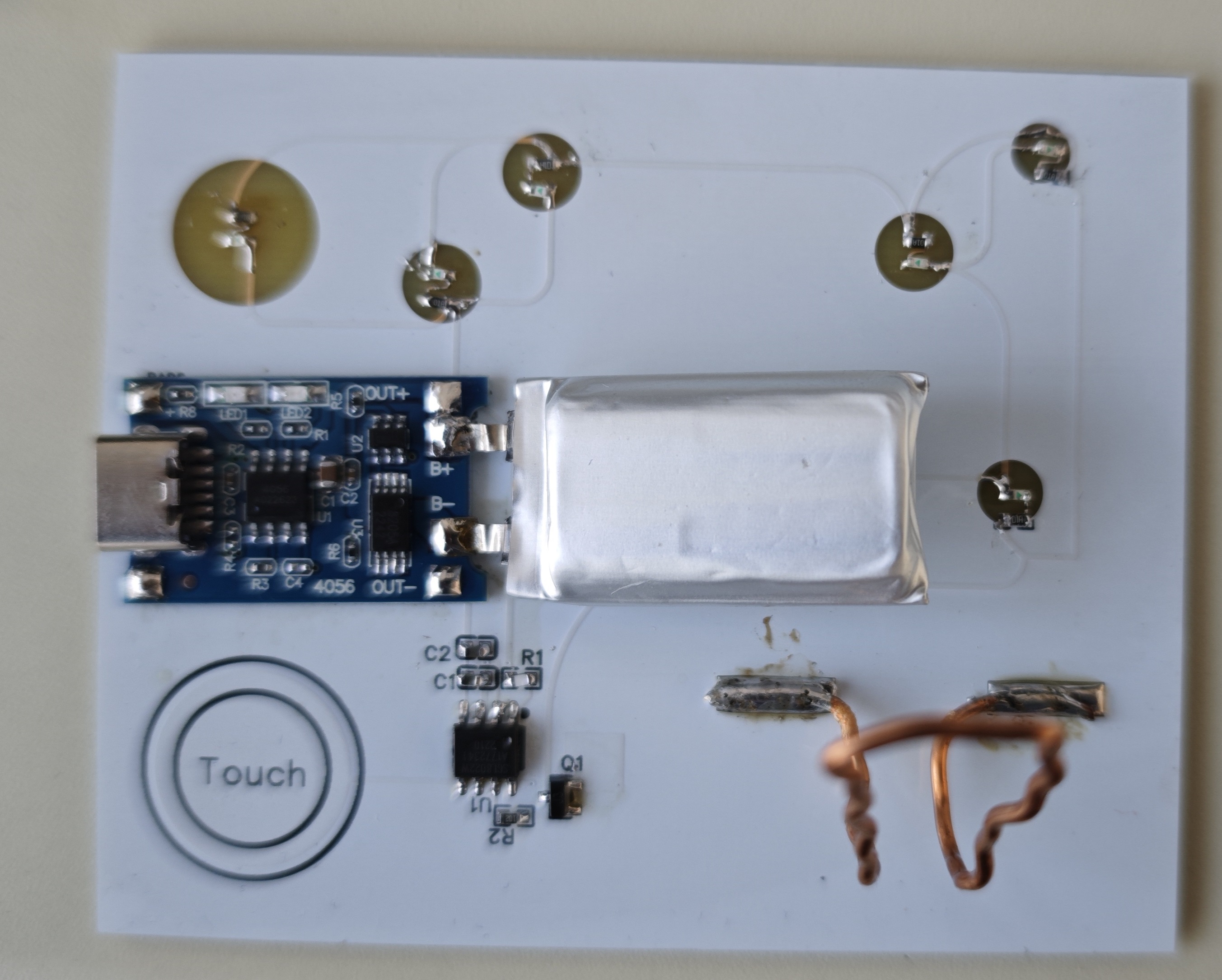
Using JLCPCB color screen printing, a battery and LED were added behind Van Gogh's Starry Night, making it a nice desktop ornament.
In this renovation, art and modern technology are ingeniously blended, with LED lights illuminating Van Gogh's Starry Night. These shimmering lights, like stars in the night sky, are both dazzling and warm, infusing the painting with new life and a sense of mystery. The moon, like a dreamlike guide, leads viewers into the wondrous world of art.
This is not merely a simple renovation, but a humanized interpretation of Van Gogh's work. The soft glow of the LEDs not only enhances the painting but also allows viewers to seemingly travel through time, personally experiencing Van Gogh's emotions and inspiration during creation. This warm starry night is no longer just static beauty on the canvas, but a living entity that resonates with us.
Through this renovation, we have used modern technology to inject new inspiration into traditional art, creating a completely new aesthetic experience for viewers. This starry night painting is no longer just a tranquil artwork, but
an art space that resonates with and co-creates with the viewer. May this renovation be your tribute to Van Gogh, and may it bring viewers a richer and more emotional artistic journey.
When making a circuit board, you should add a note: "No special processes used, no liability for processing" to ensure that the board has a full border

with components on the back side underneath.
ee7349f4ee639521245a3d87b0e8c53.jpg
PDF_Van Gogh's Starry Night_Light Painting.zip
Altium_Van Gogh's Starry Night_Light Painting.zip
PADS_Van Gogh's Starry Night_Light Painting.zip
BOM_Van Gogh's Starry Night_Light Painting.xlsx
96388
Joint Laboratory ---- STM32F407ZGT6 Development Board
A development board based on the STM32F407ZGT6, used to replace the Explorer from Zhengdian Atom.
This development board, based on the STM32F407ZGT6, is used to replace the Explorer screen of the Zhengdian Atomic microcontroller. The only difference in pin configuration is the BL backlight pin. It can use Zhengdian screens, but requires modification of the example code. The backlight pin
supports DFU, UART, and SWD programming. DFU and UART programming require BOOT0 configuration (pressing the BOOT0 button while powering on). UART also supports automatic downloading, requiring software configuration. It
integrates 6 custom buttons, CAN, touch, DAC, ADC, I2S audio, eight LEDs, ultrasonic sensor, photosensitive sensor, relay, buzzer, wireless module, DHT20, memory card, external serial port, etc., bringing out all I/O. The
wireless module is compatible with the original Zhengdian
board. Some test code and board schematics are attached below; you can cut the board yourself.
Thanks to the joint laboratory for their support of this project.
F407 Development Board Bottom Case.DXF
test.zip
PDF_Joint Lab---- STM32F407ZGT6 Development Board.zip
Altium Joint Lab - STM32F407ZGT6 Development Board.zip
PADS Joint Lab - STM32F407ZGT6 Development Board.zip
BOM_Joint Lab---- STM32F407ZGT6 Development Board.xlsx
96389
LDO adjustable step-down module
A simple step-down module that accepts a 12V input and allows for adjustable output voltage via a slider; compact and convenient.
The step-down function is achieved by using the ams1117-adj, and the output voltage can be adjusted by a sliding resistor.
QQ Video 20240110210820.mp4
PDF_LDO Adjustable Buck Module.zip
Altium_LDO Adjustable Buck Module.zip
PADS_LDO Adjustable Buck Module.zip
BOM_LDO Adjustable Buck Module.xlsx
96390
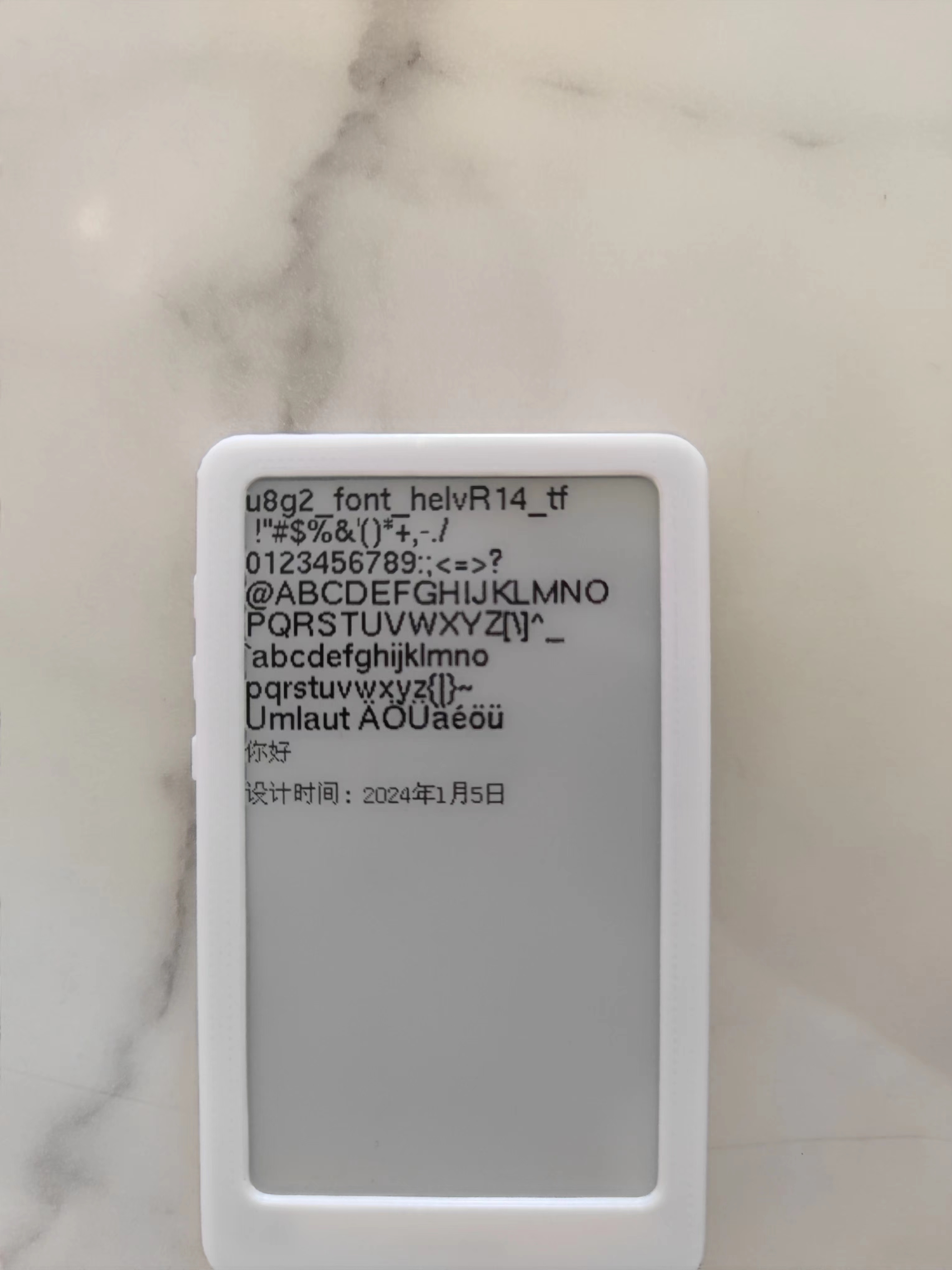
ESP32 E-ink e-reader
An ESP32-based e-ink driver board, compatible with all 24-pin boards.

The charging/discharging
board provides charging/discharging circuitry and a battery terminal for battery power. It also has an SD
card
slot, allowing you to read SD card content using an ESP32 microcontroller to display images, books, dates, etc.
The e-ink screen
driver board is generally compatible with 24-pin e-ink screens . The attached
code
includes sample code for a 3.71-inch e-ink screen, which can power on and display correctly, utilizing the GxEPD2 and U2g8 libraries.
exampleCode.zip
PDF_ESP32 E-ink Reader.zip
Altium_ESP32 E-ink Reader.zip
PADS_ESP32 E-ink Reader.zip
BOM_ESP32 E-ink Reader.xlsx
96391
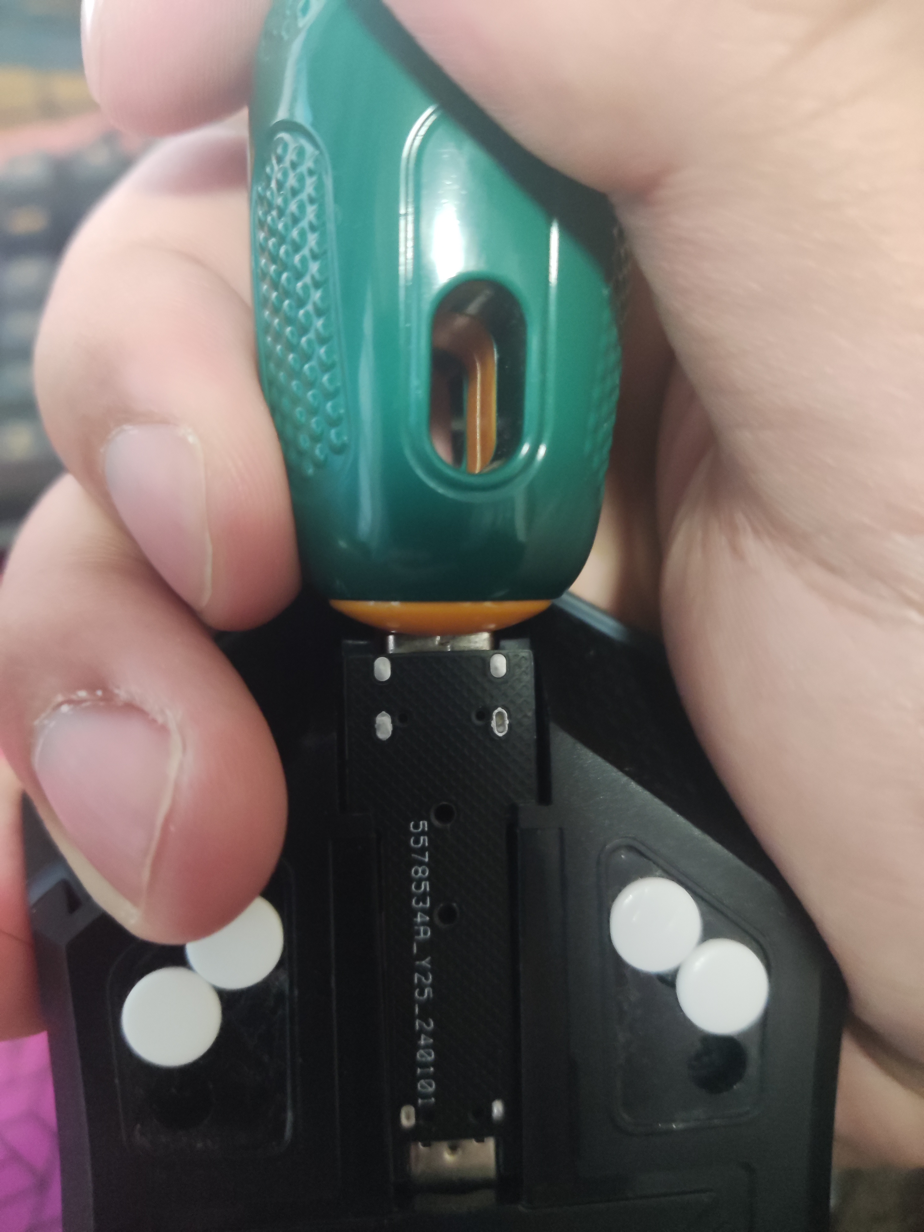
MS420DS MicroUSB to Type-C
MS420DS MicroUSB to Type-C
The MS420DS MicroUSB to Type-C adapter
cable that comes with the MS420DS is ridiculously tight, deep, and oddly shaped, making it difficult to plug in and unplug. So I made this one.
You'll need to purchase one Type-C 16-pin female connector (less than 0.2 yuan each), one MicroUSB male connector (less than 0.5 yuan each), and two 5.1K... The 0603 resistor (price is almost negligible), after deducting the cost of the PCBs I get from JLCPCB twice a month (which I get for free), is less than 1 yuan, but shipping costs might be a significant portion.
In the previous version, based on other PCBs, the PCB diagram had a 22Ω resistor in series on both the D+ and D- lines. Later, I thought it might not be necessary, so I replaced it with two 0Ω resistors. Could someone knowledgeable advise whether it's better to add or remove the 22Ω resistor?
The 5.1K resistor for Type-C is for the device to be recognized as a powered device; whether it's necessary is unknown (I know nothing about this).
When soldering, don't pile up too much solder around the four mounting pins of the Type-C casing. The groove under the MS420DS roller is larger than the Type-C female connector. Not much solder buildup might prevent the adapter board from being inserted properly
, making installation very tight. Align the MicroUSB port and insert it slightly, about 1-2mm. If it's too tight, you can use a larger screwdriver or something similar, with the handle pointing towards the Type-C port, and push it in. After that, about 3-5mm of the MicroUSB male connector should still be sticking out. The PCB should be about 1-2mm away from the MicroUSB female connector.
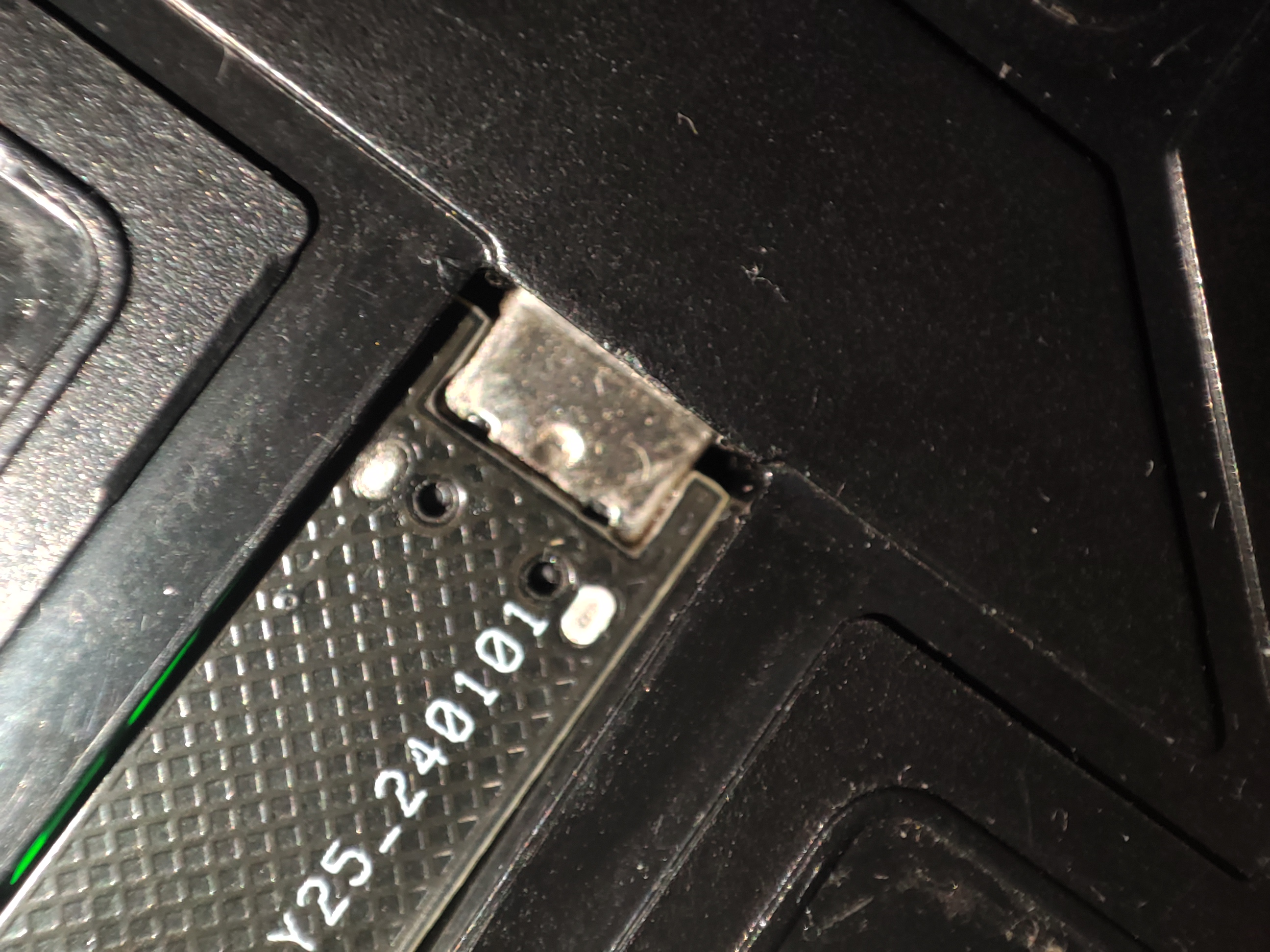
Theoretically, the adapter board should be able to be removed after insertion. There are two small holes, about 1mm in diameter, in the middle of the adapter board. I was thinking of using tweezers to push the adapter board out, but it's too tight, and I was afraid of making it difficult to push out, so I don't have a separate picture of the adapter board.
PDF_MS420DS MicroUSB to Type-C.zip
Altium_MS420DS MicroUSB to Type-C.zip
PADS_MS420DS MicroUSB to TypeC.zip
BOM_MS420DS MicroUSB to TypeC.xlsx
96392
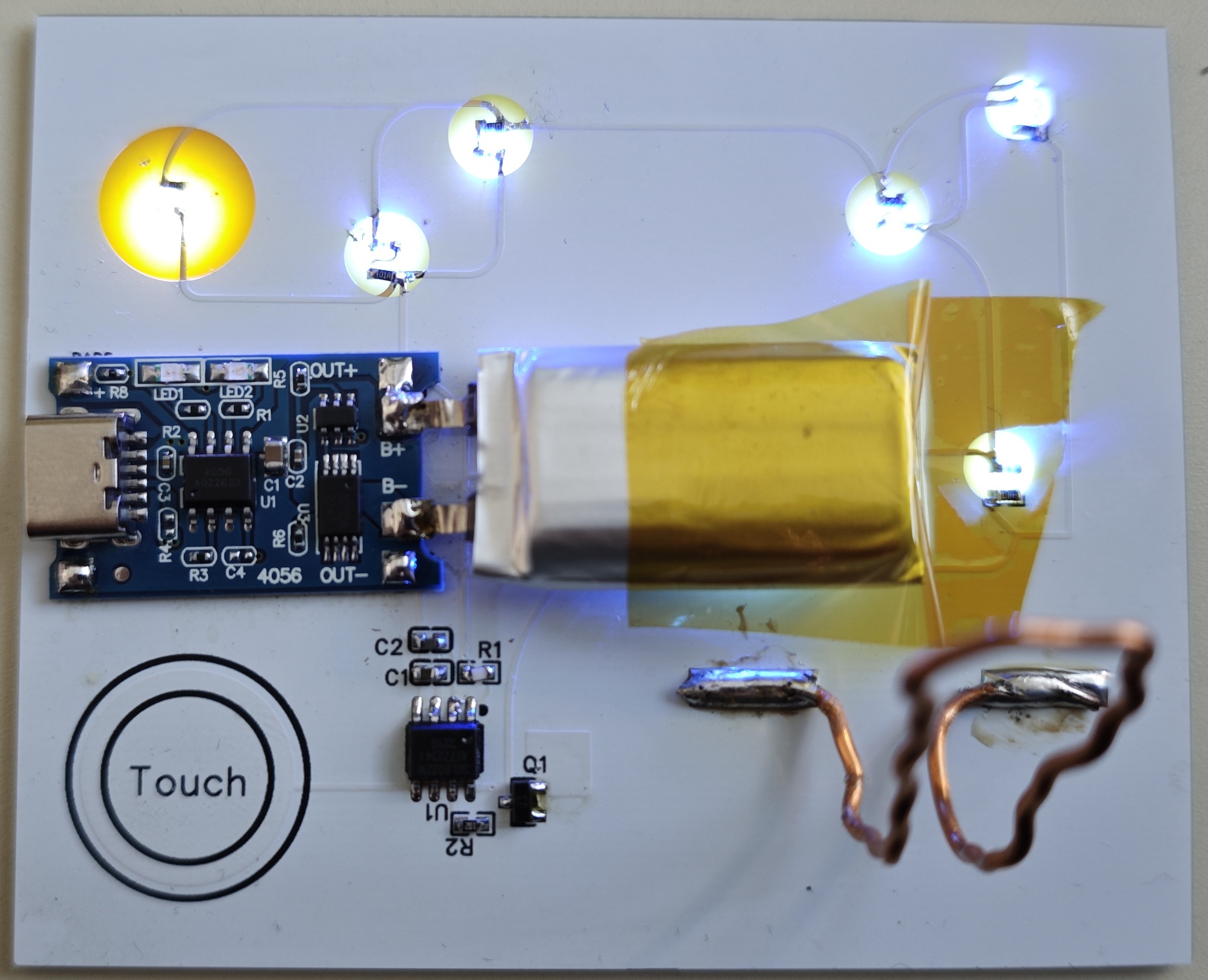
Tuozhu LED light base charging board
This printed circuit board is designed for Tuozhu LED lights and comes with a 3D model.
This printed circuit board is designed for Tuozhu LED lights and includes a 3D model STL file.
Functions: The Tuozhu LED light base charging module provides charging, protection, and voltage boosting functions.
The positive and negative terminals of the battery icon on the PCB are connected to the positive and negative terminals of the battery. The 5V and GND outputs are silkscreened; only 5V is output, which can be connected to the positive and negative terminals of the LED. The Type-C port is the charging interface. When Type-C is connected, it powers the battery and provides power; when Type-C is not connected, the battery powers the battery.
The unsilkscreened pin headers (pins 2 and 3 of the five-pin header, i.e., the pins with copper contacts) are connected to the switch or directly short-circuited (a direct short circuit disables the switch function).
Base cover.STL
Base .STL
PDF_Tuozhu LED Light Base Charging Board.zip
Altium_Tuozhu LED light base charging board.zip
PADS_Tuozhu LED Light Base Charging Board.zip
BOM_Tuozhu LED Light Base Charging Board.xlsx
96399
Based on IR2104 bipolar SPWM inverter
SPWM single-phase inverter based on RI2104
This is a single-phase SPWM inverter based on the RI2104 microcontroller
with complementary SPWM outputs
and a 12V auxiliary power supply. The MOSFETs, inductors (2MWh), and capacitors (8UF) are
selected based on the input/output parameters.
f334c8t6_spwm.zip
PDF_Based on IR2104 Bipolar SPWM Inverter.zip
Altium-based IR2104 bipolar SPWM inverter.zip
PADS_Based on IR2104 Bipolar SPWM Inverter.zip
BOM_Based on IR2104 Bipolar SPWM Inverter.xlsx
96400
electronic


 京公网安备 11010802033920号

 HI5810JIJ


