1. Introduction
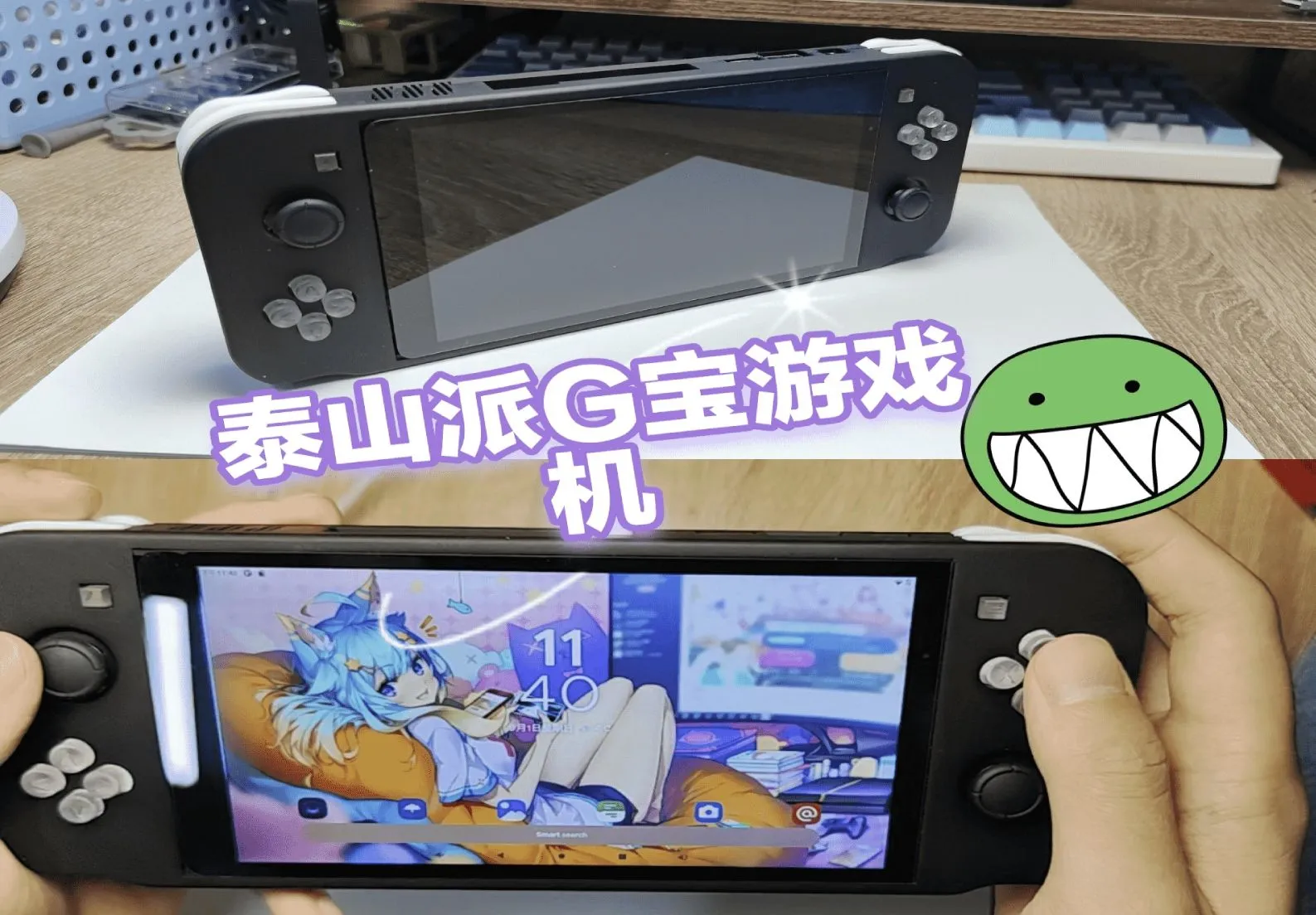
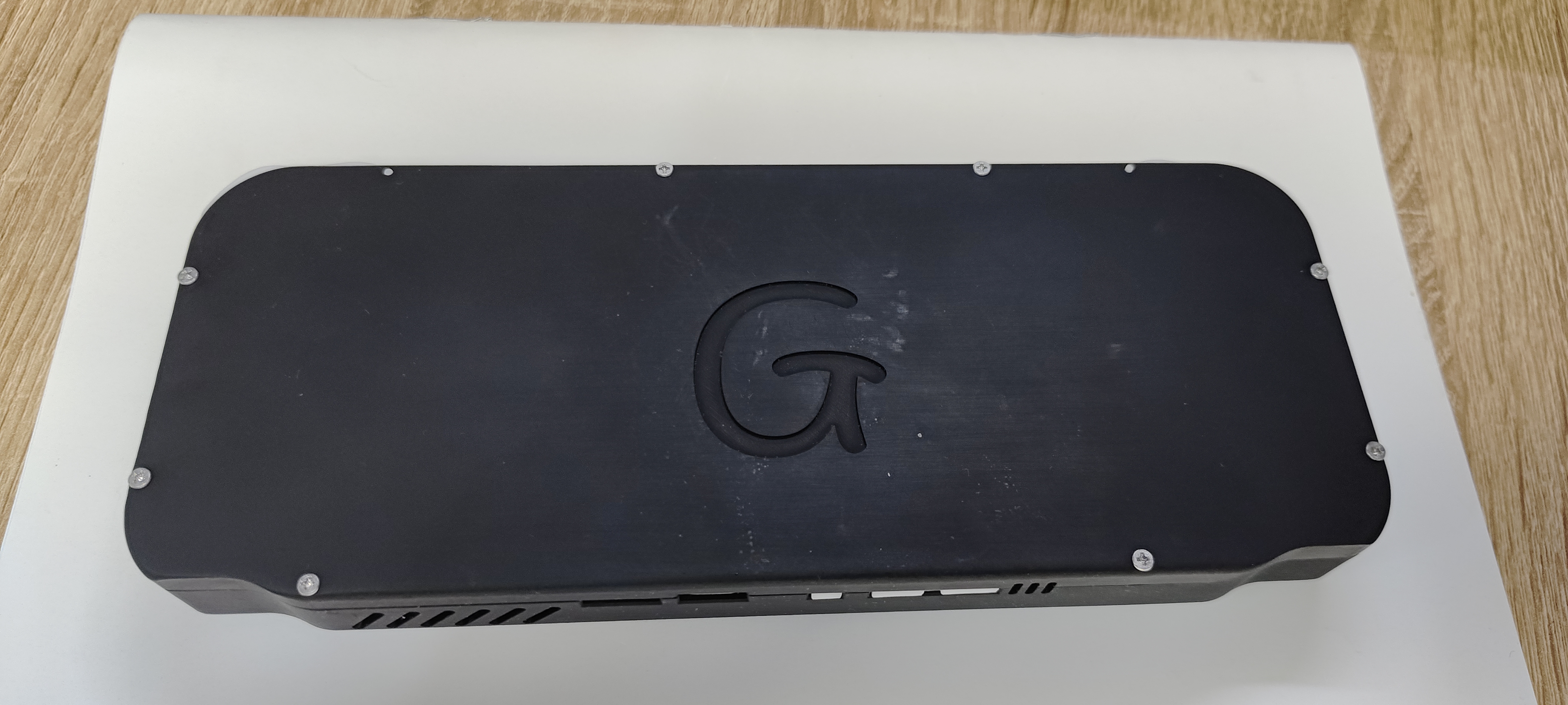
This is a "Little Dolphin" smartphone based on the LCSC Taishanpai Development Board and Android 11/Ubuntu 20.04.
V4 version demonstration video [Bilibili] I made a smartphone!!! Meeting daily needs?
V3 version demonstration video [Bilibili] I made a budget "phone" that can shoot videos? Play Genshin Impact?
2. Project Overview
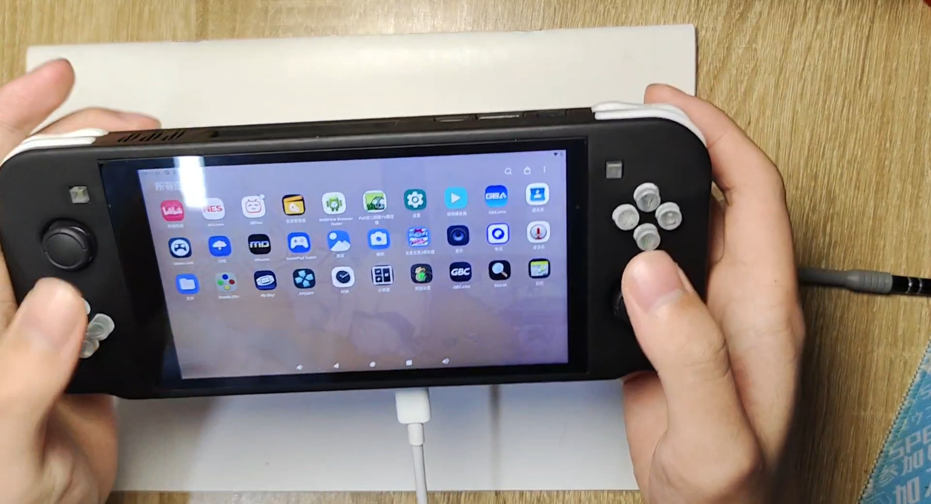
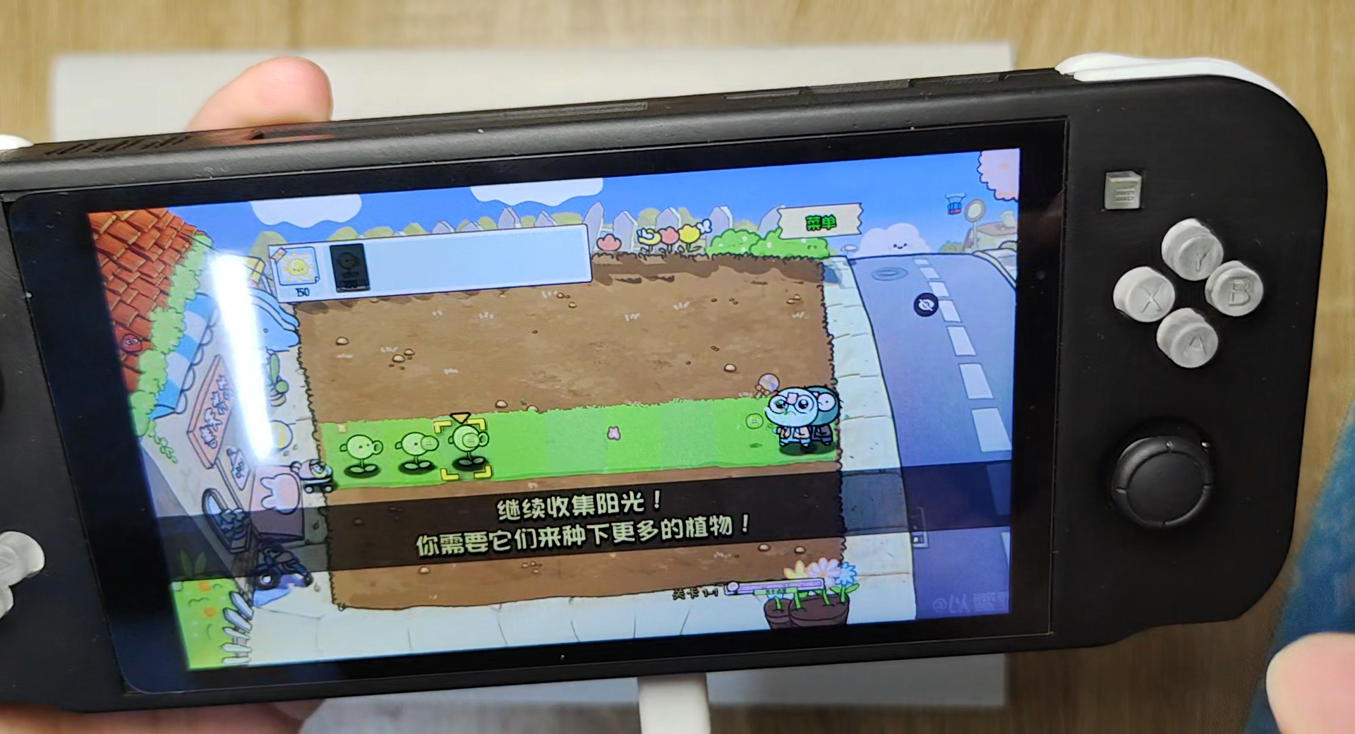
project is a smartphone based on the LCSC Taishanpai Development Board, adapted for Android 11 and Ubuntu 20.04. It features built-in lithium battery management, 4G baseband, 3.1-inch touchscreen, camera, power amplifier, voice input, accelerometer, angular velocity sensor, magnetometer, and touch buttons. It can achieve lithium battery power supply, GNSS positioning, try out motion-sensing games, make calls, send text messages, take photos, videos, play music, and all common Android apps. Smartphones represent the pinnacle of embedded development, yet there are very few open-source smartphones currently available. DIY smartphones are the best project for learning and practicing circuit design, PCB layout, and soldering, enabling customized operating systems and drivers, and developing or modifying application software.
This project involves BGA package soldering, which is quite difficult for beginners. You can first learn about previous versions of this project. Link: [Little Dolphin Mobile Phone] Taishanpai 4G Internet Mini Phone - LCSC Open Source Hardware Platform (oshwhub.com)
The EC20 module consumes a lot of power, and the 4G module has an independent power supply output. The 4G module power supply switch is controlled by the 4G_PWREN_H pin, i.e., GPIO0 PA1. When 4G is not needed, this pin can be set to low level to save power.
The TP5100 lithium battery charging management chip is fragile. If the hardware design is not good, it is easy to burn out. Please strictly refer to its official design manual when designing! 4G
has its own voice output. After testing, the microphone can be used with Taishanpai, but the speaker cannot. If you need to use the function, please solder FPC7 and remove R41 and R42. And pull GPIO0 PA0 high within the device tree.
4. Software debugging
千古长夜丶/TSPiTSPiPhoneV4.1 - Gitee.com.
If you have modified the Taishanpai Android SDK, please revert to the original version.
Copy the binary library file lib/gps.default.so to the device/rockchip/rk356x directory.
Copy the Taishanpai Android SDK to the corresponding Git repository patch. For the corresponding hardware version V4.1, navigate to the corresponding Android SDK
patch/kernel.patch .
Then copy the patch files to the corresponding directories and use the following command:
`patch -p1 -N -d . < corresponding patch file.patch`.
`source build/envsetup.sh && lunch rk3566_tspi-userdebug`.
Compile (virtual machine memory should ideally be ≥16GB; if not, change to -j8).
. (Image shown
). Development stage:
2024-03-27 V1 Initial Design.
2024-04-22 V2 Optimized screen interface layout.
2024-05-28 V3 Added screen backlight circuit IC and optimized screen backlight heat dissipation.
2024-07-12 V4 Added lithium battery charging management, sensors, power amplifier, and touch buttons, and optimized details.
2024-08-01 V4.1 Fixed lithium battery charging circuit and optimized details. This is the first time
project has been publicly released; it is my original work. This project has not won any awards in other competitions.
This project follows the CC BY-NC-SA 4.0 open-source license; unauthorized reproduction and commercial use are prohibited.
1. [Little Dolphin Phone] Taishanpai 4G Internet Mini Phone - LCSC Open Source Hardware Platform (oshwhub.com)
2. Taishanpai 3.1-inch Screen Expansion Board - Integrated Power Supply, Audio, Serial Port, RTC - LCSC Open Source Hardware Platform (oshwhub.com)
3. LCSC Taishanpai Development Board 39Pin_Hub2.0_Ethernet Expansion Board
One-click switching, dual functionality: ESP-Dongle brings you the ultimate experience from wireless network card to USB flash drive.
Project Introduction:
The ESP Dongle is a multi-functional USB device solution developed based on the Espressif ESP32-S3 microcontroller. This project seamlessly integrates the functions of a USB MSC wireless flash drive and a USB wireless network adapter into a single device, switching between these functions via a sliding switch.
In USB MSC wireless flash drive mode, the device acts as a wirelessly accessible USB disk, allowing users to access and manage data on the onboard flash memory or SD card via USB connection. Simultaneously, the device provides a built-in file server via Wi-Fi, supporting file uploads and downloads, thereby improving the flexibility and convenience of data management.
In USB wireless network adapter mode, the device acts as a network adapter, allowing the host to establish a wireless network connection and featuring hot-swapping capability, further enhancing operational flexibility and convenience.
Physical Product Demonstration:
The physical product image
is shown below.
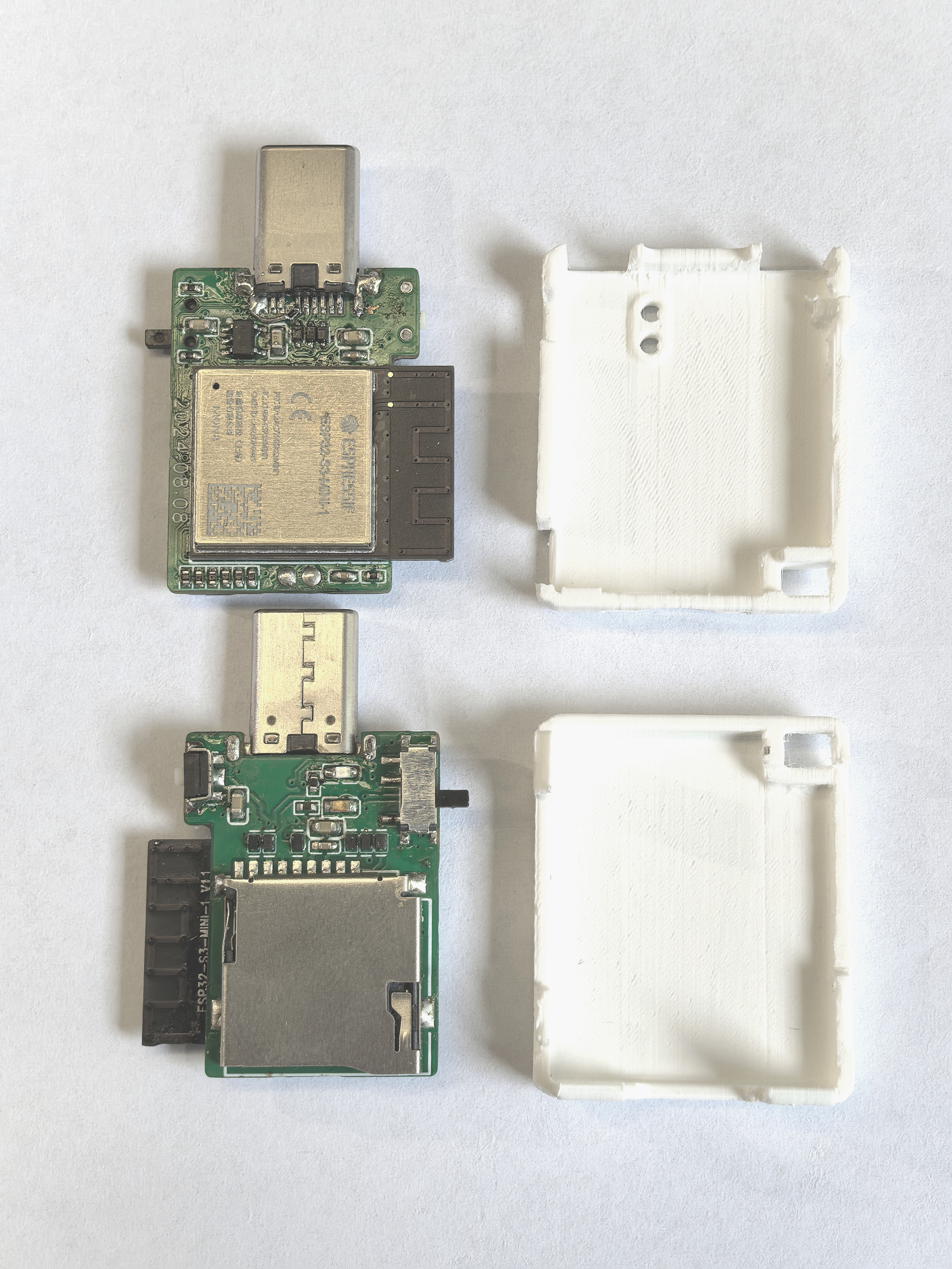
The 3D file of the casing can be downloaded from the attachment!
Video Demonstration:
Building a multi-functional USB Dongle with the ESP32-S3
is not easy, so please like, comment, and subscribe after watching!
Project Related Functions:
The sliding switch allows users to switch between USB MSC wireless flash drive and USB wireless network adapter functions.
In USB MSC wireless network drive mode, ensure the device and ESP32-S3 are on the same local area network. Users can access and manage the SD card content on the ESP32-S3 via a browser by accessing 192.168.4.1.
In USB wireless network adapter mode, the device can be used as a network adapter. Users need to pre-configure the room's Wi-Fi SSID and password. When the device is connected to a computer, the system will automatically connect to the pre-configured Wi-Fi network.
Hardware Description
:
The SD card interface supports 1-wire, 4-wire SDIO mode, and SPI mode. Furthermore, to ensure signal stability, each pin is pulled up with a 10kΩ resistor and uses ESD protection devices to prevent damage from electrostatic discharge.
The HE9073A33M5R low dropout regulator (LDO) chip is used for power supply regulation, stabilizing the input voltage range from 3.3V to 7V and outputting it to 3.3V, ensuring system power supply stability.
The two ends of the slider switch are pulled up and pulled down respectively. The current on/off state of the switch is determined by reading the level status through GPIO4.
The differential signal lines D- and D+ of the USB Type-C interface are directly connected to the USB interface of the ESP32-S3. The D-, D+, and VUSB pins are protected against electrostatic discharge (ESD) to prevent damage to the circuit. Note that the CC pin needs to be pulled down with a 5.1K resistor; otherwise, it will not be recognized by the host.
Hardware Components
: The hardware system consists of the following components:
Main controller: ESP32-S3-MINI-1-N8;
Type-C interface
; SD card slot
; voltage regulator circuit;
slide switch;
tactile switch
; LED indicator
; power option ; powered
via Type-C interface.
Software Description:
Version information:
ESP-IDF
chip
Flash
release/v5.2;
ESP32-S3-MINI-1-N8
8 MB.
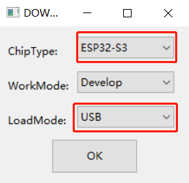
Programming Instructions:
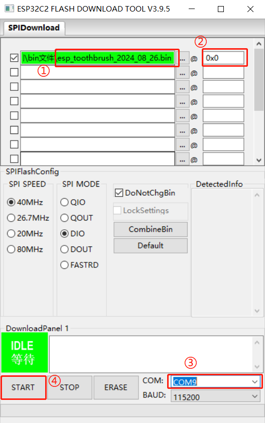
Download the programming software: Espressif Systems official website - Support - Related Downloads - Tools - Flash Download Tool
. After downloading, extract the file and find flash_download_tool_3.9.7.exe. Double-click it. Then select ESP32-S3 and USB, and click OK.
4. Open the software and directly burn the esp_dongle_20240827.bin file from the attachment into address 0x0. The steps are as follows.

User Instructions for ESP-Dongle
Wireless Disk
: After plugging in the device, your phone needs to connect to a Wi-Fi hotspot named "ESP-Wireless-Disk". Then, open your browser and access 192.168.4.1 to transfer files. Network Adapter:
When using the network adapter's function, the firmware (i.e., the bin file) sets the Wi-Fi hotspot username and password to esp_dongle. Therefore, users need to manually create a Wi-Fi hotspot (both username and password must be: esp_dongle). The ESP-Dongle will then automatically connect to this hotspot.
This project is the Cyberry Potter Electromagic Wand, using an STM32 microcontroller as the main control chip. It employs a convolutional neural network for motion recognition and features a modular design with extremely high scalability.
Video Tutorial Link:
Bilibili Video -- Function Demonstration and Introduction
Project Introduction
This project is the Cyberry Potter Electromagic Wand, which uses convolutional neural networks for action recognition and adopts a modular design with high scalability. You can use the files in this project to create a cybernetic wand. If you have sufficient skills, you can also modify the wand's spells (functions). The wand adopts a modular design, with different modules corresponding to different execution functions. You can create new modules and add new functions according to your needs. You can also modify the action of activating spells; you only need to recollect data and train the model.
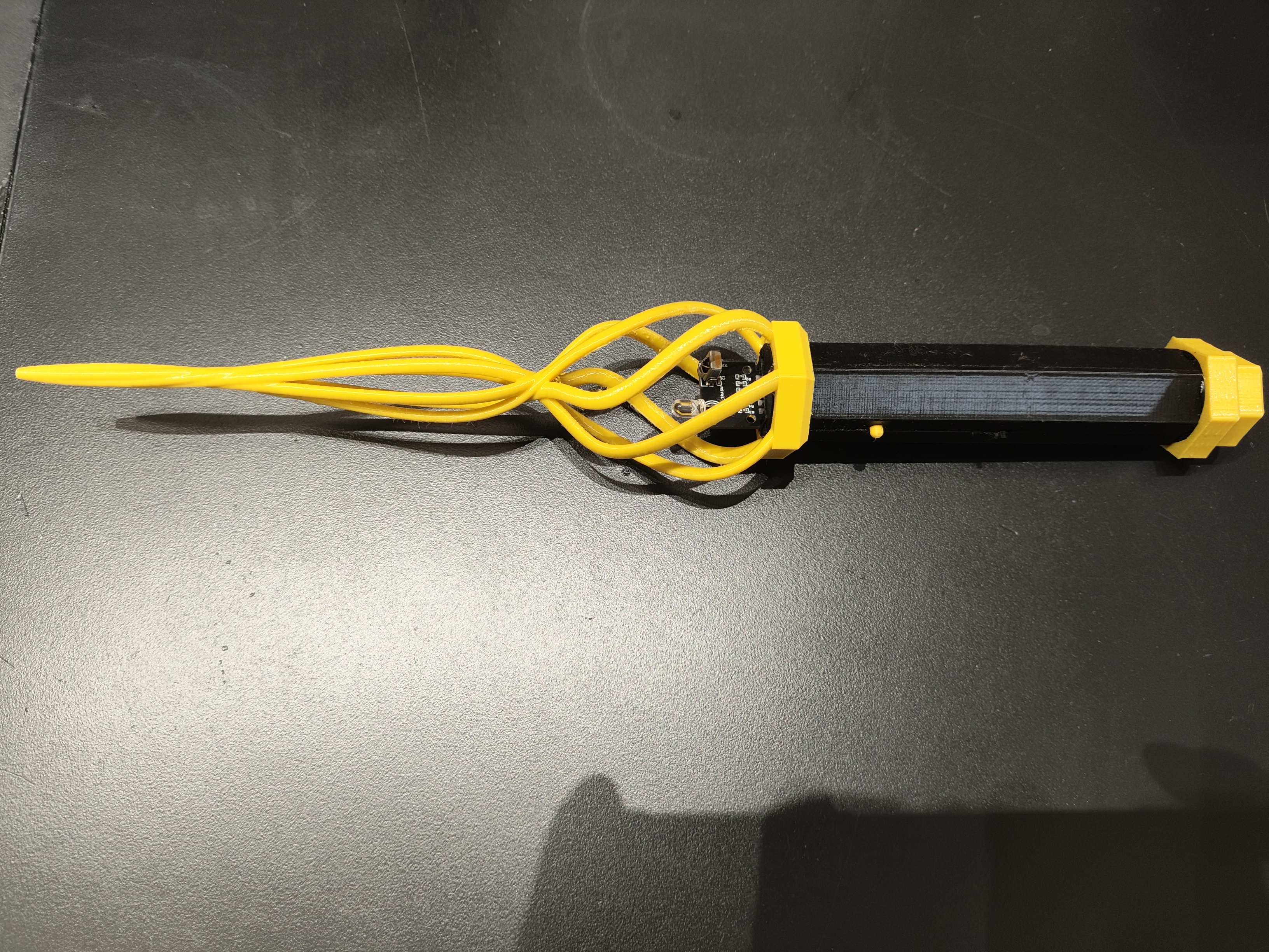
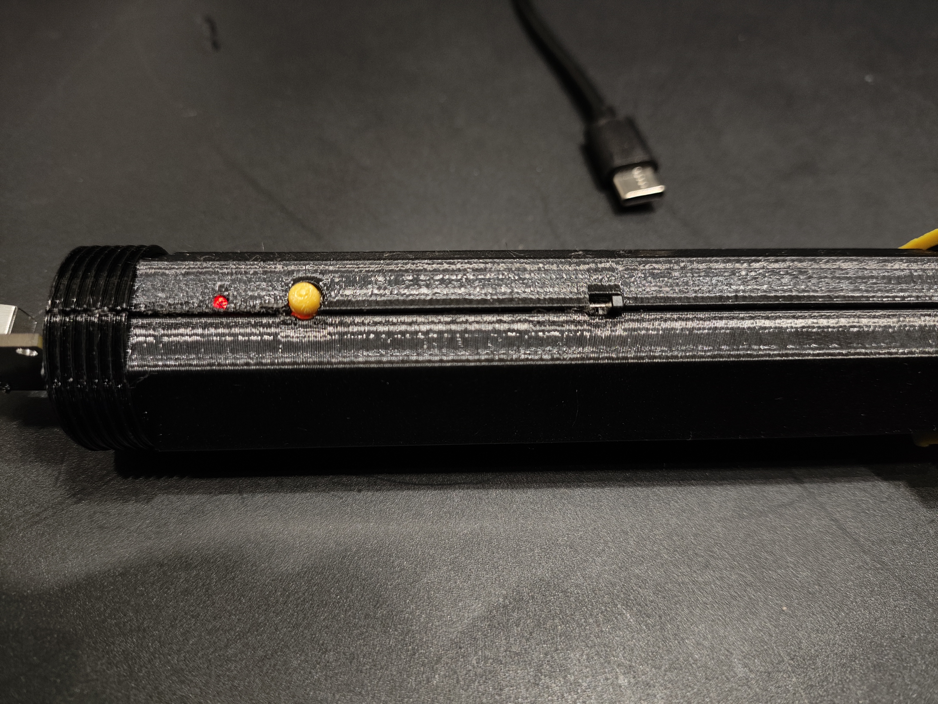
Physical Demonstration
Assembled Status
Disassembly Status
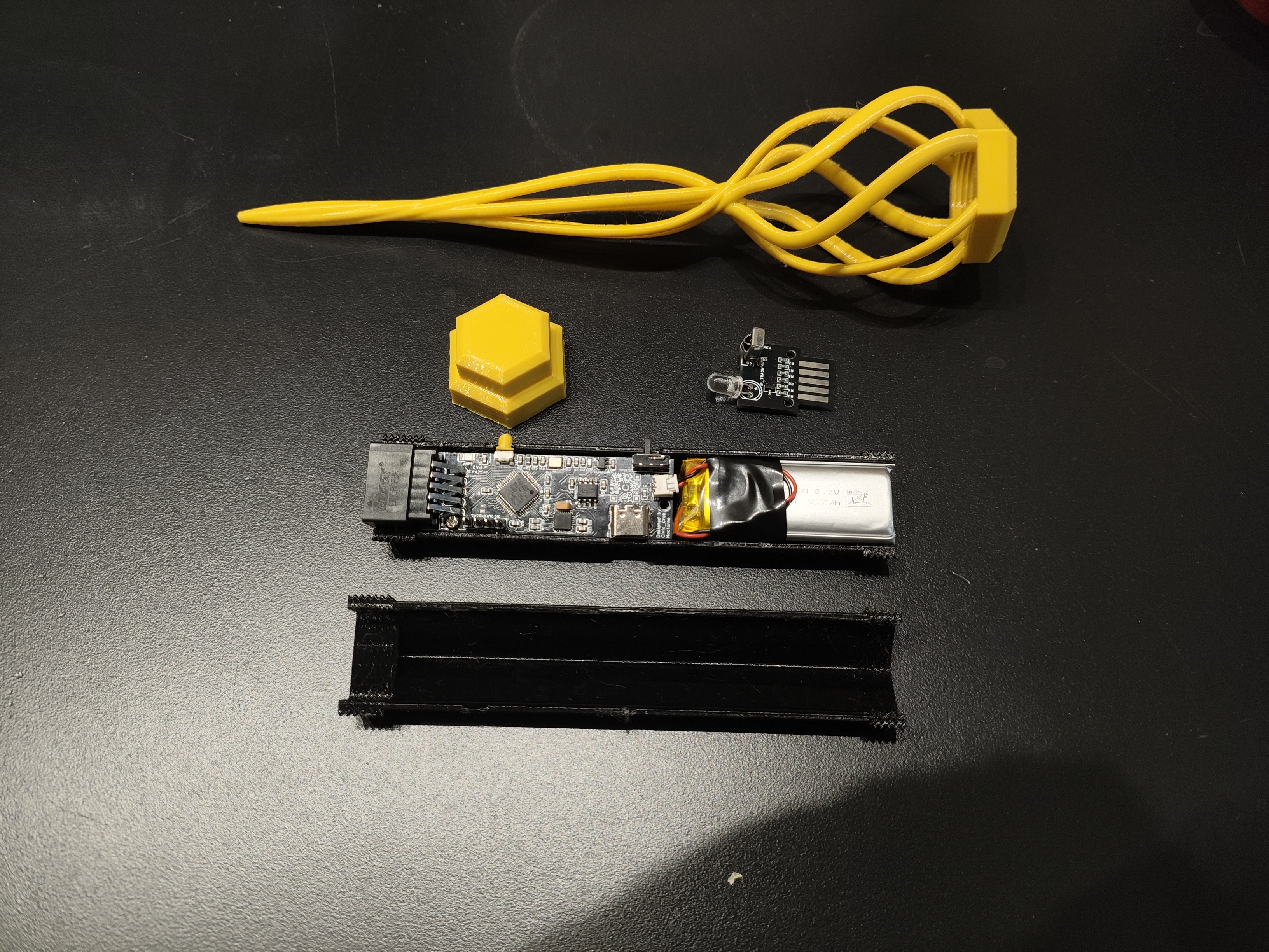
Module Insertion Direction: Front Face Down
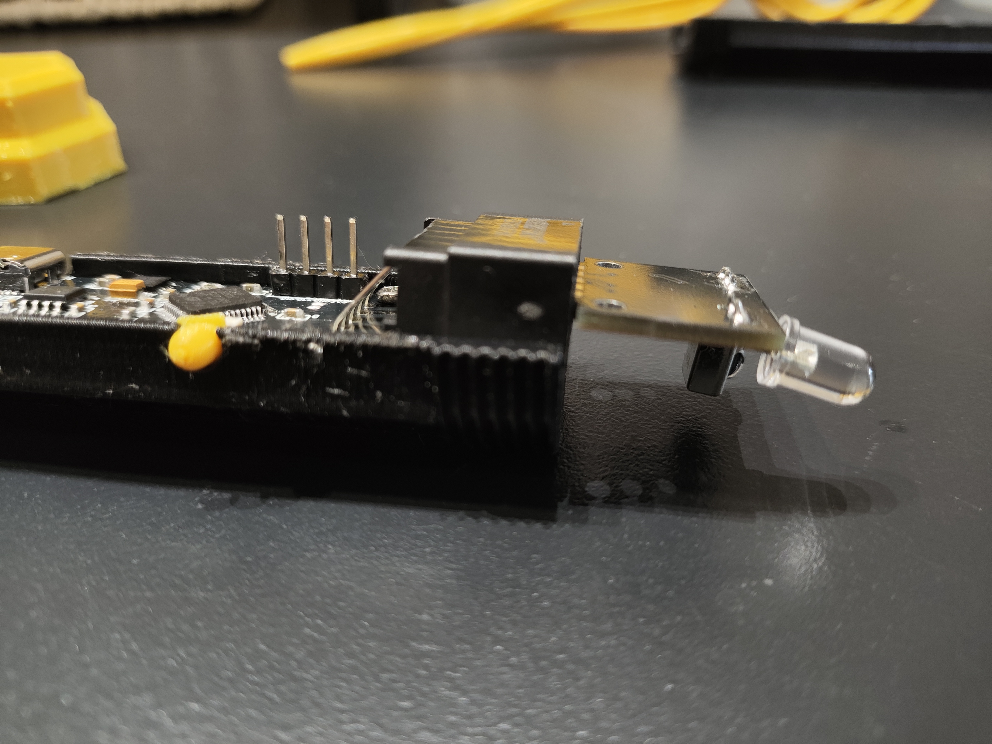
The Type-C port can be used for charging and serial port debugging. The red light is on when charging, and the green light is on when fully charged
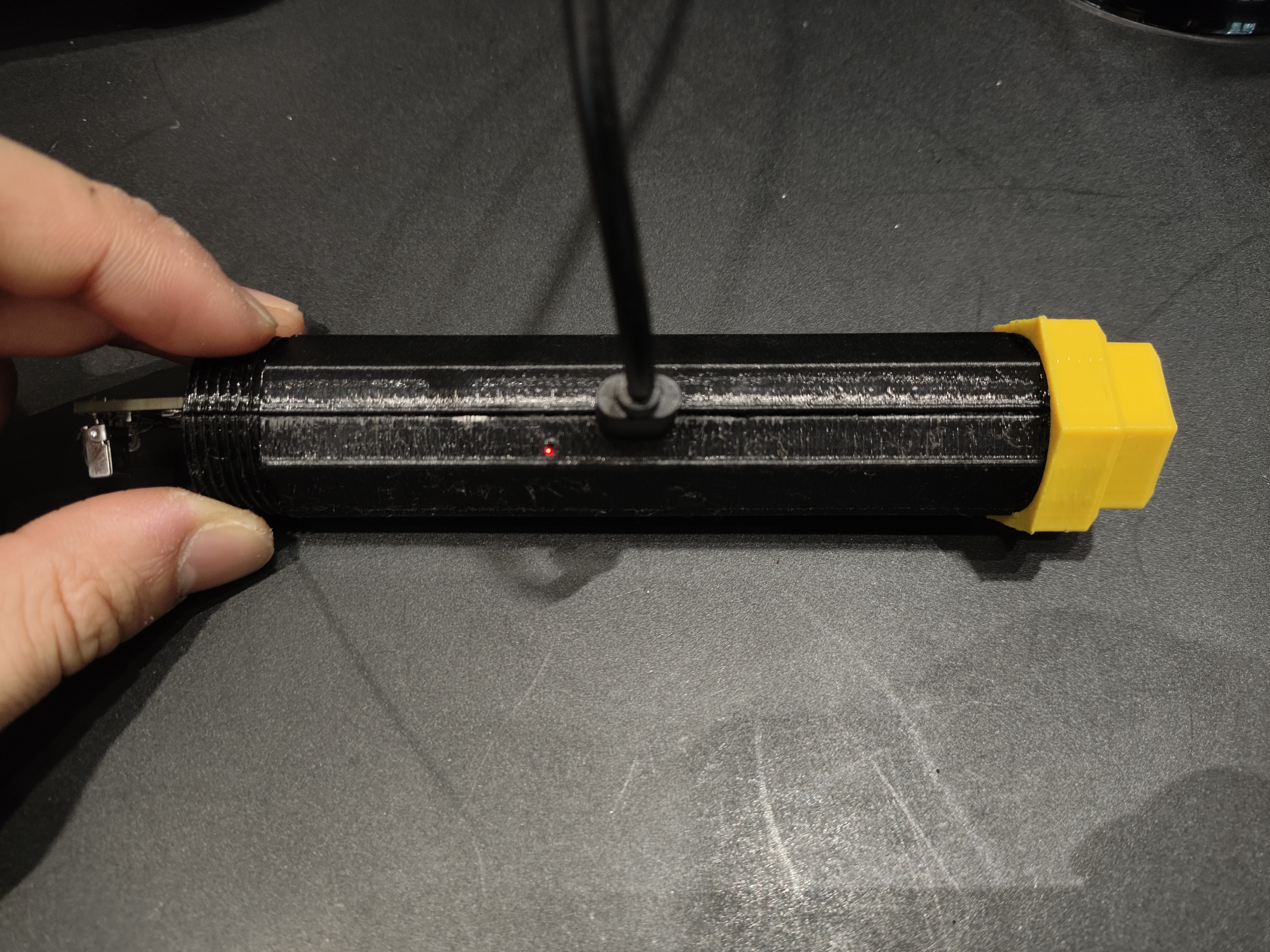
. From left to right: status indicator, interactive button, power switch
Project Function Introduction
After the motherboard is powered on, it will enter mode 0. Press and hold the button for 0.5 seconds and then release to enter mode 1.
Short press and release the button in any mode: Sample the IMU for 1.5 seconds, input the data into the model to obtain the action recognition output. Different modules will execute different functions after obtaining the action recognition result.
When an infrared module is inserted, infrared signals of any protocol can be copied, such as air conditioner and NEC.
Mode 0: After obtaining the action recognition output, the module will send the recorded infrared signal according to the recognized action.
Mode 1: After obtaining the action recognition output, the module will wait and record the infrared signal according to the recognized action.
The operations performed in Mode 0 and Mode 1 can be different depending on the inserted module (code writing is required).
Function of Type-C port: It can be used for serial port debugging and battery charging. When there is a Type-C connection, the device will use Type-C instead of battery power.
Power switch: The power switch is responsible for turning the 3.3V power supply on or off. When the power switch is not turned on, battery charging can proceed normally, but STM32 and gyroscope will not be powered on. Working
button: The button has two control methods: long press and release (release after more than 0.5 seconds) and short press and release (release within 0.5 seconds).
The LED in front of the button is a system status indicator, with five states: 10Hz flashing, 5Hz flashing, 2Hz flashing, constant light, and off.
(Hardware Description)
This design uses the STM32F103CBT6 as the main control chip. Neural network inference and main functions run on the STM32. Currently, it can recognize 12 types of movements.
Data can be collected on a computer and the model can be retrained to add new movements or adapt to individual waving habits.
The neural network model occupies less than 8kb of memory, saving significant resources.
Inference time is around 100 milliseconds; inference occurs immediately after sampling, with no noticeable delay.
This design uses the MPU6050 as the motion information acquisition chip
. A red... The external module and RF module have recording and transmission/reception functions.
Recording by the infrared and RF modules does not require decoding, meaning any signal can be recorded (except encrypted signals).
Infrared and RF signals are stored through an external W25Q16 memory, which retains the data even when power is off.
Module detection uses an ADC to sample the voltage values of the voltage divider resistors on the module to identify it.
The ADC uses variance checking to detect if any modules have been inserted.
The
complete wand code and shell are available on GitHub.
The software code is located in the Software directory, containing a Keil project. The model training scripts, data collection scripts, and spell action cards are located in the ./Software/CNN directory.
Please refer to the readme document in GitHub for development environment configuration.
You can also download the 3D shell files and spell cards below.
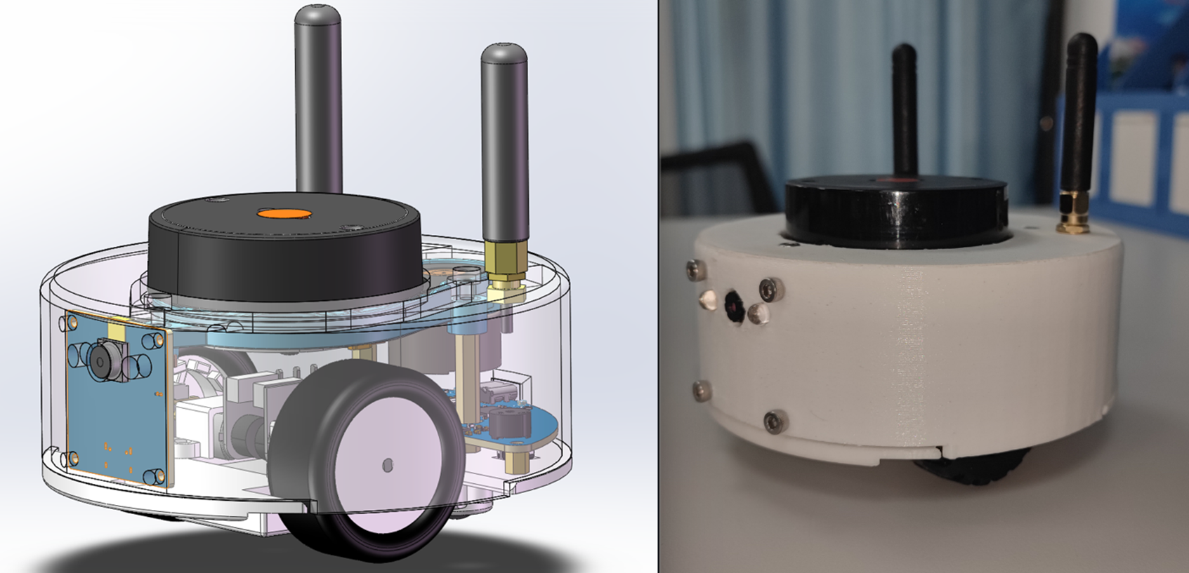
This is a smart car, only the size of a palm, running the ROS1 robot system. It can perform basic LiDAR 2D mapping and navigation functions, and can be controlled with the assistance of a mobile APP. It also has extended functions such as radar tracking, visual recognition and tracking.
Project Description:
The Idea's Origin
In 2021, the Bilibili influencer "Zhihuijun" created a bicycle. I noticed he used the ROS system, enabling 2D map creation, path planning, and image recognition.
Zhejiang University's Fast-Lab also used the ROS robot system for its flying machine, performing various intelligent operations.
I initially thought ROS was extremely complex and difficult to understand. However, after some study, I discovered that ROS is like a slightly more advanced version of "Lego bricks." Experts encapsulate the code into various "function packages," much like Arduino's "libraries." I don't need to write navigation or mapping algorithms; I just need to download the corresponding code package from the official website, modify some parameters, and connect these packages to perform seemingly sophisticated operations like mapping and navigation.
Of course, there are still some differences between theory and practice.
To put this into practice, I considered buying a ready-made bicycle to learn ROS, but found the price too high… Even basic mapping functionality would cost over a thousand yuan. In the end, I still spent over 2400 yuan to buy one and studied it for a month.
After completing the basic learning, I found that the toy car was basically useless and was gathering dust on the side.

So, I had another idea!
I wondered if I could replicate what I had learned in the past month? Could I also make a low-cost and relatively compact smart car?
With this idea in mind, I started this project. In the end, the project was about the size of a palm, and the cost was controlled at around 260 yuan. The appearance was made more exquisite, so the shell had to be complete.
The
open-source license
is GPL 3.0.
This is the GNU General Public License. If a product under the GPL license is used in a project, then the project must also adopt the GPL license, which means it must be open source and free.
The starting point of GPL is the open source and free use of code, and the open source and free use of reference, modification, and derivative code, but it does not allow modified and derived code to be released and sold as closed-source commercial software.
The most significant characteristics of GPL are "viral distribution" and "disallowing closed-source commercial distribution". Linux, which we are familiar with, uses the GPL license.
Project-related functions:
main function completion status (7)
The car can be manually controlled by the mobile APP (completed)
Specific function: Two remote controls can be used to control the front and back and left and right independently, which has a better control effect and can also provide some simple data feedback.
Use LiDAR for 2D mapping. Use RVIZ visualization tool to display (completed)
Specific function: Manually control the car to move and explore unknown locations, use LiDAR to draw the surrounding contours, and draw a 2D plane map.
Use LiDAR for navigation and use RVIZ visualization tool to display (completed)
Specific function: After running, the map drawn by the previous function will be opened. Mark any point in rviz, and the car will automatically plan the route and drive to the corresponding point. If an obstacle suddenly appears in the middle, it will automatically detour.
Use radar to track the target (completed)
Specific function: After running the function package, it will automatically follow the nearest object. It is still a bit useless and can only be used in relatively wide places, otherwise it is easy to lose track.
Use camera for HSV color block tracking (completed)
Specific function: This can only track color blocks. The main function is to convert the image to HSV. Each color has a different HSV value. The color block area is determined by the lookup value, and then the coordinates are output. Finally,
the target feature is identified by the camera based on the coordinates. (Completed)
The find_object_2d function package is used. After running, the screen and the generated feature points appear. The corresponding object is selected and identified. It can be
charged and discharged via USB. (Completed)
It can be charged via USB interface. Otherwise, it is more troublesome to remove the battery.
Additional functions are discarded. (3)
The mobile phone displays the mapping results and video screen. (Discarded)
Reason: The URL can only be read by one device at a time. Multiple forwarding will cause the screen to be severely laggy. (No solution found)
Simple obstacle avoidance is performed by relying on its own computing power without using a computer. (Discarded)
Reason: The data packet structure of the newly compatible X2 radar cannot be found and cannot be intercepted. It is read and forwarded directly to the host computer. This is more universal. One program can be compatible with multiple radars without switching programs.
RRT autonomous exploration mapping. (Discarded)
Reason: The exploration effect is poor. (No solution found)
Project attributes
This project is the first time it has been made public. It is my original project.
The chassis code framework is modified from the Liguanxi-UAV aircraft code, and the coding style is the same as the previous project.
Most of the knowledge used in this project was obtained from the Internet, and most of it is open and free information. The links are as follows:
CSDN Forum
JoystickView: Creating a Custom Game Controller Android Library - CSDN Blog
Implementing LiDAR-Based Target Following in ROS_Multi-Target Tracking Function Package in ROS - CSDN Blog
CMOS Debugging Experience_ov2640 Driver Initialization Imaging Blur - CSDN Blog
ROS-Machine Vision: Specific Object Recognition (find_object_2d Package)_Object Detection and Tracking ROS Function Package - CSDN Blog
ESP32 Arduino Learning (Part 1). Setting a Static IP_esp32 Static IP - CSDN Blog
ROS Publish and Subscribe to Images_ROS Subscribe to Images - CSDN Blog
Raspberry Pi Learning: Learning OpenCV + Using OpenCV to Get Raspberry Pi Mjpg Camera Video Stream_Raspberry Pi Video Stream - CSDN Blog
ESP32-CAM on Web Taking pictures and displaying images on a server - How to take pictures with ESP32Cam - CSDN Blog;
ESP32Cam camera + host computer OpenCV face recognition - OpenCV.js ESP32-Cam - CSDN Blog;
Mapping a serial port to a TCP server port using socat under Linux - Socat serial port - CSDN Blog;
Detecting seven colors in an image with OpenCV, distinguishing colors and corresponding positions - Color location in an image (CBCC) - CSDN Blog;
Mutual conversion between RGB and HSL colors - HSL to RGB - CSDN Blog
; [OpenCV] Common HSV color upper and lower limits - Threshold ranges for red, yellow, blue, and green colors - CSDN Blog;
Usage of HSV color space table and cv2.inRange() - HSV range - CSDN Blog;
OpenCV - Python extraction of laser images using corresponding HSV values - HSV hue extraction steps - CSDN Blog;
OpenCV tutorial: CV2 module - Image processing, HSV, hue, and brightness adjustment - cv2 hsv - CSDN Blog
Python: Color Block Detection, Tracking, and Printing Center Coordinates_Python Get Geolocation Color Block Center Point - CSDN Blog
Solidworks Export Two-DOF Servo Platform URDF for Gazebo Simulation_SW2022 Import Gazebo - CSDN Blog
Move Base Parameters and Global Planner, Local Planner Settings_MoveBase Local Cost Map Settings - CSDN Blog
DWA Parameter Adjustment 2_DWA Parameter Tuning - CSDN Blog
Github
https://github.com/YDLIDAR/YDLidar-SDK/blob/master/doc/howto/how_to_build_and_install.md
https://github.com/rauwuckl/ros_simple_follower
GitHub - ros/solidworks_urdf_exporter: SolidWorks to URDF Exporter
Bilibili Video Website
Robot Operating System ROS Quick Start Tutorial_Bilibili_bilibili
LCSC EDA Drawing 2.4GHz RF Double-Layer Board Fabrication - NanoVNA Debugging and Impedance Matching_Bilibili_bilibili
Books
"ROS Educational Robot Training Tutorial"
"Linux from Beginner to Expert 2nd Edition"
Project Progress
Overall project progress, application for project consumable costs is required!
January 15, 2024 - February 3, 2024: Project initiation and supplementation of basic knowledge in ROS and network communication.
February 4, 2024 - February 8, 2024: Building models using Soliworks, confirming the shape and component structure.
February 9, 2024 - February 12, 2024: Creating a new virtual machine to set up the ROS system and related compilation environment.
February 12, 2024 - February 17, 2024: Building the basic prototype of ESP32 code, peripheral code, and mobile APP remote control (first version, using the Arduino code editor and the DianDeng Technology APP).
February 18, 2024 - February 18, 2024: Determining specific component models, specific implementation direction, and establishing a JLCPCB project.
February 18, 2024 - February 23, 2024: Completing the first version of the PCB circuit.
February 23, 2024 - April 1, 2024 Due to work commitments, project development was temporarily suspended for a period of time.
April 1st - April 4th, 2024: Verified the feasibility of the UDP/TCP communication link; radar data could be observed using RVIZ.
April 5th - April 7th, 2024: Overturned the first version of the PCB and baseboard code design and redesigned the second version.
April 8th - April 11th, 2024: Modified the model to adapt to the new chassis auxiliary wheels.
April 12th - April 20th, 2024: Due to work commitments, project development was temporarily suspended for a period of time.
April 20th - April 22nd, 2024: Build the basic prototype of the ESP32 code, peripheral code, and mobile APP remote control (second version, using the ESPressif code editor, writing the Android APP from source code).
April 22nd - April 24th, 2024: Learned Android Studio to write a remote control APP program using Java
. April 24th - May 1, 2024: Completed the second version of the PCB, and carried out PCB and SMT production (JLCPCB reimbursed 1047.48 RMB). SMT costs were mostly for the PCB itself, not the components.
May 1 - May 3, 2024: Model adjustments, added antennas, and modified the camera.
May 4 - May 5, 2024: Successfully configured the function package and conducted drawing tests.
May 5 - May 12, 2024: Project development was temporarily suspended due to work reasons.
May 13 - May 18, 2024: PCB arrived; tested basic code; performed sensor reading and conversion on the chassis; and checked the circuit.
May 18 - May 22, 2024: PCB functionality malfunctioned; the antenna circuit was unusable. Supplemented RF circuit knowledge and high-speed circuit design specifications; redesigned the third version of the PCB and prototyped it.
May 23 - May 25, 2024 While waiting for the new PCB, joint debugging of the ROS system and chassis system was conducted to resolve several issues such as automatic reconnection and abnormal data transmission.
May 26, 2024 - May 26, 2024: The third version of the PCB arrived, and soldering and debugging were performed.
May 26, 2024 - May 28, 2024: Schematic diagramming was performed, but the connection remained unstable, and the WiFi signal was poor. Initial assessment indicated that the filtering circuit was not properly configured. Relevant knowledge was studied, and a network vector analyzer was purchased for adjustments.
May 28, 2024 - June 1, 2024: During schematic diagramming, it was discovered that the two auxiliary wheels caused the vehicle to sway with the radar rotation, which was structurally unreasonable. After referencing numerous differential cars, the chassis was modified to a three-wheeled design (two drive wheels and one auxiliary wheel), the battery was lowered, and the structure was simplified.
June 2, 2024 - June 2, 2024 Since the network vector analyzer hadn't arrived yet, I first performed simple calculations. Using a general-purpose network, the signal improved significantly. I then created a complete network map and saved it.
June 3, 2024 - June 3, 2024: Improved open-source documentation.
June 4, 2024 - June 5, 2024: Used a vector network analyzer with SmithV4.1 to adjust antenna circuit parameters, ultimately controlling the VSWR within ±1.3, and modified the WiFi channel.
June 5, 2024 - June 6, 2024: Optimized PCB routing, learned corresponding routing rules, and tried to comply with specifications.
June 6, 2024 - June 7, 2024: Switched all communication to TCP, modified positioning parameters, and significantly improved positioning performance.
June 8, 2024 - June 8, 2024: Created a BOM (Bill of Materials), a communication link diagram, and improved some open-source projects.
June 9, 2024 - June 10, 2024: Debugging navigation function, continuously adjusting cost map and car parameters, assembling the new vehicle body, and filming demonstration videos.
June 11, 2024 - June 15, 2024: PCB arrival, soldering verification.
June 16, 2024 - June 17, 2024: Optimized the car chassis, added motion closed-loop, and debugged the anonymous host computer.
June 18, 2024 - June 18, 2024: Improved open-source documentation.
June 19, 2024 - June 25, 2024: Verified the camera solution, using ESP32S3CAM to verify the communication link with ROS.
June 25, 2024 - June 30, 2024: Designed the first version of the camera circuit and PCB, and prototyped it.
July 1, 2024 - July 5, 2024: Project development was temporarily suspended due to work reasons.
July 6, 2024 - July 7, 2024: The camera PCB arrived; soldering and debugging were performed to achieve basic object feature recognition and detection.
July 7, 2024 - July 8, 2024 The high-speed circuit design had issues; the high-speed lines were too close together, causing coupling and resulting in stuttering and flickering purple or green interference lines. After supplementing relevant knowledge, the high-speed circuit was redrawn, adding GND shielding, increasing the distance between high-speed lines, shortening their length as much as possible, and inserting a GND wire in the middle
. (July 13th - July 14th, 2024: Second version of the camera PCB arrived and was soldered; the effect was quite good, achieving around 15 frames per second on VGA, appearing relatively smooth to the naked eye.) (
July 14th - July 18th, 2024: Radar tracking and visual tracking functionality were added. During debugging, some issues were found with the odometer; it was inaccurate and not precise when controlling the chassis. Because a fixed PWM conversion was used, the speed varied depending on the battery voltage, and the car could not travel in a straight line. Therefore, PID control was introduced to correct the odometer and IMU.) (
July 19th - July 22nd, 2024:) Modified the calibration of the odometer, changed the two-wheel speed of the car to PID control, tuned the PID parameters, and optimized the operation process
. (July 22, 2024 - July 23, 2024) Debugged radar tracking. Due to the instability of remote radar data, the tracking effect was not ideal, and the visual data was also unstable. Pinging the IP address revealed very high latency. Adjusting the network connection to rely on the router resulted in even higher latency, so the original connection had to be reverted.
(July 24, 2024) Achieved compatibility with the X2 radar. The data refresh rate was found to be faster but more unstable, with wall distortion during rotation, but it was still barely usable. The LD14 refresh rate was slow but relatively stable.
(July 25, 2024) Modified the outer shell and re-prototyped it. Modified the code to make it slightly cleaner, and then jointly debugged the vision module. (
July 26, 2024 - August 4, 2024) Project development was temporarily suspended due to work reasons. (
August 5, 2024 - August 6, 2024) When using radar follow, the radar intersection point kept fluctuating between 0 and 6.28, causing tracking failure. The TF tree was adjusted to correct the radar direction. The motion control section of the follow function package's internal code was modified to achieve basic radar follow.
(August 6th - August 7th, 2024) The visual follow function in the follow function package was too complex to understand. A custom function package was written to supplement visual knowledge, detect HSVs within a specific range, draw the color range, output coordinates, and bind to chassis speed to achieve basic color block tracking.
(August 8th - August 25th, 2024) Further study of ROS cost maps and path planning principles was conducted, and motion and navigation parameters were adjusted.
(August 8th - August 24th, 2024) Knowledge of video shooting was supplemented, including script writing, video shooting, and video editing. (
August 24th - August 26th, 2024) First, let me clarify that my knowledge is still limited, and
this project
aims to learn relevant knowledge during the construction process. This is my first time designing a relatively dense circuit, so please point out any errors in the comments section. Regarding the main
control chip
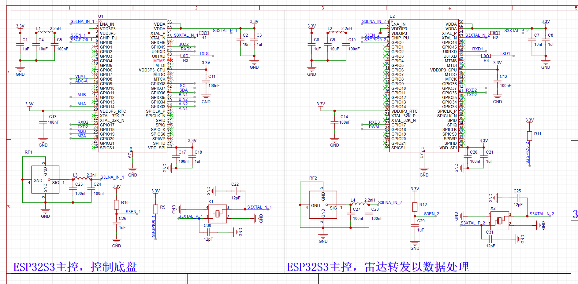
, generally speaking, robot systems like ROS need to run on microcomputers such as Raspberry Pi. However, I wanted to complete this project at the lowest possible cost, so I moved the computer running the ROS system from the onboard unit to a host computer, connecting it to the car via WiFi, thus saving the need for a microcomputer.
However! Radar data is transmitted approximately every 1ms, and one ESP32 is clearly insufficient! Therefore, I chose to use two ESP32s as the main controller.
One is dedicated to forwarding radar data,
and the other is used for motion control and reading sensor data.
A similar structure has been made using ROS, but it is relatively large and has lower circuit integration.
The
ESP32 antenna section is quite sophisticated. Since it involves high-speed circuits,
the first step is impedance matching. According to Espressif's hardware design guidelines, the RF section needs to be impedance matched


 Hardware Design
  Power Supply:
 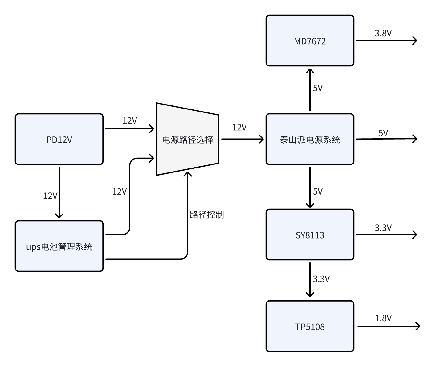 USB Expansion:
 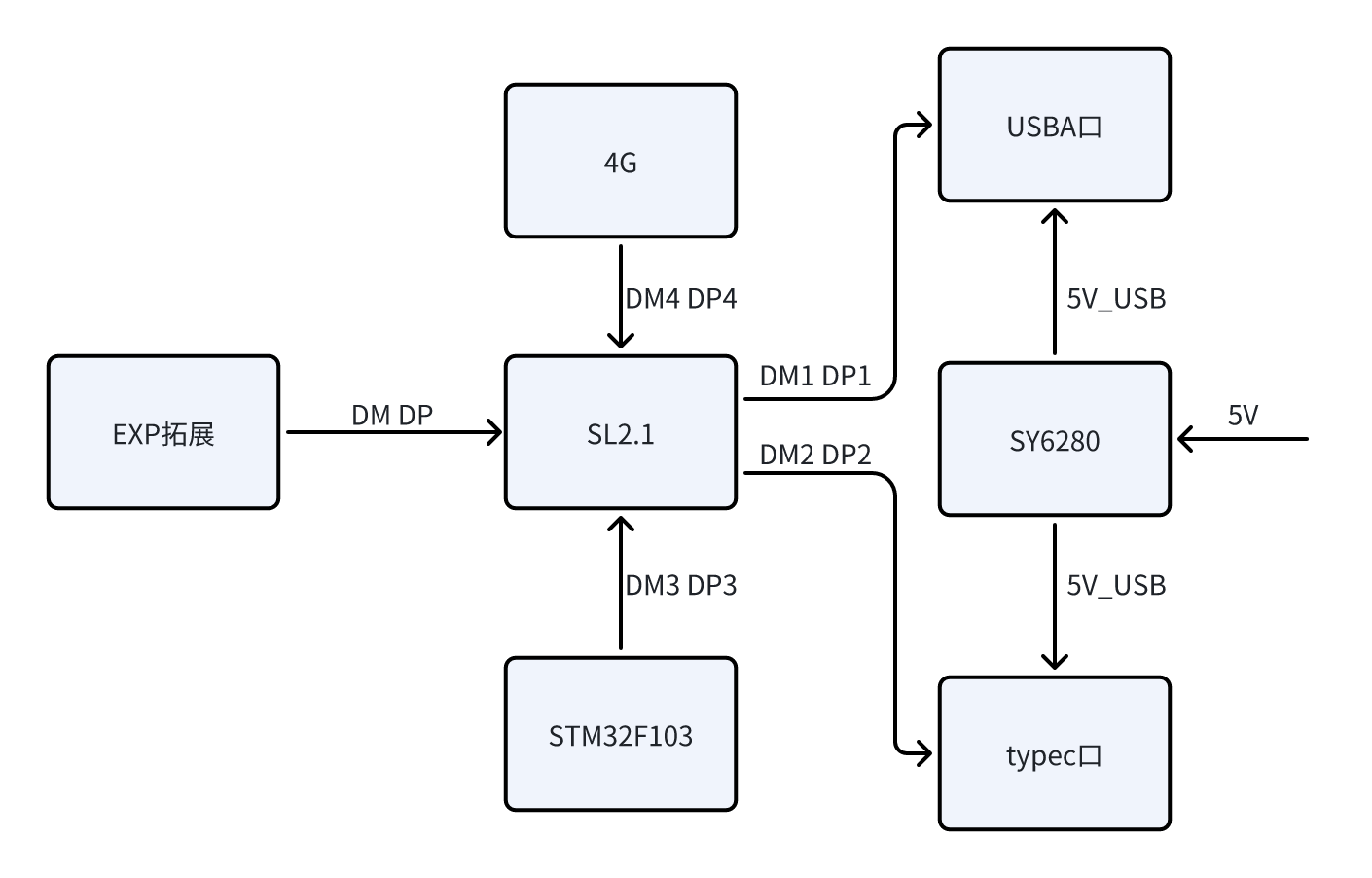 4G:
4G: 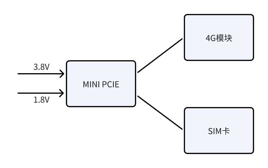 Functional Peripherals:
 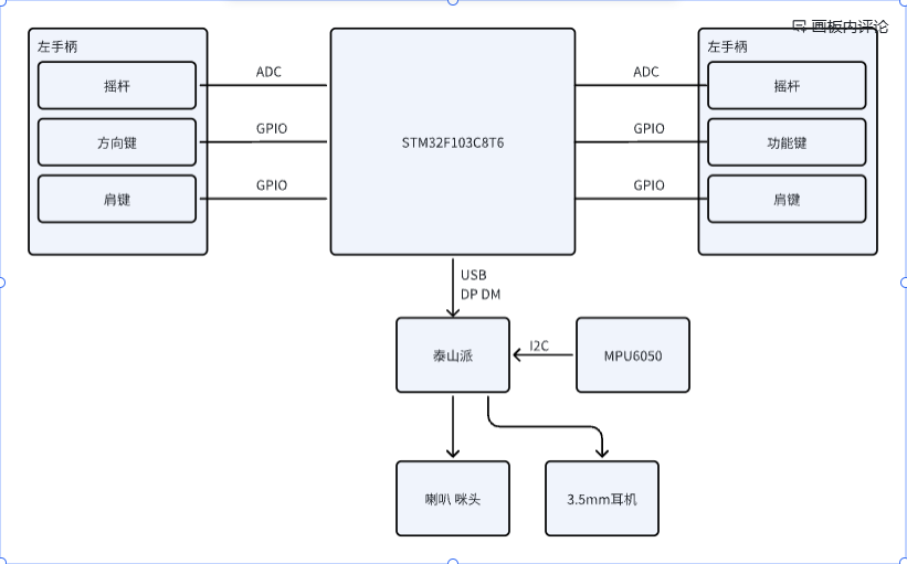 Software Design
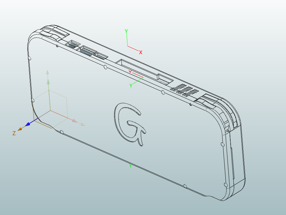
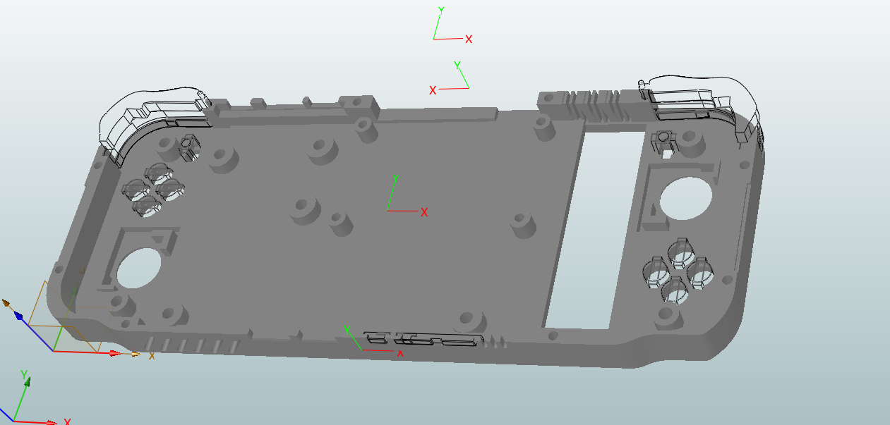
 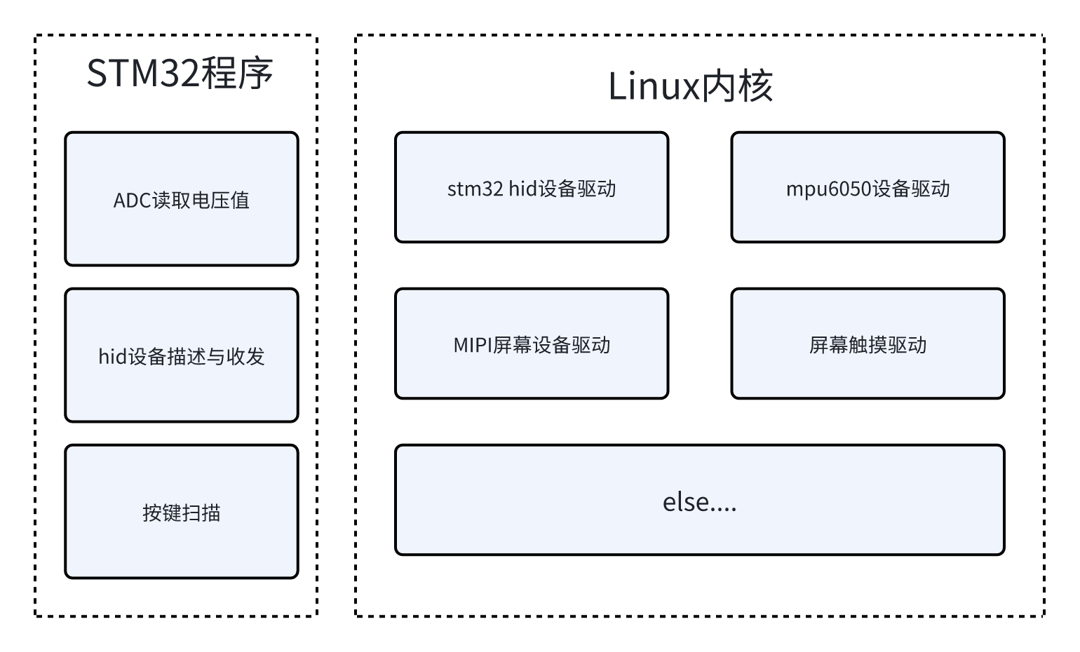 Shell Design:
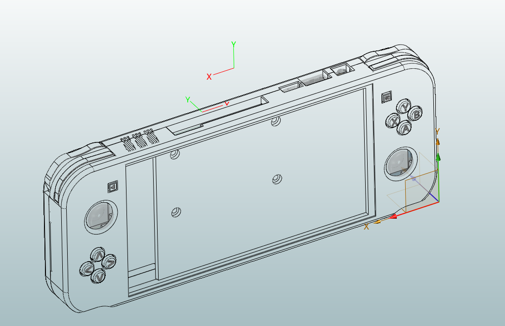
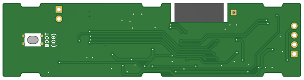
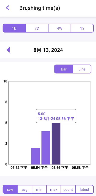
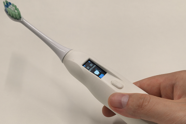 [Image 19] [Image 10] [Image 11] [Image 12] [Image 11] [Image 12] [Image 13] [Image 14] [Image 15] [Image 16] [Image 17] [Image 18] [ Image 19] [Image 19] [Image 12] [Image 19] [Image 11] [Image 12] [Image 19] [Image 11] [Image 12] [Image 13] [Image 14] [Image 15] [Image 16] [Image 17] [Image 18] [Image 19] [Image 19] [Image 11] [Image 19] [Image 12] [Image 19] [Image 11] [Image 12] [Image 19] [Image ESP RainMaker Interface ESP RainMaker is a lightweight IoT cloud computing software deeply integrated with Amazon Web Services' serverless architecture. Based on this serverless architecture, ESP RainMaker offers significant flexibility in data storage and transmission capabilities, dynamically allocating tasks to cloud servers based on actual data traffic, effectively reducing the pressure on the cloud for data storage. For more information about ESP RainMaker, please refer to ESP RainMaker. Using ESP RainMaker, you can achieve the following interface effects: The following are the low battery warning pop-up and main page effects created using RainMaker. The following is the brushing time recording information. The following is the ESP Toothbrush control interface. Video Demonstration ESP-Toothbrush | DIY an ESP32-C2 Smart Electric Toothbrush Making this wasn't easy, so please watch, like, and share! Project Function Description Press and hold the button on the toothbrush to turn it on or off. The device features a 0.96-inch LCD screen with display capabilities and supports various display animations. The device offers four different brushing modes, selectable by double-clicking the button on the brushing interface. Once connected to the internet, the ESP-ToothBrush's brushing mode, duration, and device name can be controlled via ESP RainMaker. The ESP-ToothBrush also synchronizes with the current time. Battery information is uploaded to the ESP RainMaker app; a low battery warning will appear when the battery level drops below 20%. After brushing, the time is recorded in ESP RainMaker, and brushing time and duration data are compiled for one month. The hardware circuit design utilizes a TP4056 chip for battery management, enabling charging while preventing overcharging and over-discharging, and providing reverse connection protection. The CHRG pin of the charging chip is pulled up by a 10K resistor. When the battery is charging, the CHRG pin is low; otherwise, it is high. The CHRG pin is connected to GPIO5 of the ESP32-C2 chip, and the battery charging status can be identified by detecting the level of this pin. Since the maximum range of the ESP32-C2 ADC is 0-3.3V, while the voltage of an 18350 lithium battery can reach up to 4.2V, exceeding 3.3V, two equal-value resistors are used to divide the battery voltage. The battery voltage is then obtained through the ESP32-C2 ADC (GPIO4 corresponds to channel 4). Multiplying the measured voltage value by 2 gives the actual battery voltage, thus enabling battery level monitoring. The HE9073A33M5R LDO chip, with a wide input voltage range, is used for voltage regulation to stabilize the lithium battery voltage to 3.3V, powering the chip and other peripherals. The TC118S DC motor driver chip drives the ultrasonic vibration motor, offering advantages such as low power consumption and low cost. A passive buzzer provides audible alerts. The CP2102N USB-to-UART chip facilitates programming and debugging via the USB Type-C port. Power Options: The ESP-ToothBrush can be powered in either of the following ways: 18350 lithium battery (default power supply, recommended); or via the ESP32-C2's USB port, simultaneously charging the 18350 lithium battery. Software Version Information: ESP-IDF RainMaker chip Flash release/v5.2 1.3.0 ESP32-C2 (ESP8684-MINI-1) 4 MB. Program Download : Download the program from Espressif Systems' official website - Support - Related Downloads - Tools - Flash Download Tool . After downloading, extract the files and find flash_download_tool_3.9.7.exe. Double-click it. Then select ESP32-C2. Open the software and directly burn the esp_toothbrush_2024_08_26.bin file from the attachment into address 0x0. The steps are as follows. Additional Bill of Materials (BOM ) : 3.7V SL18350 Flat Head 850 mAh Lithium Battery, 0.96-inch TFT LCD Ultrasonic Electric Toothbrush Motor, Magnetic Connector, Spring Pin Male/Female Socket, Gold-plated Charging Contacts, Pogo Pin Probe, Pogo Pin Surface Mount, TC118S SOP-8 Single Channel DC Motor Driver IC Chip, FFC/FPC Connector, 0.5MM Bottom Connector Vertical TYPE-C Female Adapter Board, 14P to 2.54 5P Straight-Through Circuit Board, Compatible with Fupai Electric Toothbrush Head Replacement, Universal Revision Notes. Version Revision Notes V1.1 : Added lithium battery overcharge and over-discharge protection circuit.


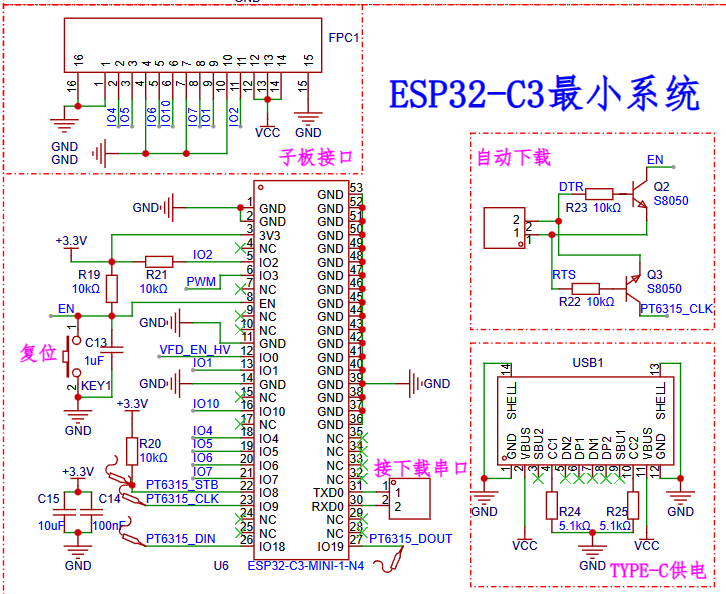 1. Using the ESP32-C3-MINI1 module, its price and pin count are suitable for this project, its performance is stronger than the ESP8266, and I am more familiar with it.
 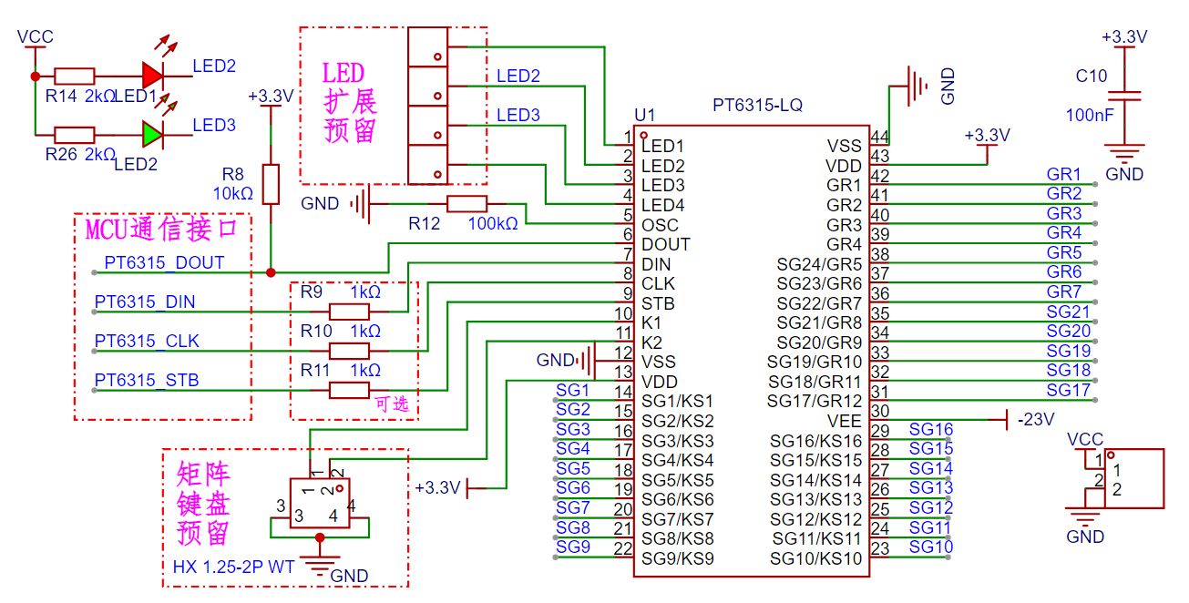 This is the VFD driver chip PT6315.
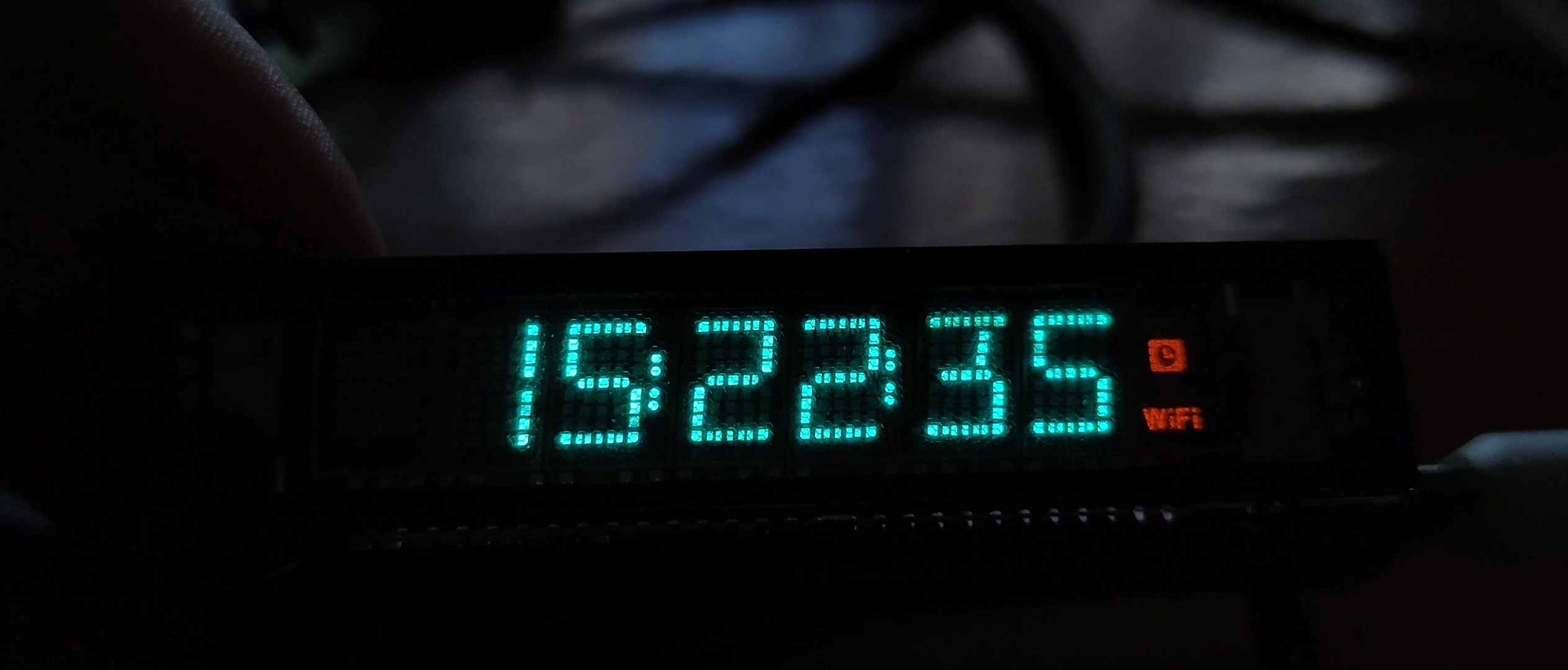
  The PT6315 drives the VFD in a negative voltage manner, therefore it requires a -20V to -28V DC negative voltage.
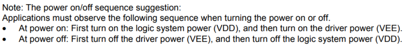
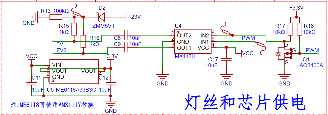 The VFD filament requires AC heating.


 V4 version demonstration video [Bilibili] I made a smartphone!!! Meeting daily needs?
  Motion-sensing game demo
 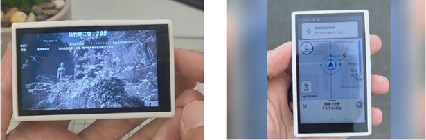 (a) Photography (b) Navigation and positioning
 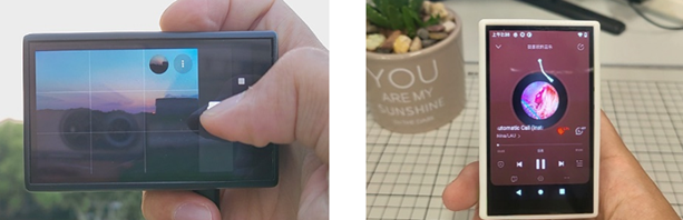 (c) Video playback (d) Music playback
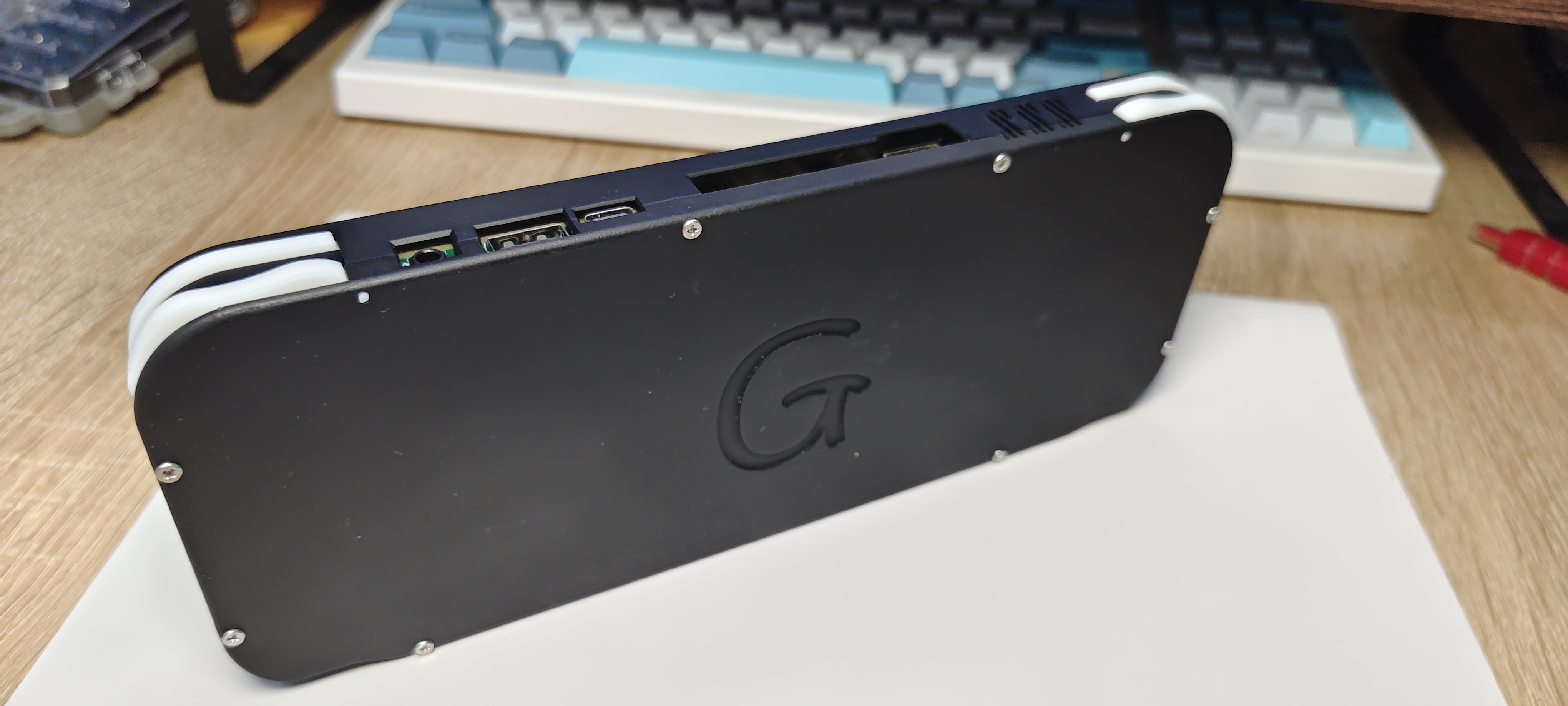
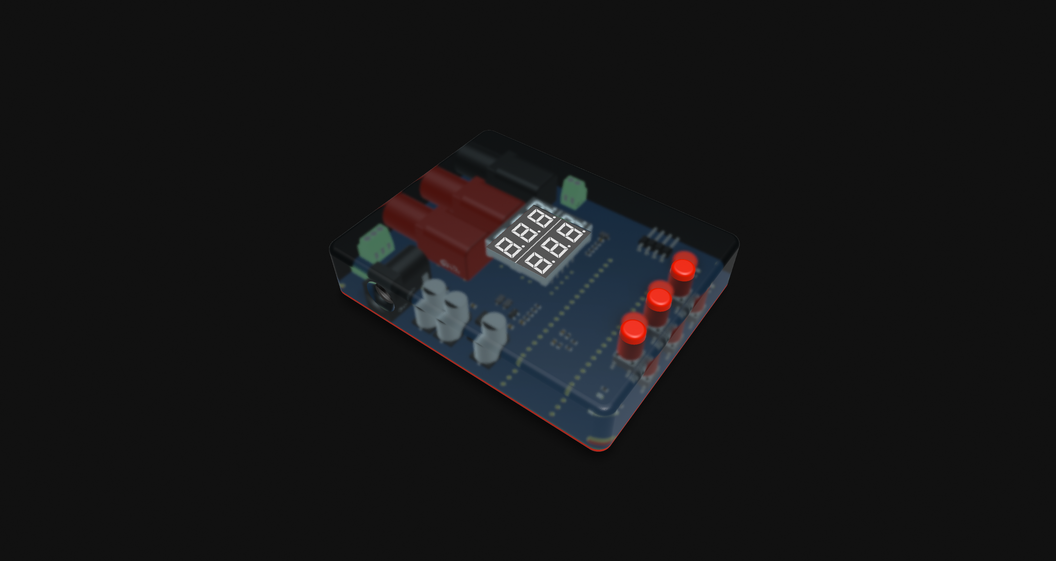
  Overall project display
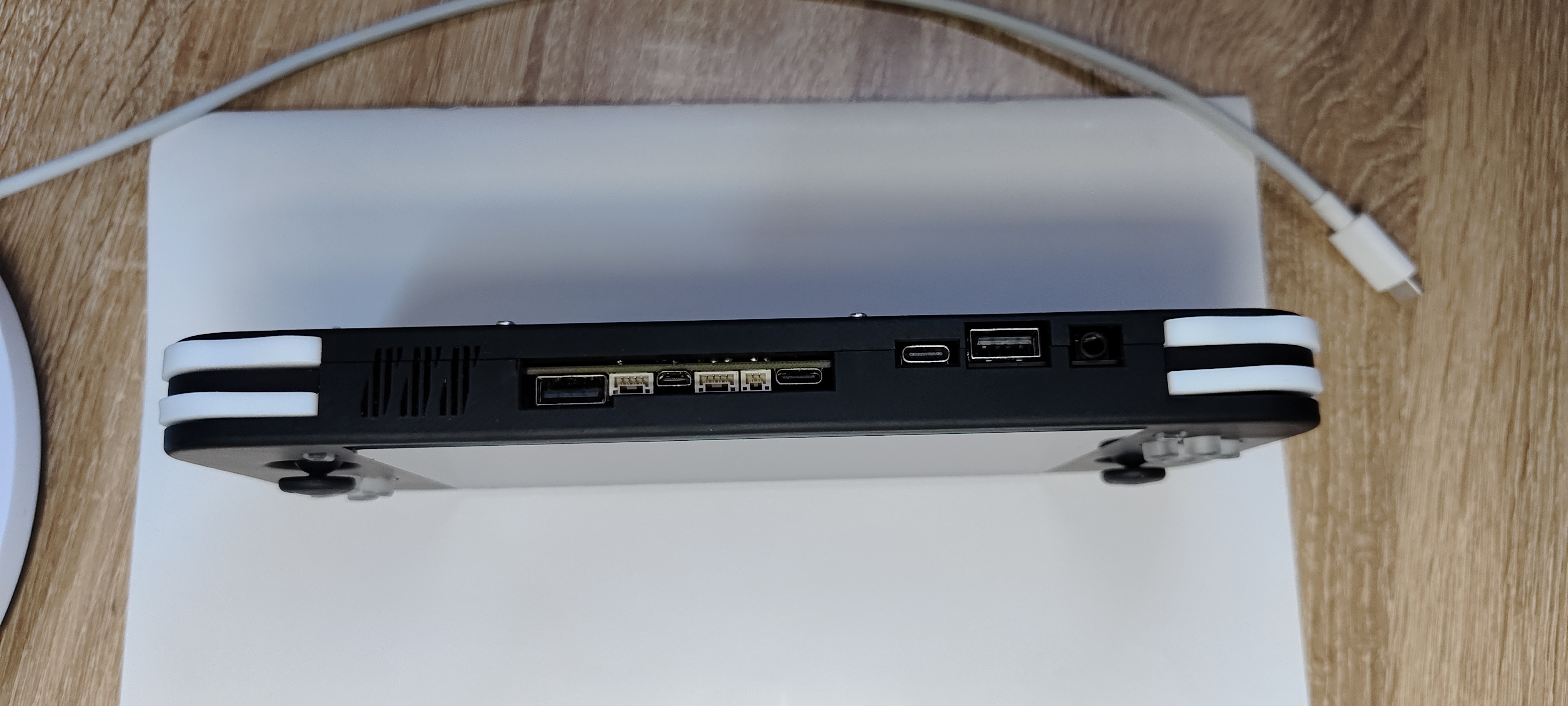
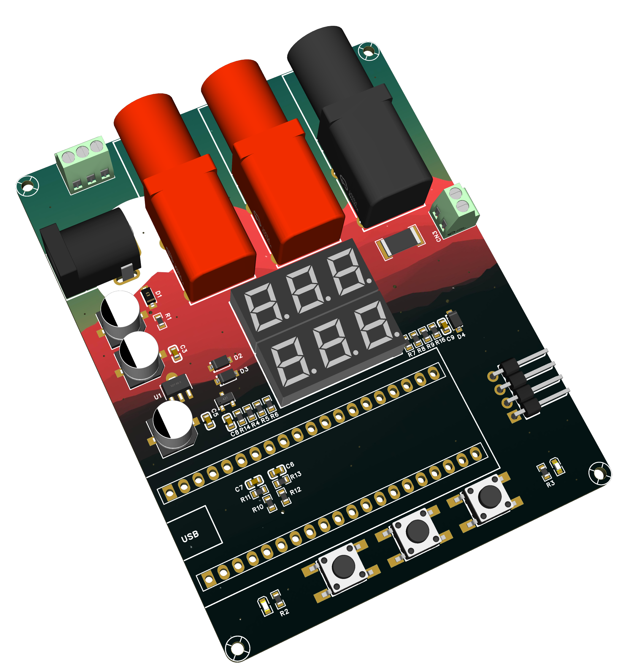
  Hardware Label
  Hardware Design Details


 ). Development stage:
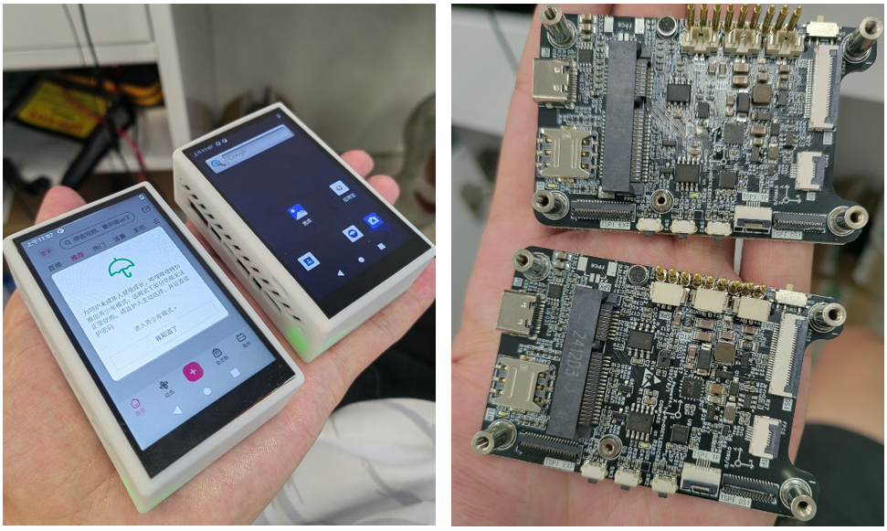


 京公网安备 11010802033920号

 RN55C9532DR36


