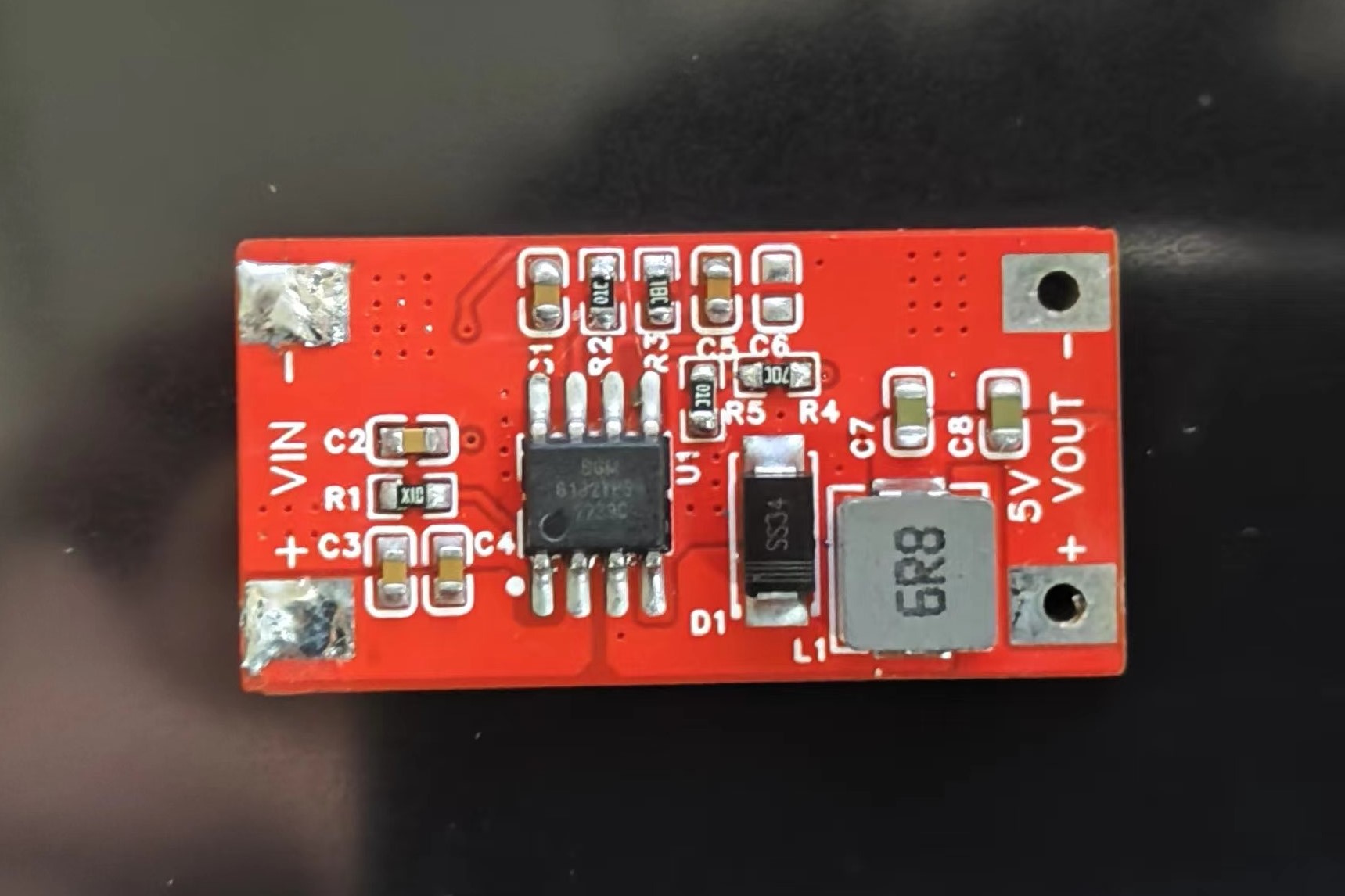
SGM6132 is a current-mode buck regulator with an internal power MOSFET. This device achieves 3A continuous output current over a wide input supply range of 4.5V to 28.5V, exhibiting good load and line regulation. The SGM6132's 1.4MHz switching frequency and current-mode operation provide fast transient response and mitigate loop stabilization. The SGM6132 is highly efficient, achieving a peak efficiency of 91% during operation. In shutdown mode, the regulator's supply current is less than 18μA. Protection features include cycle-by-cycle current limiting and thermal shutdown. The device also includes internal and external adjustable soft-start functions to limit inrush current and prevent output voltage overshoot.
, and DVD/PVR devices.
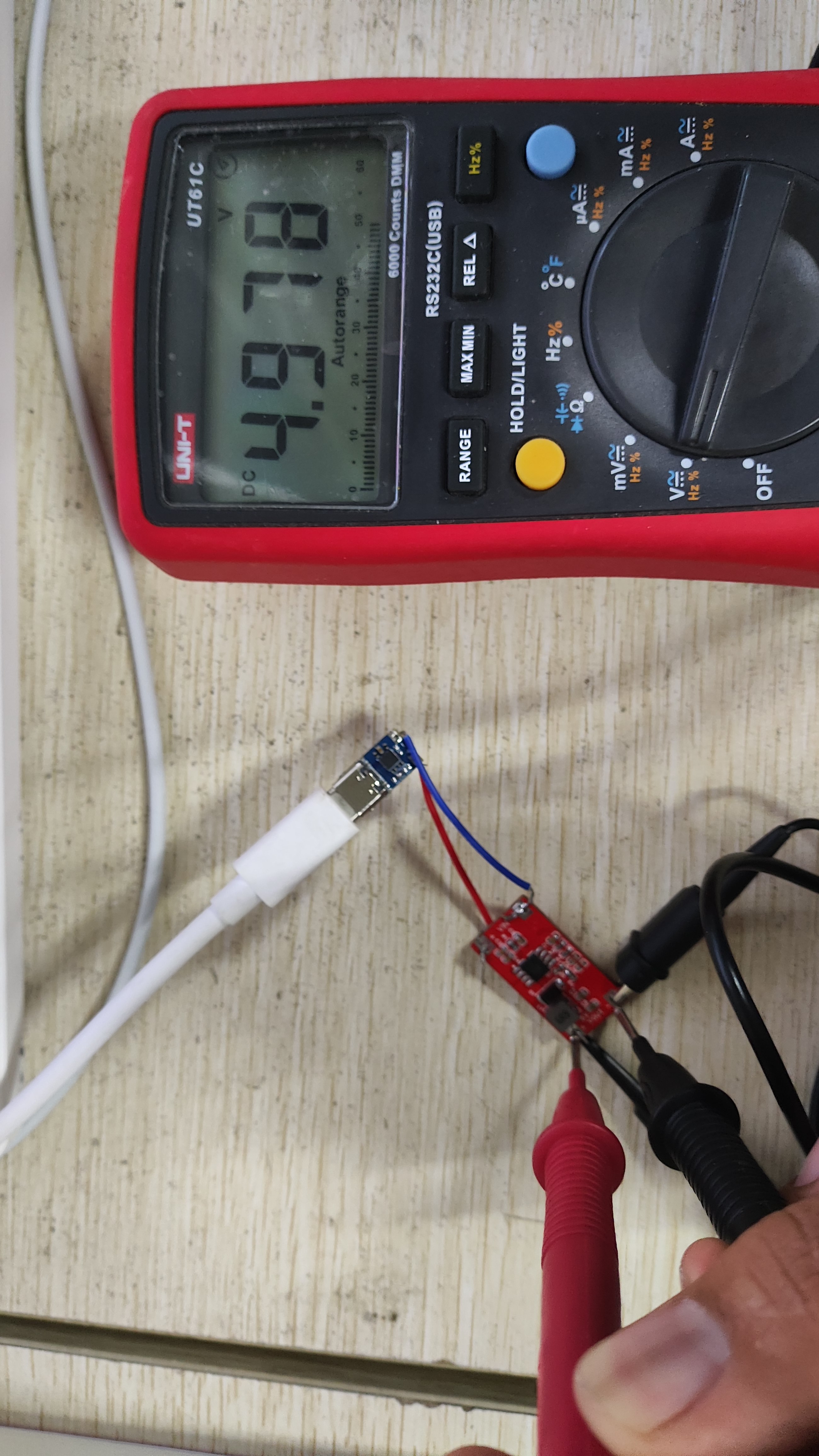
an input voltage of 11.93V and an output voltage of 4.978V, AC coupled. See the image below for details.
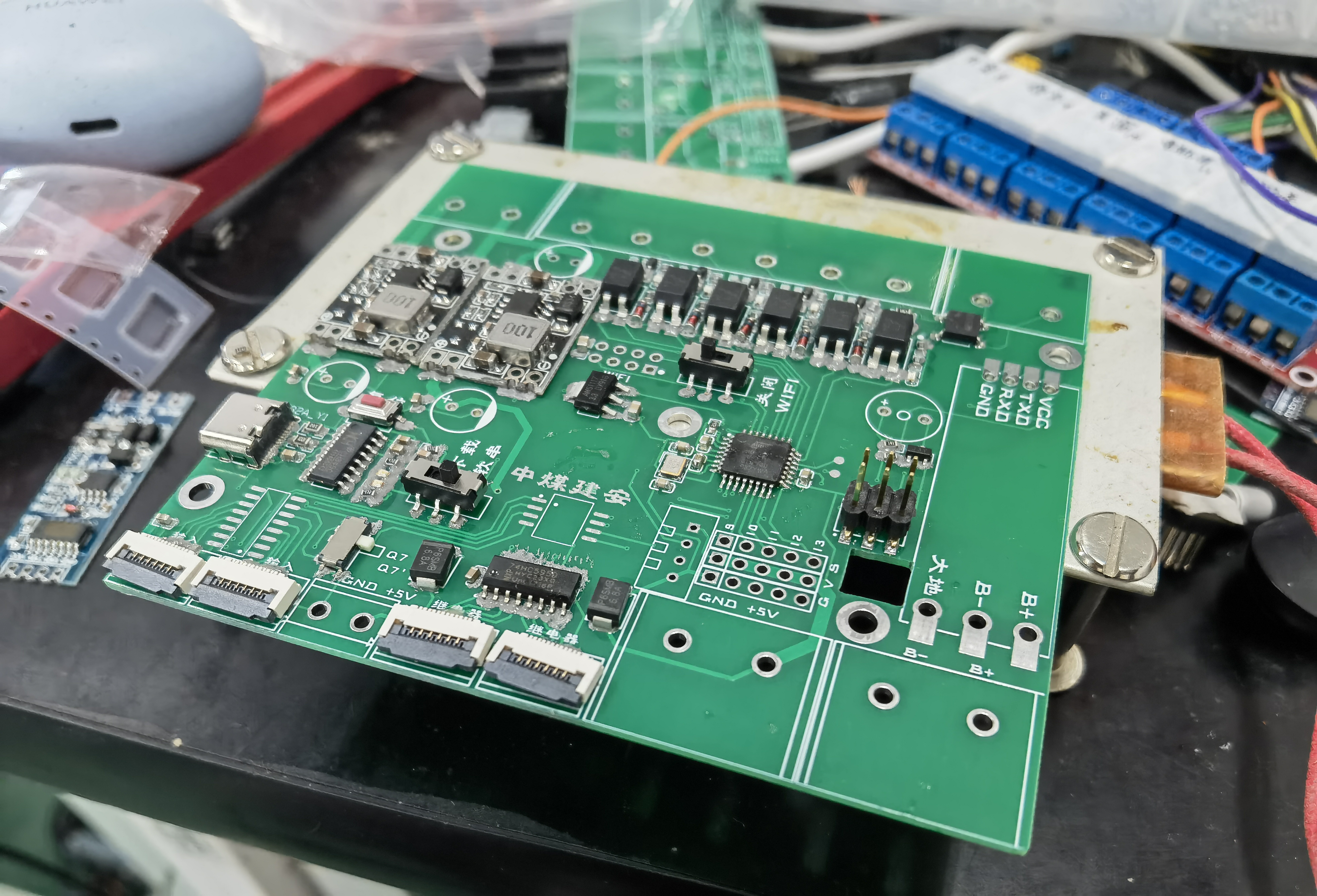
This is a cyberpunk cake, a birthday cake. It uses two layers of PCB stacked together. The top PCB is in the attachment. The code isn't very good, but you can modify it yourself.
This cake uses the Chinheng CH552 microcontroller, an enhanced E8051 core microcontroller compatible with the MCS51 instruction set. 79% of its instructions are single-byte, single-cycle instructions, with an average instruction speed 8-15 times faster than the standard MCS51.
Core: Enhanced E8051 core, compatible with the MCS51 instruction set, 79% of its instructions are single-byte, single-cycle instructions, with an average instruction speed 8-15 times faster than the standard MCS51, featuring XRAM fast data copy instructions and dual DPTR pointers.
ROM: 16KB of reprogrammable non-volatile ROM, which can be used entirely for program storage; or it can be divided into a 14KB program storage area and a 2KB bootloader/ISP program area.
DataFlash: 128 bytes of erasable non-volatile data memory, supporting byte-by-byte data rewriting.
RAM: 256 bytes of internal iRAM for fast data buffering and stack access; 1KB of on-chip xRAM for large-scale data buffering and DMA direct memory access.
USB: Embedded USB controller and USB transceiver, supporting USB-Device mode, USB Type-C master/slave detection, and USB 2.0 full-speed 12Mbps or low-speed 1.5Mbps. Supports a maximum data packet size of 64 bytes, built-in FIFO, and DMA support.
Timer: 3 timers, T0/T1/T2 are standard MCS51 timers.
Capture: Timer T2 is expanded to support 2-channel signal capture.
PWM: 2 PWM outputs, PWM1/PWM2 are 2-channel 8-bit PWM outputs.
UART: 2 asynchronous serial ports, both supporting higher communication baud rates; UART0 is a standard MCS51 serial port.
SPI: The SPI controller has a built-in FIFO, with a clock frequency up to half the system master frequency Fsys. It supports serial data input/output simplex multiplexing and Master/Slave modes
. ADC: A 4-channel 8-bit A/D converter supporting voltage comparison.
Touch-Key: 6-channel capacitance detection, supporting up to 15 touch buttons and independent timer interrupts.
GPIO: Supports up to 17 GPIO pins (including XI/XO, RST, and USB signal pins).
Interrupt: Supports 14 interrupt signal sources, including 6 interrupts compatible with the standard MCS51 (INT0, T0, INT1, T1,
UART0, T2), and an additional 8 interrupts (SPI0, TKEY, USB, ADC, UART1, PWMX, GPIO, WDOG), where GPIO interrupts can be selected from 7 pins.
Watch-Dog: An 8-bit presettable watchdog timer WDOG supports timer interrupts.
Reset: Supports 4 reset signal sources, built-in power-on reset, supports software reset and watchdog overflow reset, and optional external input reset pin.
Clock: Built-in 24MHz clock source, supports external crystal via multiplexed GPIO pins.
Power: Built-in 5V to 3.3V low-dropout voltage regulator, supports 5V, 3.3V, or even 2.8V power supply voltage. Supports low-power sleep mode, and external wake-up via USB, UART0, UART1, SPI0, and some GPIO pins.
The chip has a unique built-in ID number.
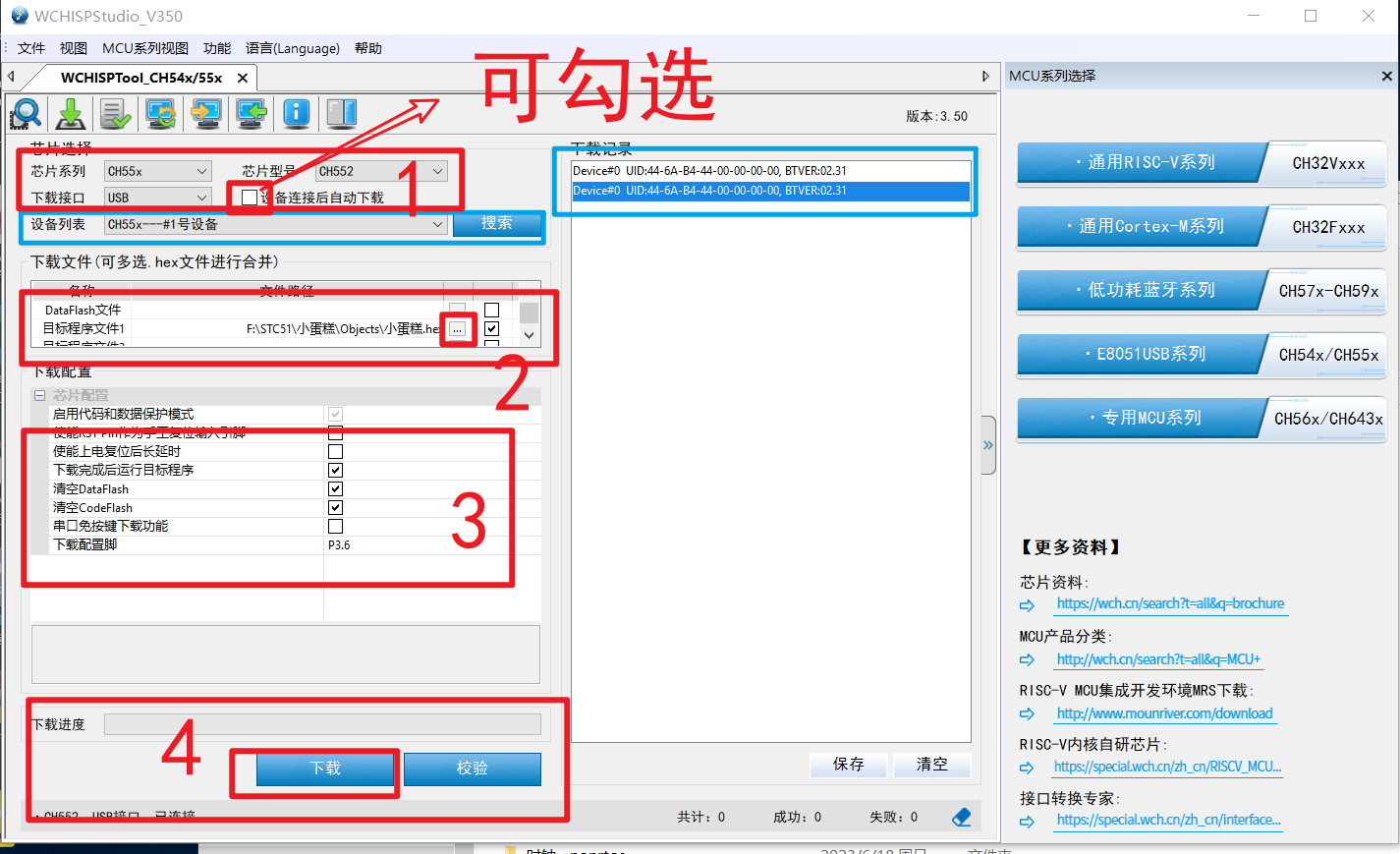
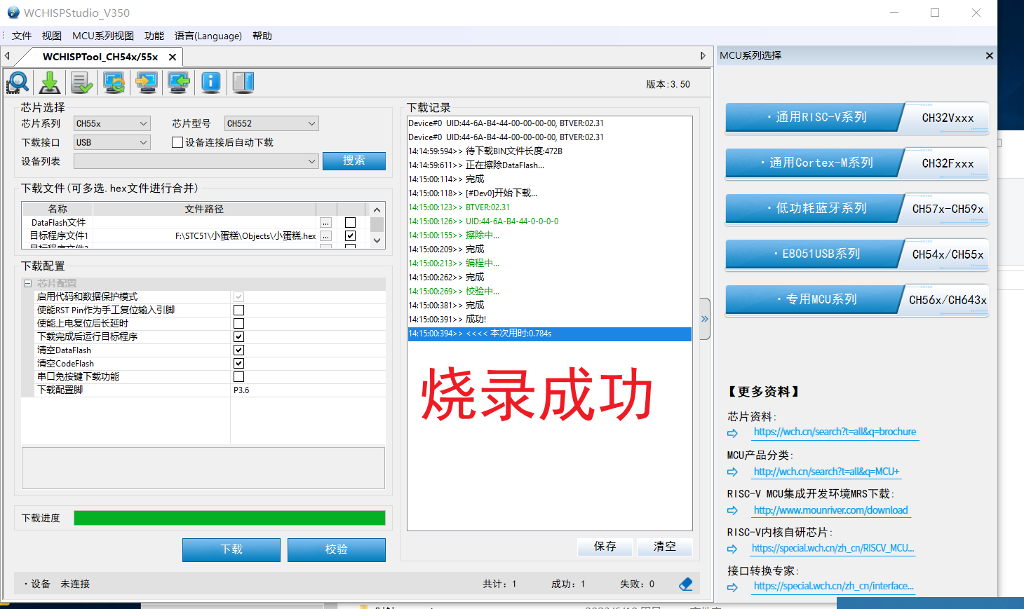
Programming method: Press and hold load1, then plug in the USB to connect to the host computer for programming
(WCHISPTool_Setup.exe).

ProProject_Mini Cake Top Layer_2023-10-28.epro
Small cake.7z
WCHISPTool_Setup.exe
VID_20231028_140415.mp4
PDF_CyberCake.zip
Altium_Cybercake.zip
PADS_CyberCake.zip
BOM_CyberCake.xlsx
97292
Call for Designs | Smart Community Control System
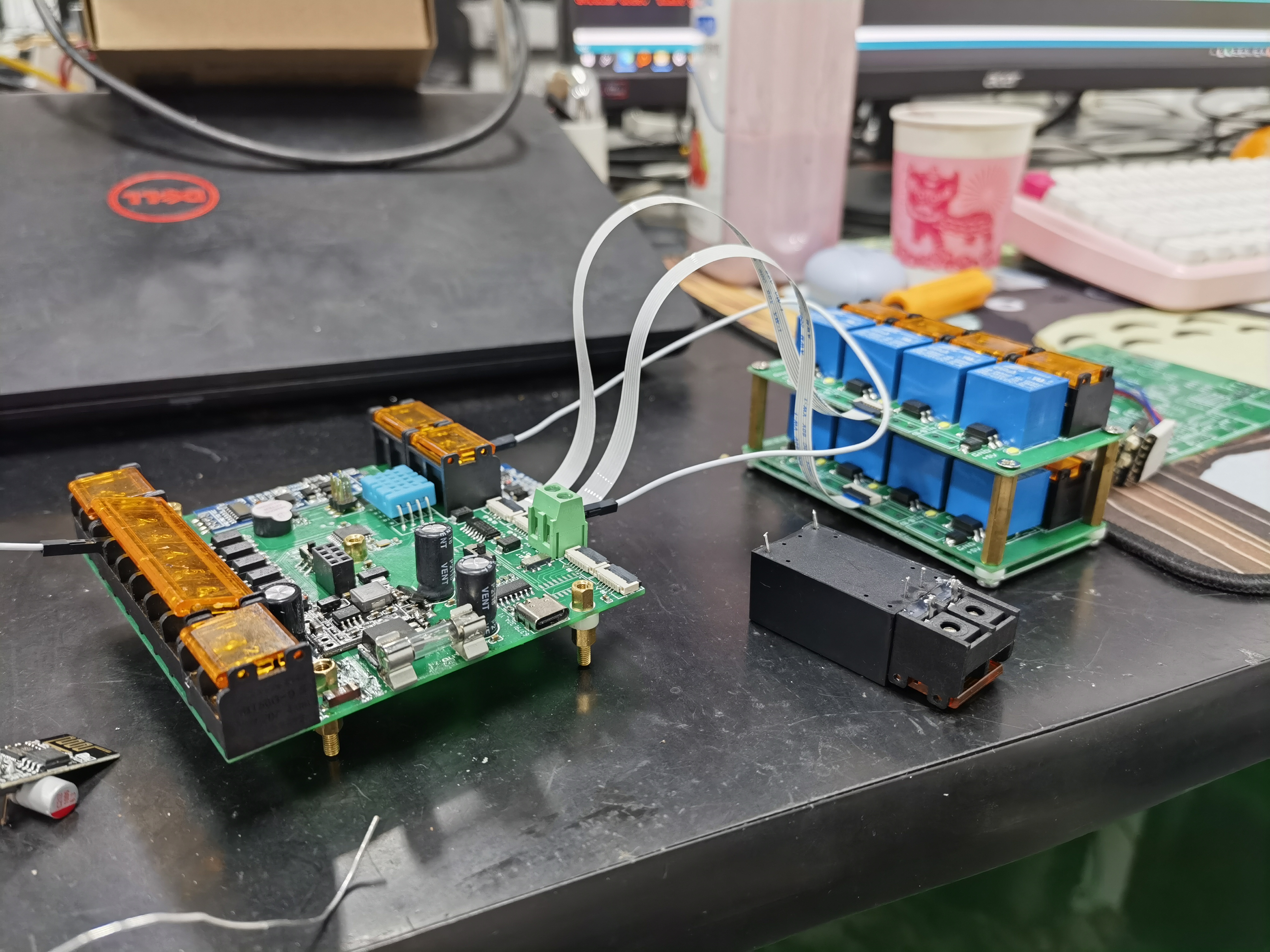
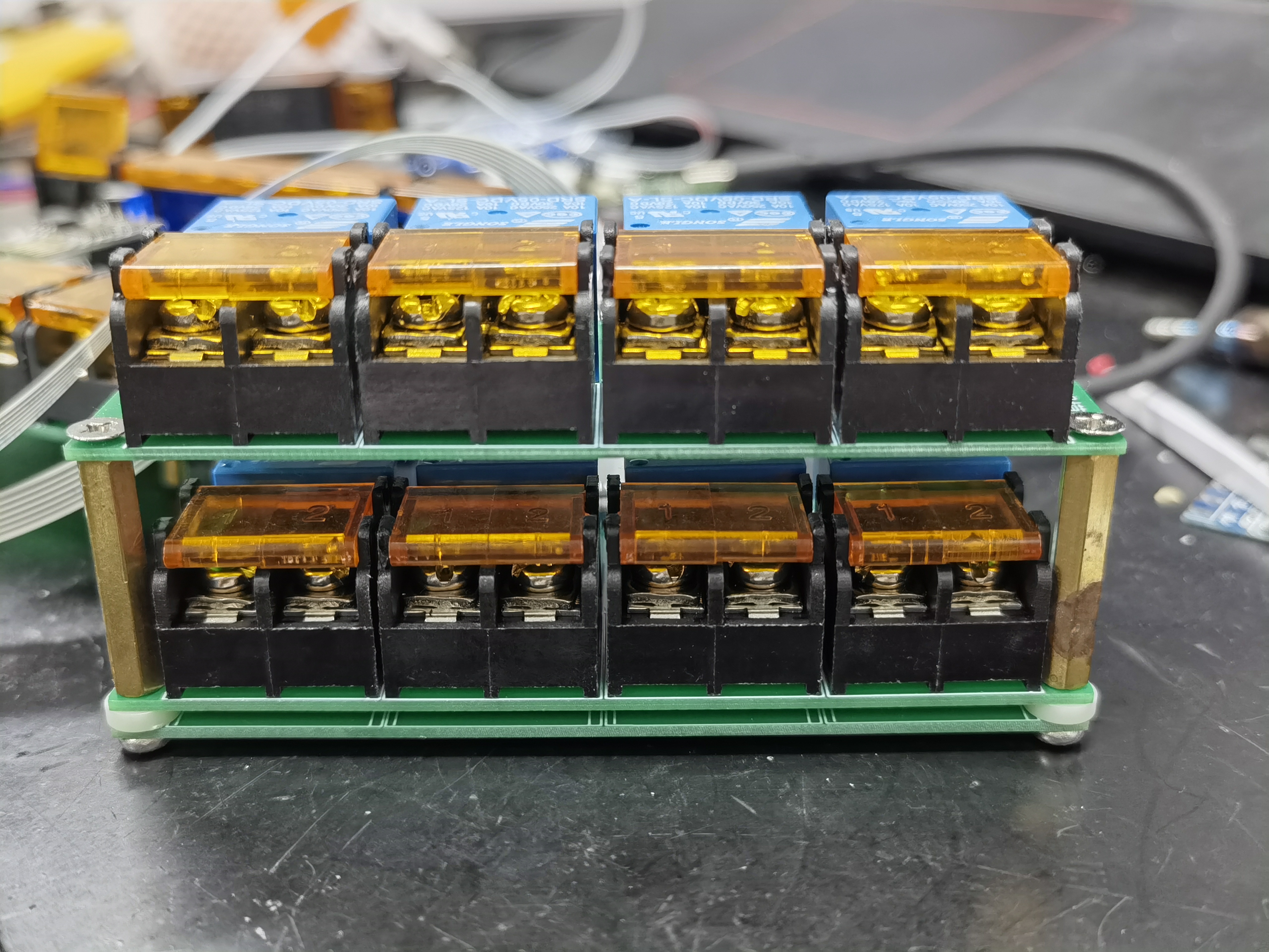
An IoT controller that remotely controls 8 relays via the Alibaba Cloud platform to achieve relevant functions.
Introduction:
This is an IoT control system based on the Alibaba Cloud IoT platform. Through this system, users can remotely control the switching of various electrical devices, achieving intelligent control.
The system utilizes the powerful functions of the Alibaba Cloud platform to acquire real-time status information of electrical equipment and feed it back to the cloud, allowing users to monitor and manage equipment anytime, anywhere.
One of the key technological innovations is the use of circuit boards designed by LCSC EDA and prototyped from JLCSC, providing efficient and reliable hardware support for the system.
Soldering Process:
First, a separate design for surface-mount components is used for soldering on an iron plate
, ensuring easy disassembly and replacement of components, while each relay has protection. An ESP8266 is used to receive cloud information, and ADRUINO is used to process information and control device
signal input detection. Remember not to add Zener diodes, otherwise problems will occur
. Also, don't add unnecessary switches; after a while, you'll forget what each switch does!
Cloud Control Interface Tutorial:
Based on Alibaba Cloud IoT Smart Home Tutorial Explanation and Debugging Webpage Domain_Bilibili_bilibili
Program Description:
Due to the internal circulation nature of the program, the attached file is the ATMEGA2560 program, which can connect to the Alibaba Cloud IoT control pin output signal!
The part that needs to be modified is the triplet information!!
/* WiFi name and password (This needs to be modified) */ String wifi_name = "WLAN"; String wifi_pwd = "fuqiangminzhu"; /* Alibaba Cloud Smart Classroom triplet (This needs to be modified) *///{"PRODUCT_KEY" : "a18nN6sBQO", "DEVICE_NAME" : "A_101_R", "DEVICE_SECRET" : "1ccb3db8dd115be7c1d01ef9f191f60"}String PRODUCT_KEY1 = "a1HQkQx7dL";String DEVICE_NAME1 = "A_commuity";String DEVICE_SECRET1 = "563ecbc0e7647834742805fc6ef27d1";
The rest are simple program concatenations.
Smart Community.txt
PDF_Call for Design_Smart Community Control System.zip
Altium_Call for Projects_Smart Community Control System.zip
PADS_Call for Design_Smart Community Control System.zip
BOM (Bill of Materials) - Solicitation Notice - Smart Community Control System.xlsx
97293
STM32-based desktop clock/weather display/desktop pet
STM32-based desktop clock/weather display/desktop pet project
Project Description:
This project uses the CC-BY-NC-SA 3.0 license. No one may use this project for commercial purposes. Any modifications must be open-sourced and the original project source must be acknowledged!
This project uses the CC-BY-NC-SA 3.0 license. No one may use this project for commercial purposes. Any modifications must be open-sourced and the original project source must be acknowledged!
This project uses the CC-BY-NC-SA 3.0 license. No one may use this project for commercial purposes. Any modifications must be open-sourced and the original project source must be acknowledged!
This is the author's technical verification project. All optimization methods and module drivers were written by the author alone. Since this is the first time designing such a large project, practicality and cost were not given much consideration; it's simply following in the footsteps of experts to DIY a small TV. Replicating carries risks; please consider carefully. The project code, drawings, and models will all be open-sourced. If any experts have suggestions for modification or optimization, please point them out. The author will select the best suggestions and make modifications accordingly.
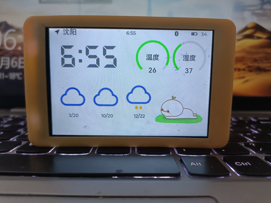
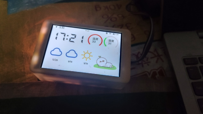
This project is a small TV desktop clock/weather display/desktop pet project based on the STM32F412 chip and multiple peripheral modules.
The mini TV automatically connects to the internet to update the date, time, and weather information, which is then displayed on the screen.
It is powered on/off and allows left/right page turning via three touch buttons on the top. Wirelessly, it supports a dedicated app for Bluetooth pairing and setting up memos (the app and corresponding firmware are currently under development). Pressing the middle button automatically enters low-power mode, and pressing it again wakes it up. In low-power mode, the entire board's 3.3V power supply is turned off; only the STM32 and touch chip remain powered (the STM32 is in low-power mode). It automatically wakes up at midnight every day, connects to the internet to retrieve the time and weather information, saves it, and then automatically

goes into sleep mode. The entire development cycle of the mini TV was nearly a year and a half, filled with complex expectations/compromises and functional implementation issues. The hardware and software design ideas and architecture are introduced below, but the purely technical details are a bit dry. I'll create a post later to discuss the development process from a personal perspective; those interested can treat it as a story.
Mini TV Desktop Clock - Hardware Design Ideas and Introduction - JLCPCB EDA Open Source Hardware Platform (oshwhub.com)
Mini TV Desktop Clock - Software Design Architecture - JLCPCB EDA Open Source Hardware Platform (oshwhub.com)
Currently, the Mini TV uses an STM32 microcontroller paired with two wireless modules. The estimated cost per unit is over 200 RMB, and the final functionality is not powerful. It is not recommended for players seeking low-cost solutions to replicate this design.
Item
Costs (Unit Price Excluding Shipping)
Purchase Location
Screen
37
3.5-inch LCD Screen Display IPS Screen SPI Serial Port ILI9488 Capacitive Touch Screen Brand New Color Screen ST7796 - Taobao (taobao.com)
STM32F412VGT6
15
Second-hand
Shell on Xianyu (9000R Resin Material) (Recommended, but will yellow)
35
LCSC 3D Monkey
Shell (ASA) (Choose one from resin material)
86.09
LCSC 3D Monkey
PCB
20 (Possible to get it for free)
LCSC
AI-WB2 WIFI/Bluetooth Module
6
Anxinke's Main WiFi and Bluetooth Combination Module Ai-WB2-12F Package Compatible with ESP12F Serial Port Transparent Transmission - Taobao (taobao.com)
EC-01G NB-IOT/Positioning Module
37.9
Anxinke NB-IoT+GPS/BDS Positioning Module/EC-01G Wireless Serial Communication Module/Data Transparent Transmission - Taobao (taobao.com)
NB-IOT Antenna
2
Full-Band LTE 4G 5G NB-IoT 8DB Built-in 900m915 3G GSM PCB FPC Patch Antenna - Taobao (taobao.com)
GPS Antenna (Optional)
7
Active GPS Beidou Dual-Mode Built-in Antenna High Gain Navigation and Positioning BD Ceramic Amplification Dual-Frequency Antenna - Taobao (taobao.com)
Battery (7000mAh)
61.5
Zhongshunxin 7000mAh Mobile Outdoor Backup Power Bank Polymer Lithium Battery 3.7V 105080 - Taobao (taobao.com)
IoT Card
15
NB SIM Card Industrial NB-IoT Card Patch Card Plug-in Card NB-IoT, Mobile NB NB Module - Taobao (taobao.com)
Other Miscellaneous Items (Components, etc.)
Approximately 20
Most of the LCSC
projects have been open source since the fourth (actually the Nth) version, and in the future (may) be updated to a low-cost version using ESP32 and a high-performance touchscreen version using ARM-Linux.
Replica Tutorial:
1. All files in this project were drawn using Alitium Designer. Free JLC prototyping may not be available; importing the professional version is only for easy viewing.
2. Prototype the PCB and casing. The PCB thickness is 1.2mm. Purchase original components. The W25Q128 must have an FV suffix, and the battery must have a protection board.
3. Register a Xinzhi Weather account and save your KEY.
4. Solder all components. Since FPC connectors are very difficult to solder, it is recommended to solder them first to avoid damaging the entire board. Soldering is recommended using solder paste and a heating table/hot air gun. Some areas may require reshaping with a soldering iron. Components with plastic parts, such as the SIM card slot, Type-C interface, and RTC battery holder, are recommended to be soldered later. There is some conflict between the SIM card slot and the 3.3V step-up/step-down inductor and the 32.768K crystal oscillator; replicators should decide on their soldering method based on their skill level. SD card related circuitry is not currently used due to firmware limitations and can be left unsoldered for now.
5. Apply three pieces of copper foil tape to the top of the casing. Solder the leads to the three test points on the back of the PCB battery holder. The middle lead passes through the screen support frame on the back casing and is soldered to the leftmost point. The remaining two points are in the same position as the buttons. It is recommended to keep the leads as short as possible to avoid interference from inter-line capacitance to the touch screen. The battery interface is positive on the left and negative on the right. The middle point is the soldering point for the NTC detection line. If using the NTC function, R24 needs to be left unsoldered.
6. Compile the download algorithm: Open the .uvprojx file in the download algorithm. If your Keil is installed in the default directory, you can compile directly. If it is not in the default directory, it is recommended to first uncheck the box before "user commands" in target->user, and then manually copy the download algorithm file to the corresponding directory of Keil after compilation. For convenience, you can also directly copy the existing F412V4_Dflash.FLM file in the project root directory to the corresponding download algorithm storage directory on your computer.
7. Open the main project program, open USER/APP.c in the project pane, and replace the value of the macro definition USER_KEY with your previously saved key.
8. After compiling the main project, use a downloader to connect to the small TV download interface to download directly. The screen backlight should be on during the download process, which is normal. If an error message appears indicating that the download algorithm for the corresponding region was not found, it is recommended to go back and check if the copied path of the download algorithm is correct and if it matches the location where Keil automatically retrieves the download algorithm.
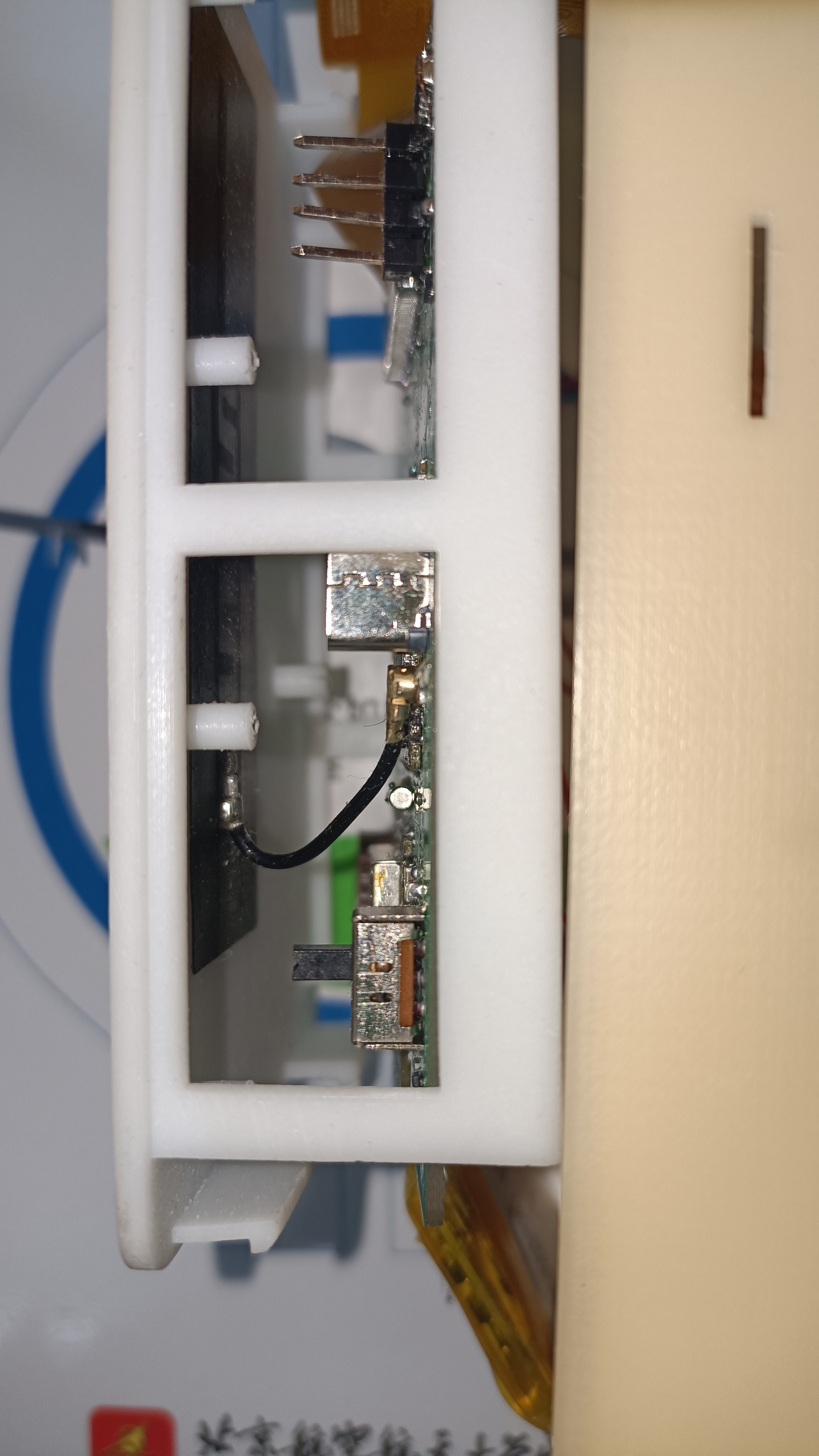
9. Attach the purchased NB-IoT antenna to the back cover, ensuring the antenna connector reaches the socket. (If you wish to try developing GPS functionality, you can install a GPS antenna and attach it to the GPS area of the PCB; however, if you've already reached this step, you probably don't need this replication tutorial.)
10. After plugging in the screen, use M1 self-tapping screws to screw the PCB onto the back cover, ensuring the connector and switch positions are correctly aligned.
11. Fold the screen over and place it on the screen support bracket on the back cover. Be careful not to break the flywire of the touch buttons. Also, the center of the screen's appearance should not be centered on the front cover of the small TV (to ensure the screen display area aligns with the opening in the cover). After inserting the screen into the slot, close the back cover.
Project Defects (Known Bugs):
1. The EC-01G module has GPS positioning capability, but (possibly) it cannot be used quickly due to signal issues.
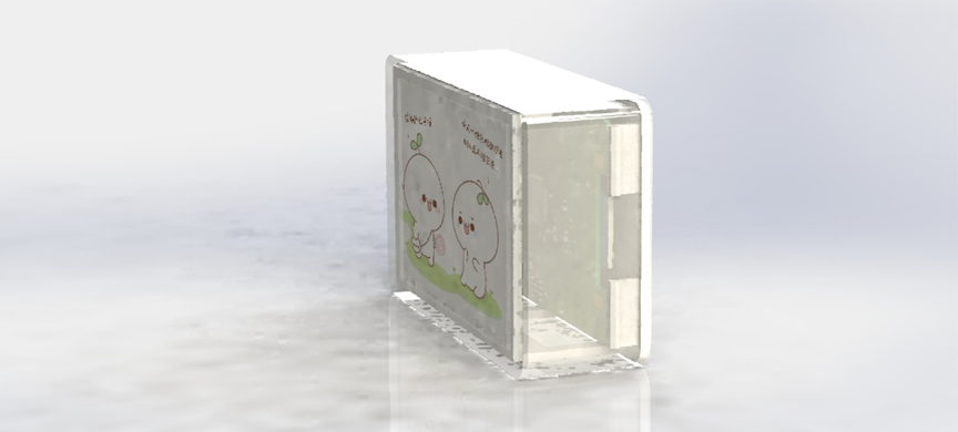
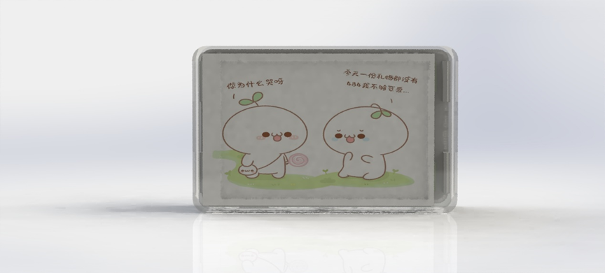
2. The shell structure has average strength and tends to yellow after prolonged use. A white, semi-transparent 3D printing material with good weather resistance needs to be found.
3. After waking up, the system determines whether it is an automatic wake-up at midnight by comparing the alarm clock setting and the RTC time. If the button switch time happens to coincide with the alarm wake-up time, the program will malfunction.
4. The time obtained from network synchronization includes network latency, causing a difference of a few seconds between the internal time of the small TV and the actual time.
5. The desktop pet lacks continuity between different animations and has no interactive capabilities.
6. The drivers for the WIFI/Bluetooth and NB-IoT modules are still significantly incomplete and do not yet support true multi-threaded operation.
7. The program architecture does not allow automatic re-acquisition of information after a Wi-Fi disconnection and reconnection.
8. … (There are still some issues)
The main project code is being organized, and
attached images will be uploaded within a few days:
1. Disassembly diagram
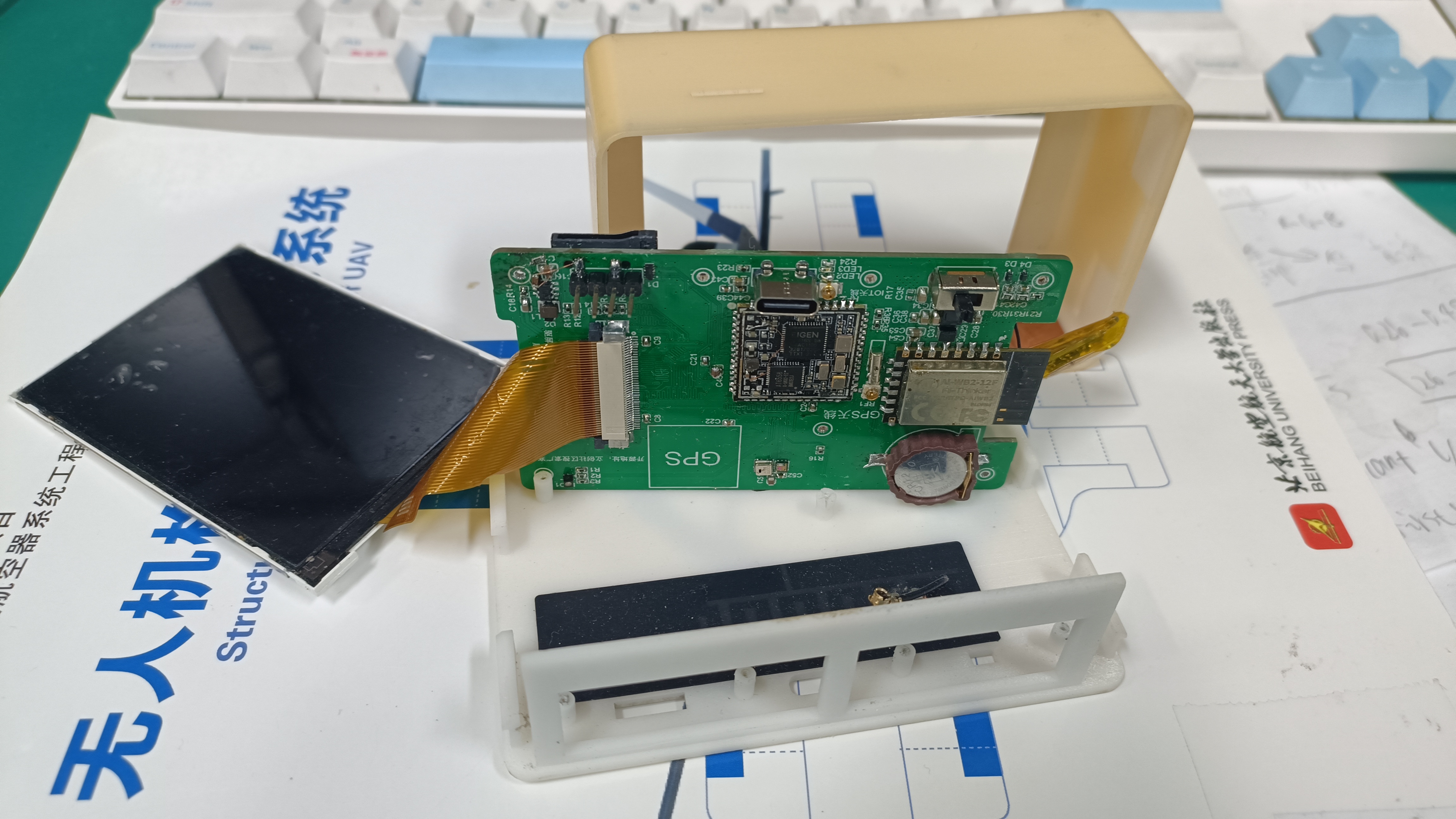
2. Copper foil tape and soldered traces for the touchscreen (ignore the adjacent flying wire chip; this is an older version of the PCB and does not yet integrate the AT24C08)
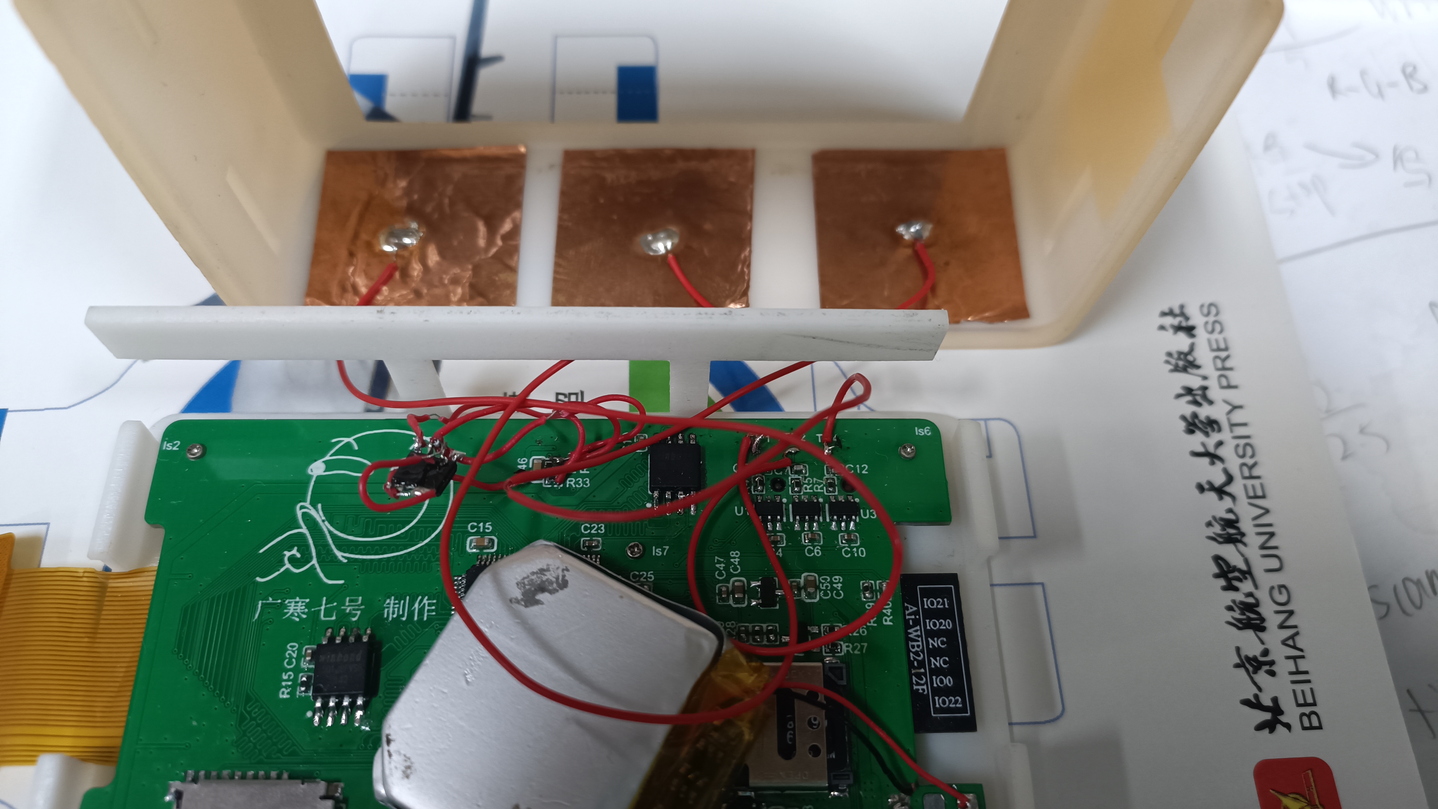
3. Back of the motherboard and the attached antenna
4. Antenna connection method; when attaching the antenna, ensure the connector is aligned correctly.
Other images include overall appearance and renderings.


PCB.zip
Download Algorithm.zip
Shell.zip
Main project code (incomplete, contains major bugs, but usable). 7z
PDF_STM32-based Mini TV Desktop Clock - Weather Display - Desktop Pet.zip
Altium-based STM32 mini desktop clock with weather display and desktop pet. zip
PADS_STM32-based Mini TV Desktop Clock_Weather Display_Desktop Pet.zip
BOM_STM32-based Mini TV Desktop Clock_Weather Display_Desktop Pet.xlsx
97294
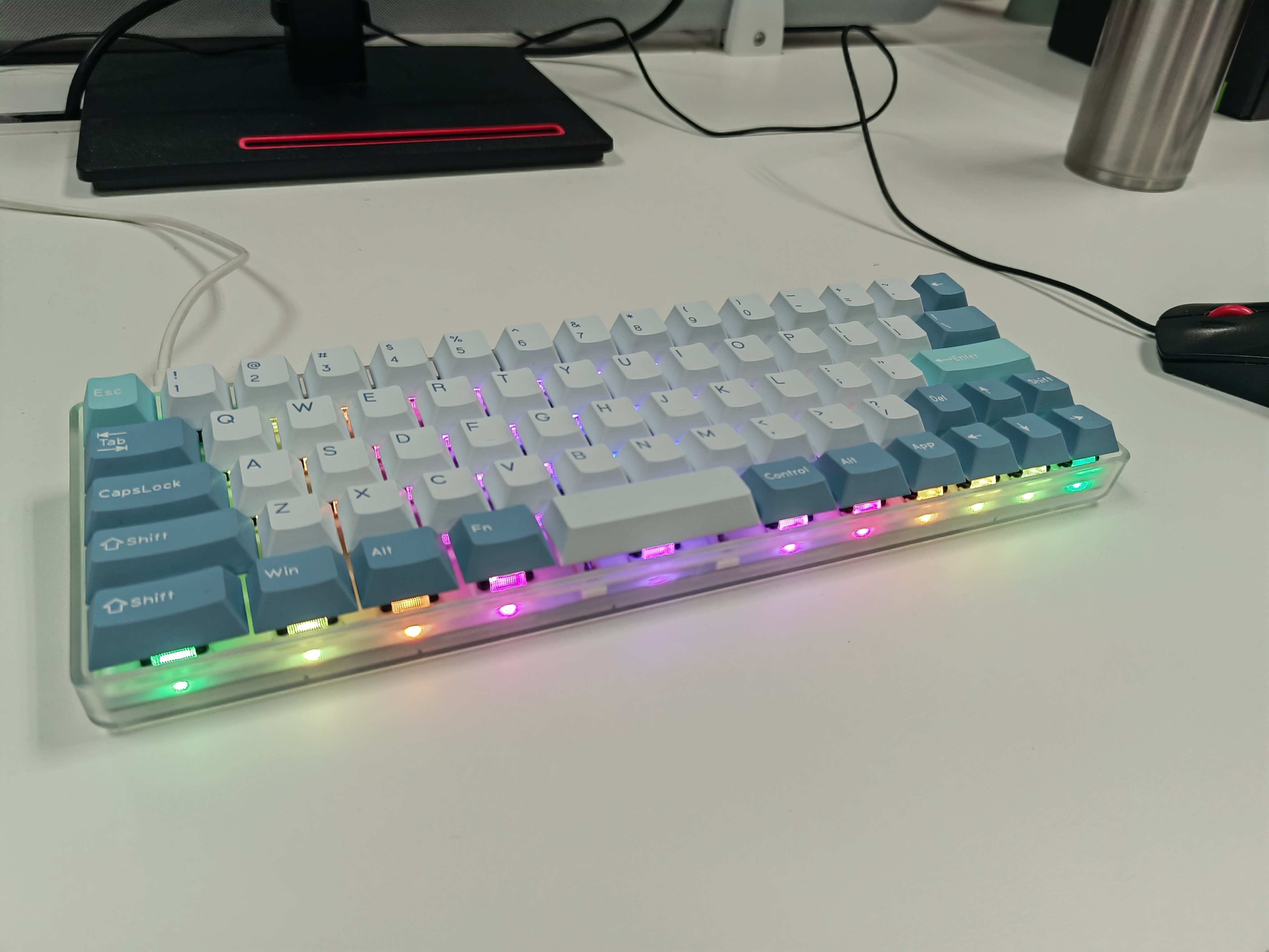
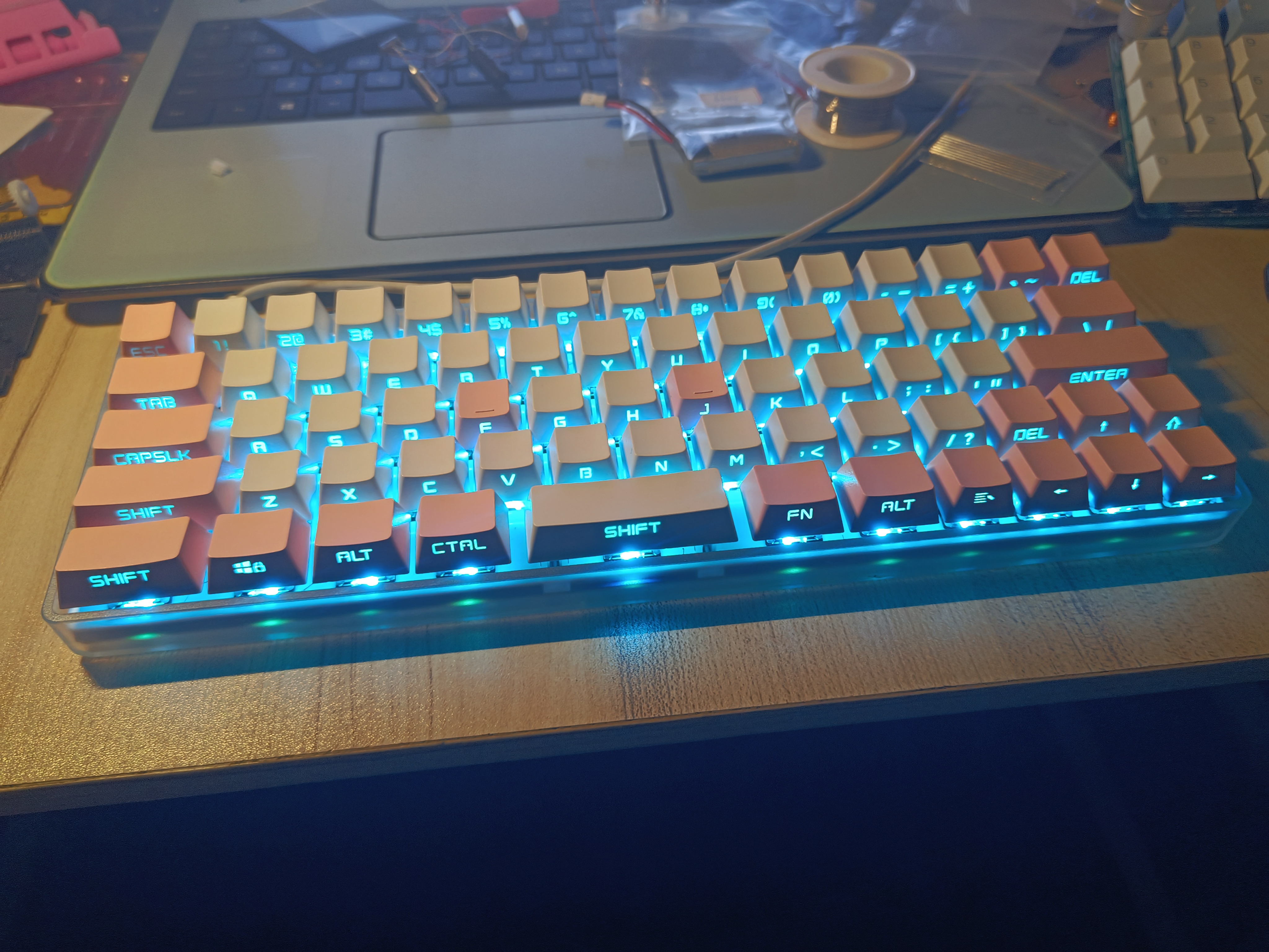
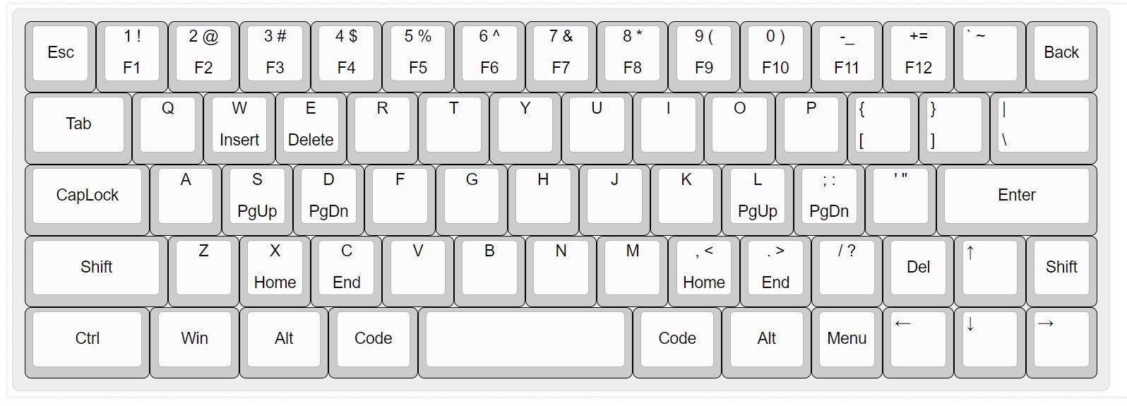
[Verified] Minila Keyboard - Starlight 67
A 60% layout wired single-mode programmable keyboard suitable for programmers, based on the STM32F103RBT6, using vial firmware based on qmk.
This document introduces
a wired single-mode keyboard based on the STM32F103RBT6, with 60% layout and lower LED positions, using the Vial firmware based on QMK.
For details, please see the Bilibili video: https://www.bilibili.com/video/BV1XH4y1d7i2/
Verification:
The keyboard has been tested and soldered, and has been used for over a month.
Firmware Description :
Bootloader
is attached (generic_boot20_pc13.bin
, downloaded from https://github.com/rogerclarkmelbourne/STM32duino-bootloader ) . Vial configuration
is attached (starlight_rev1_vial.bin)
. Basic Usage: The left and right sides of the large spacebar are layer toggles. After configuring the TAP_DANCE function, clicking triggers the spacebar, long-pressing switches to a layer, double-clicking switches to layer 2, and pressing simultaneously switches to layer 3. Layer 1 is the key combination and FN layer. The arrow keys control the mouse cursor; the left arrow key (Del) triggers a left mouse click, and the right arrow key (Shift) triggers a right mouse click. Layer 2 is the lighting control layer. Layer 3 is a custom macro layer. The buttons in the lower right and upper right corners are VIAL unlock buttons. Note that layer 0 is the default input layer, and the "|" key in layer 1 is the light switch; the light is off by default. The two spaces that appear after programming do not have key codes by default; it is recommended to configure TAP_DANCE or a simple layer switching function. The PCB is compatible with common plastic housings on the market, but due to interference from the bottom light position, part of the bottom support needs to be cut off with tools.
generic_boot20_pc13.bin
starlight_rev1_vial.bin
starlight_vial_rev1.vil
PDF_【Verified】minila layout keyboard - Starburst 67.zip
Altium_【Verified】minila layout keyboard - Starburst 67.zip
PADS - [Verified] Minila Keyboard Layout - Starlight 67.zip
BOM_【Verified】minila layout keyboard - Starburst 67.xlsx
97295
Traffic light system based on 51 microcontroller
The first practice project
I. Project Overview: This project
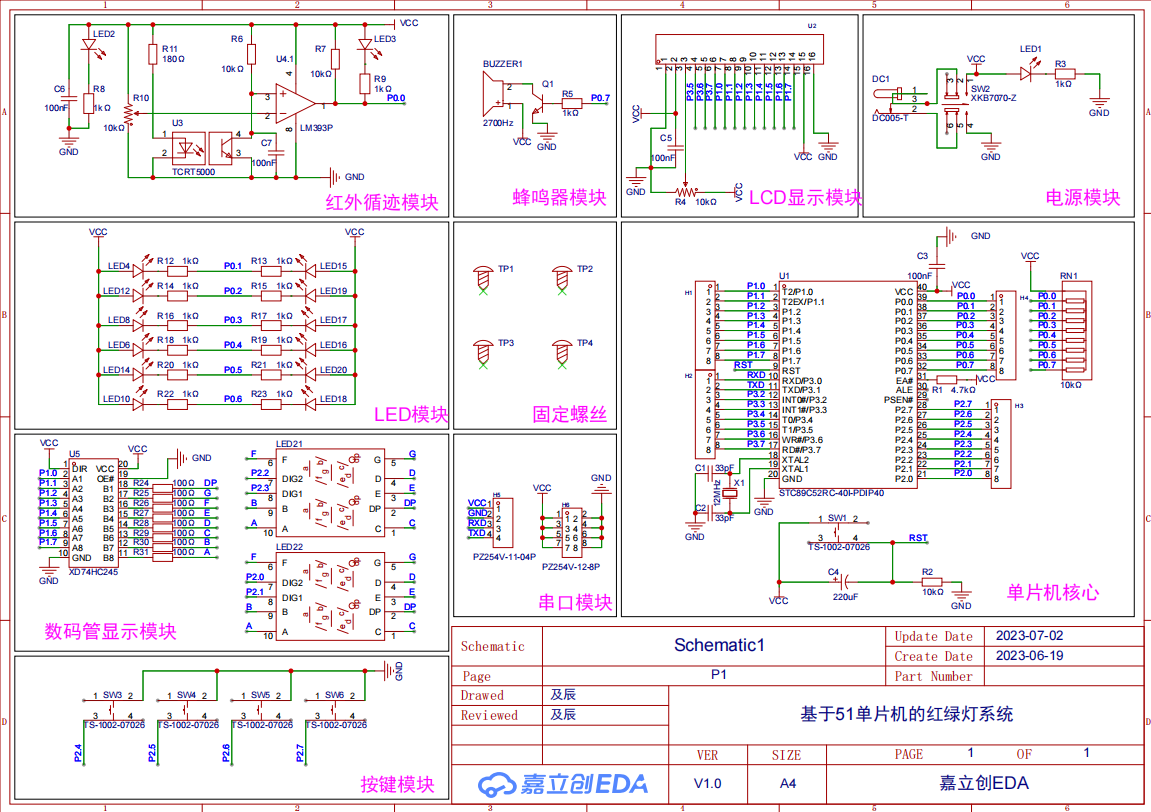
designs a traffic light system based on the 51 microcontroller. It uses two 0.56-inch common cathode LED displays to show the remaining seconds of red (green) lights in different directions. An infrared tracking module is used to detect pedestrians crossing the red light. Four sets of red, yellow, and blue LEDs simulate the traffic light status. An LCD1602 displays other information. A button module is used for information interaction (setting red light duration, whether to perform pedestrian crossing detection, etc.). The reset button, serial port circuit, all pins, VCC, and GND are all brought out for easy secondary development and the addition of peripherals.
II. Onboard Resources
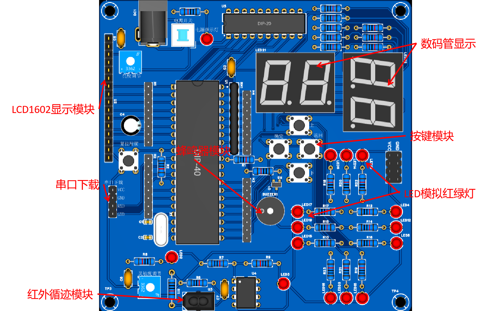
1. Main Control Chip: STC89C52RC; 2. Power Interface: DC, 2-pin connector; 3. LEDs: One power indicator, one infrared module status indicator, four sets of red, yellow, and green LEDs;
4. Buttons: One reset button, four function buttons; 5.
Debugging Interface: Serial port download and debugging interface, using a 2.54mm header connector;
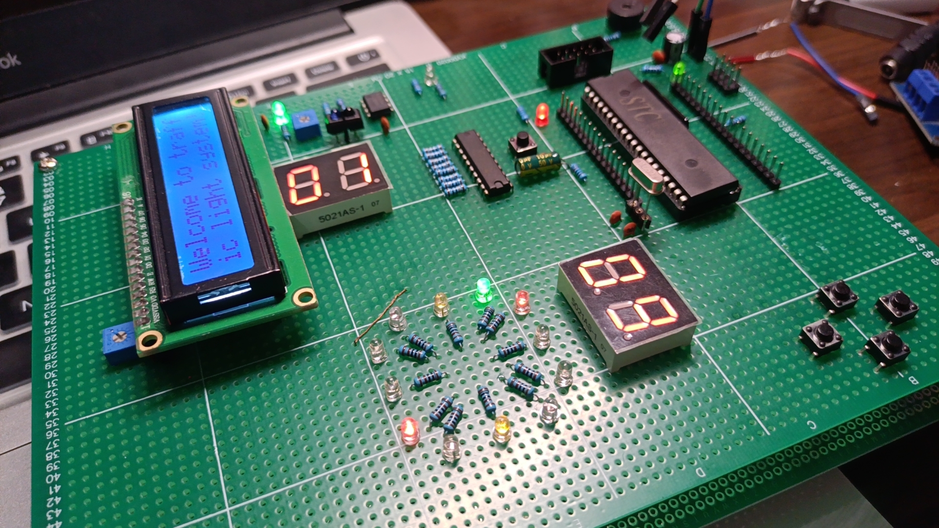
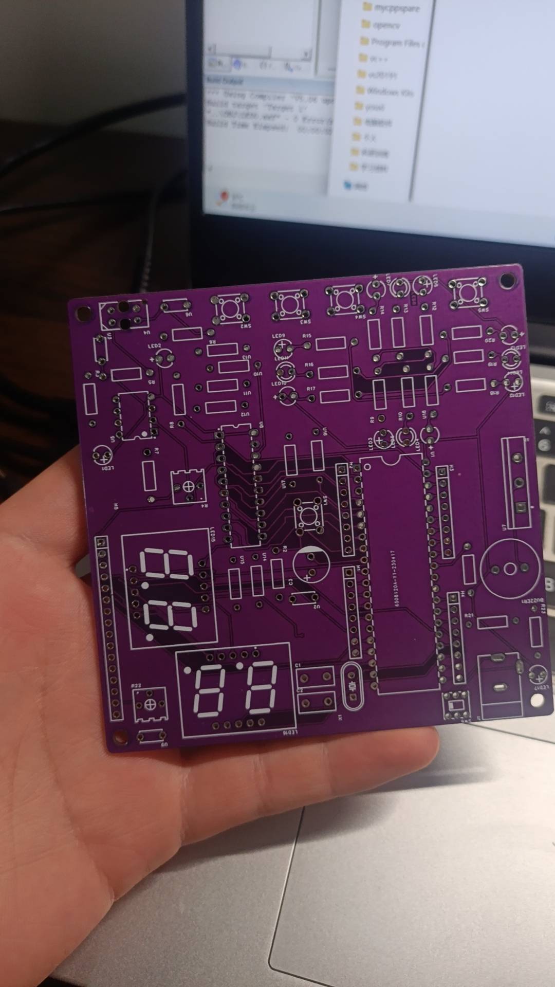
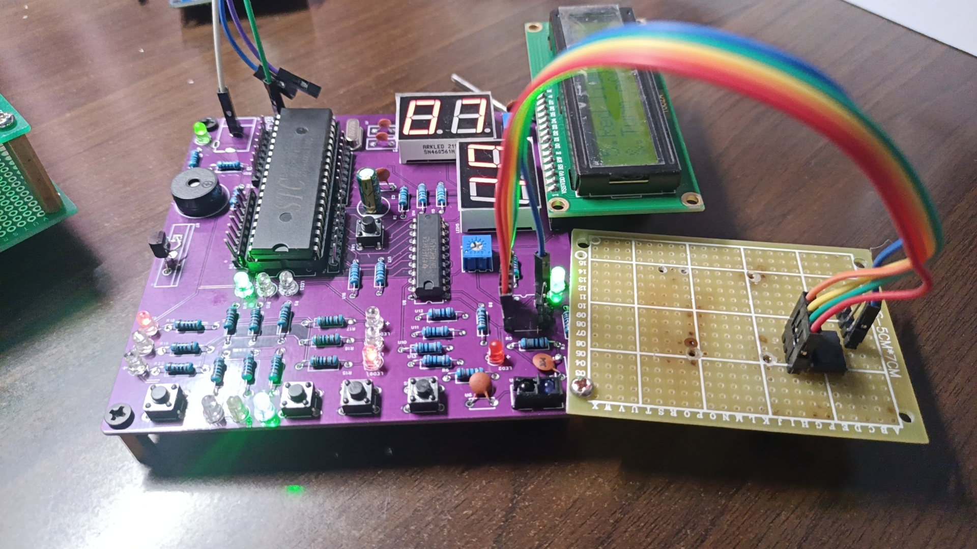
6. Peripherals: Two 0.56-inch common cathode digital tubes, one infrared tracking module, one passive buzzer, one LCD1602; III . Advantages and Features 1. JLCPCB provides free PCB fabrication, 100mm*100mm; 2. Complete debugging interfaces, all pins are brought out for easy testing and secondary development, can be used as a core board; 3. Uses DC interface or header power supply; 4. Affordable price, complete functionality; 5. Uses high-quality JLCPCB PCBs and genuine components to ensure product quality; 6. Almost all components are through-hole (except for two capacitors and transistors, all are through-hole; surface mount technology can be used to reduce area); IV. Circuit Analysis Diagram 4.1 Traffic Light System Schematic Diagram IV. Physical Verification Scheme Breadboard Verification Board Making Physical Image Finished Product Image Due to incorrect component selection, flying wires appeared, which have been corrected. The scheme has been successfully verified. Since the source code is borrowed from someone else, it will not be uploaded here. If needed, you can contact me privately for it, or refer to my desktop clock. The idea behind this code is optimized from that.
BOM_Board1_PCB1_2023-07-02.xlsx
Altium-based Traffic Light System (based on 51 Microcontroller) - 2023-11-04.zip
PDF_Traffic Light System Based on 51 Microcontroller.zip
Altium-based Traffic Light System (based on 51 Microcontroller).zip
PADS_Traffic Light System Based on 51 Microcontroller.zip
BOM_Traffic Light System Based on 51 Microcontroller.xlsx
97296
electronic
 The top part is the original board, and the bottom part is the upgraded board.
 lower left corner is the button area, with four buttons for function selection, an encoder for speed adjustment, KEY1 and KEY2 being + and - buttons for function selection, KEY3 for trigger source selection (T1 or T2), and KEY4 for DAC output. The encoder is used to adjust values; for example, when the selection box is in the S position (the yellow box position), the trigger voltage can be adjusted.
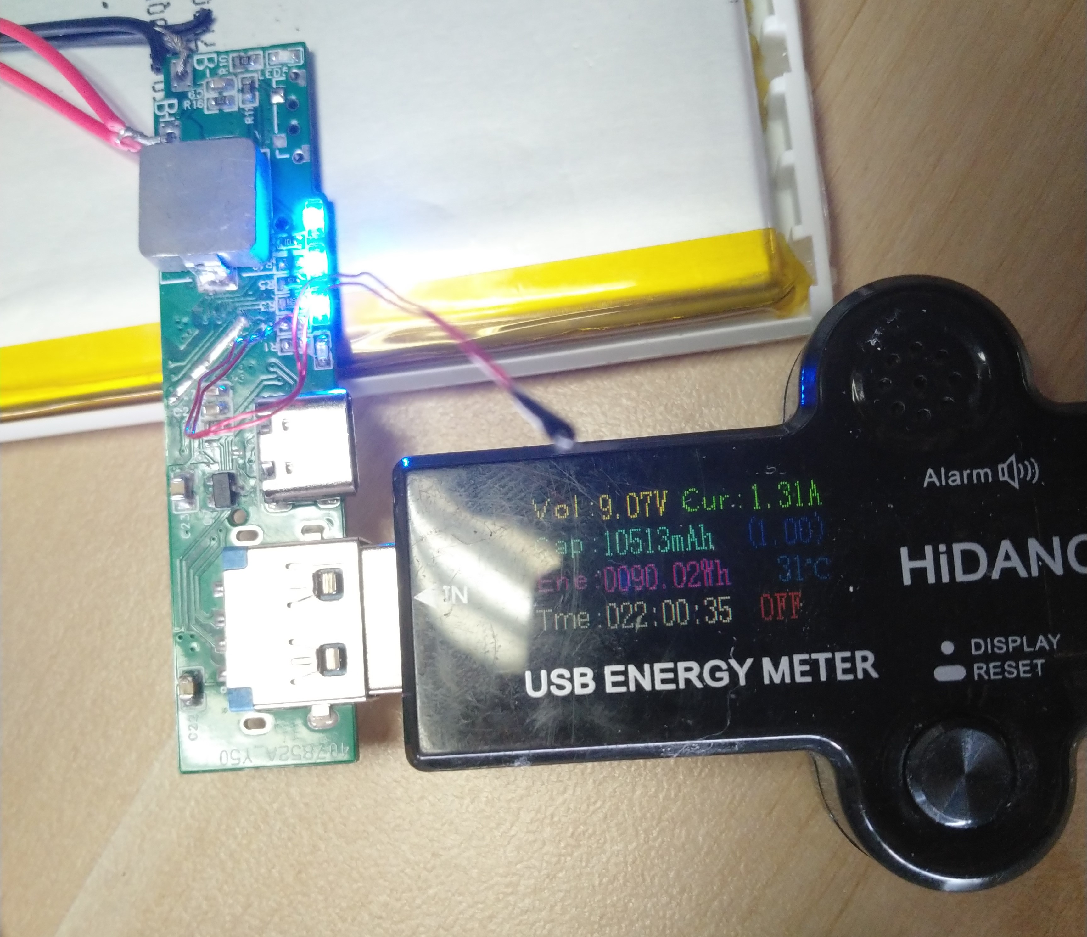
 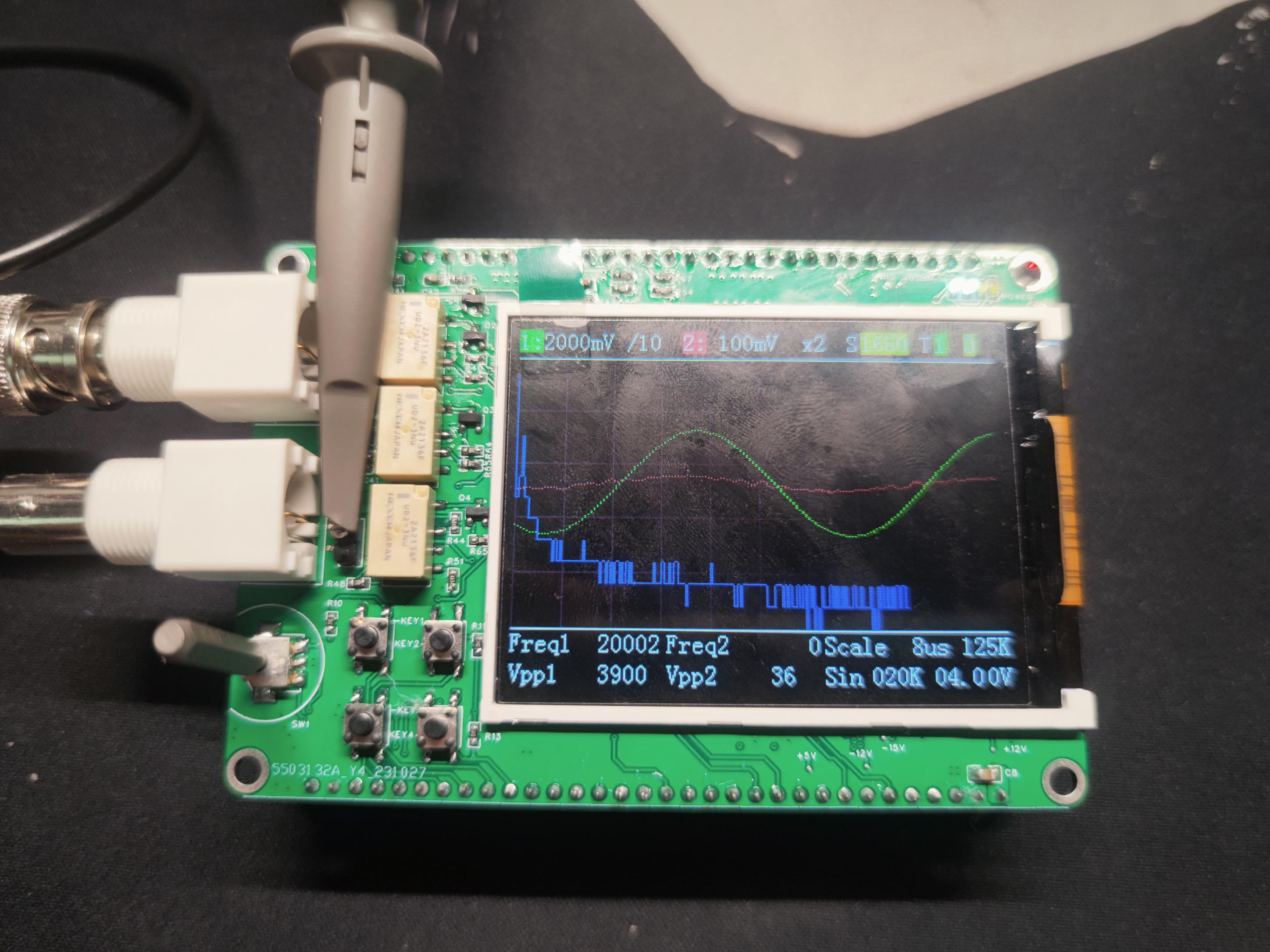 The side has a TYPE-C interface and buttons, with the buttons connecting to the IP5306 for controlling the battery boost output.
 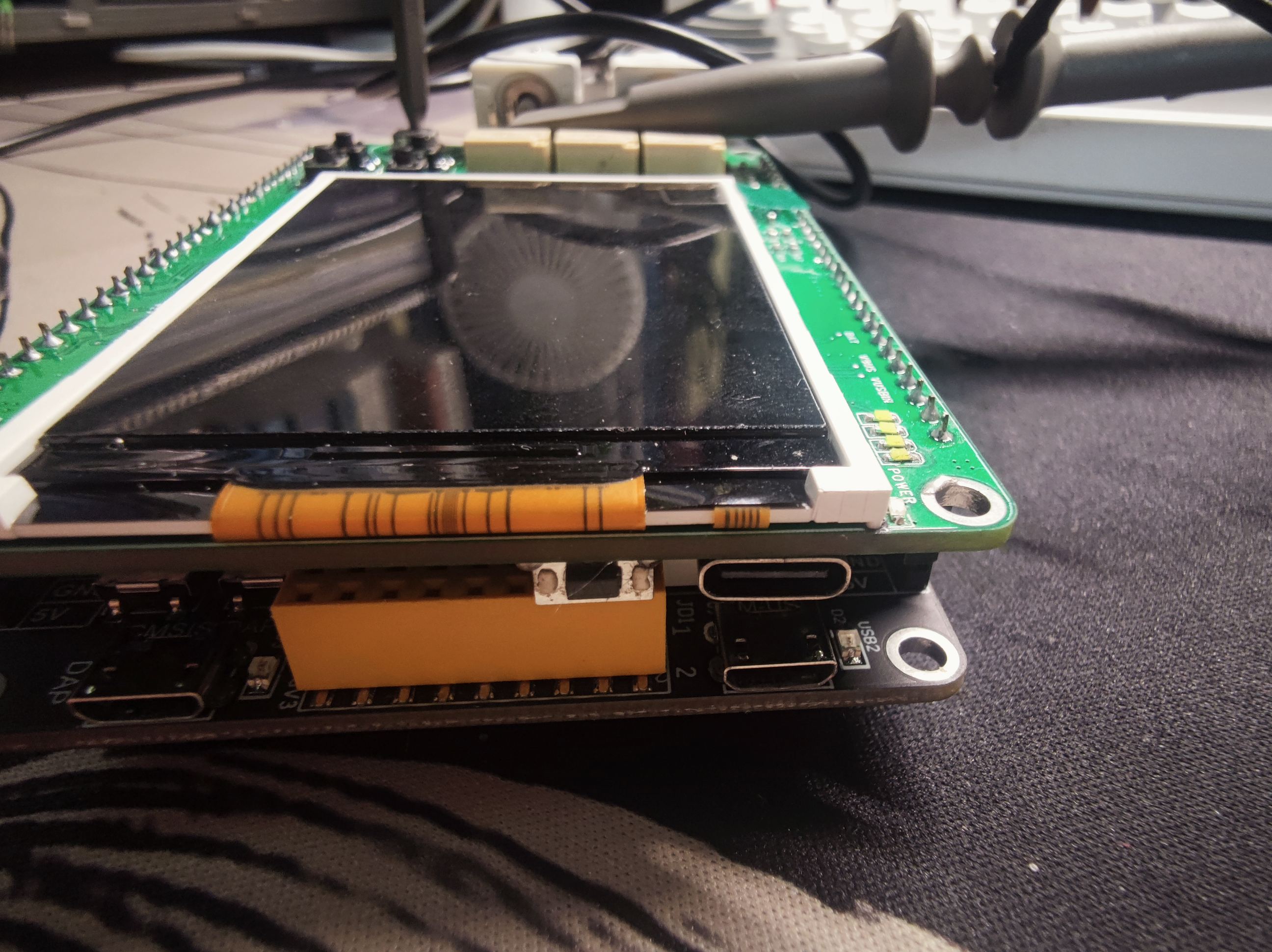 Four LEDs above the screen on the front display the battery level.
 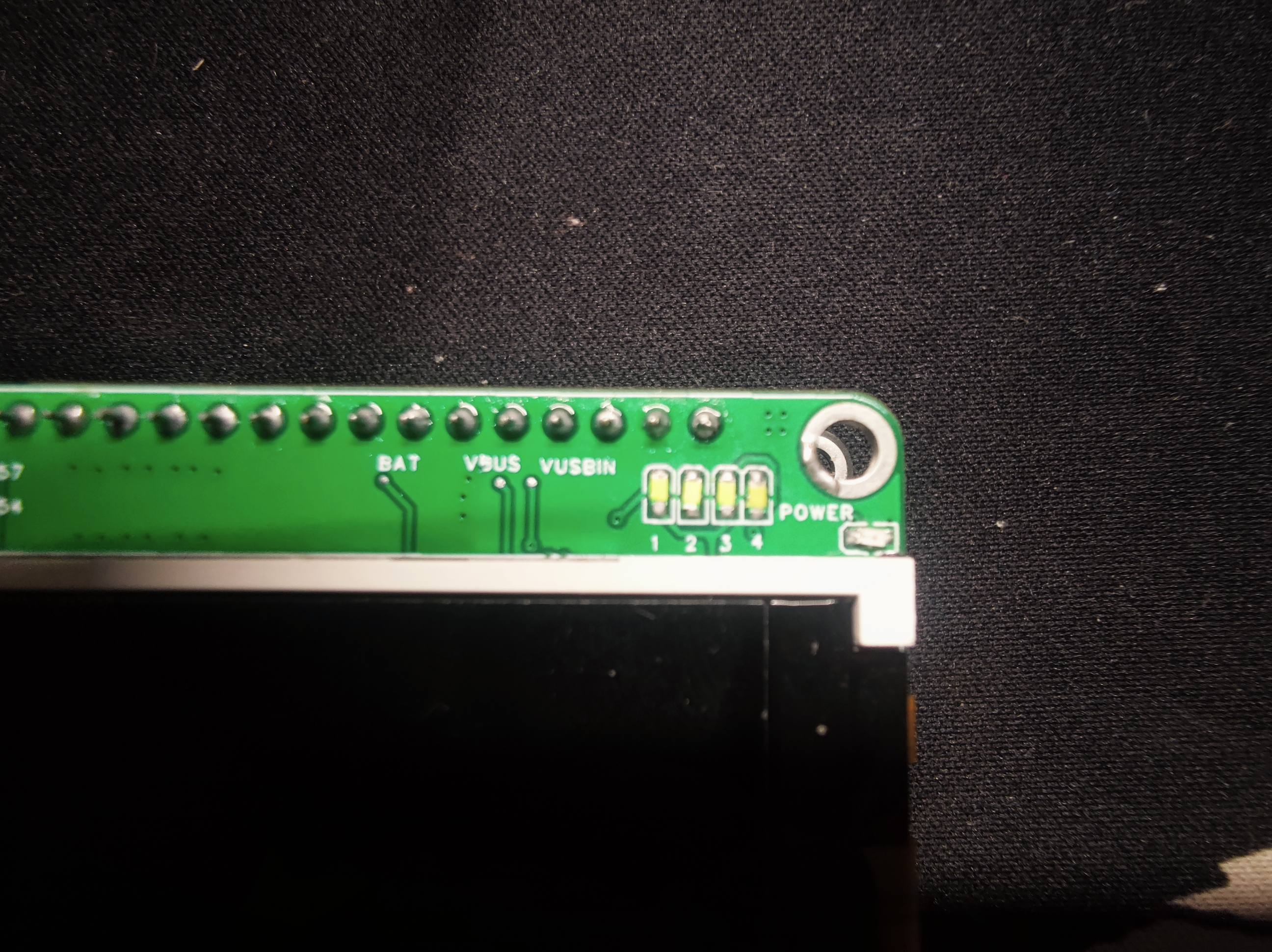 Several key voltage test points have been added to the front for easy debugging.
 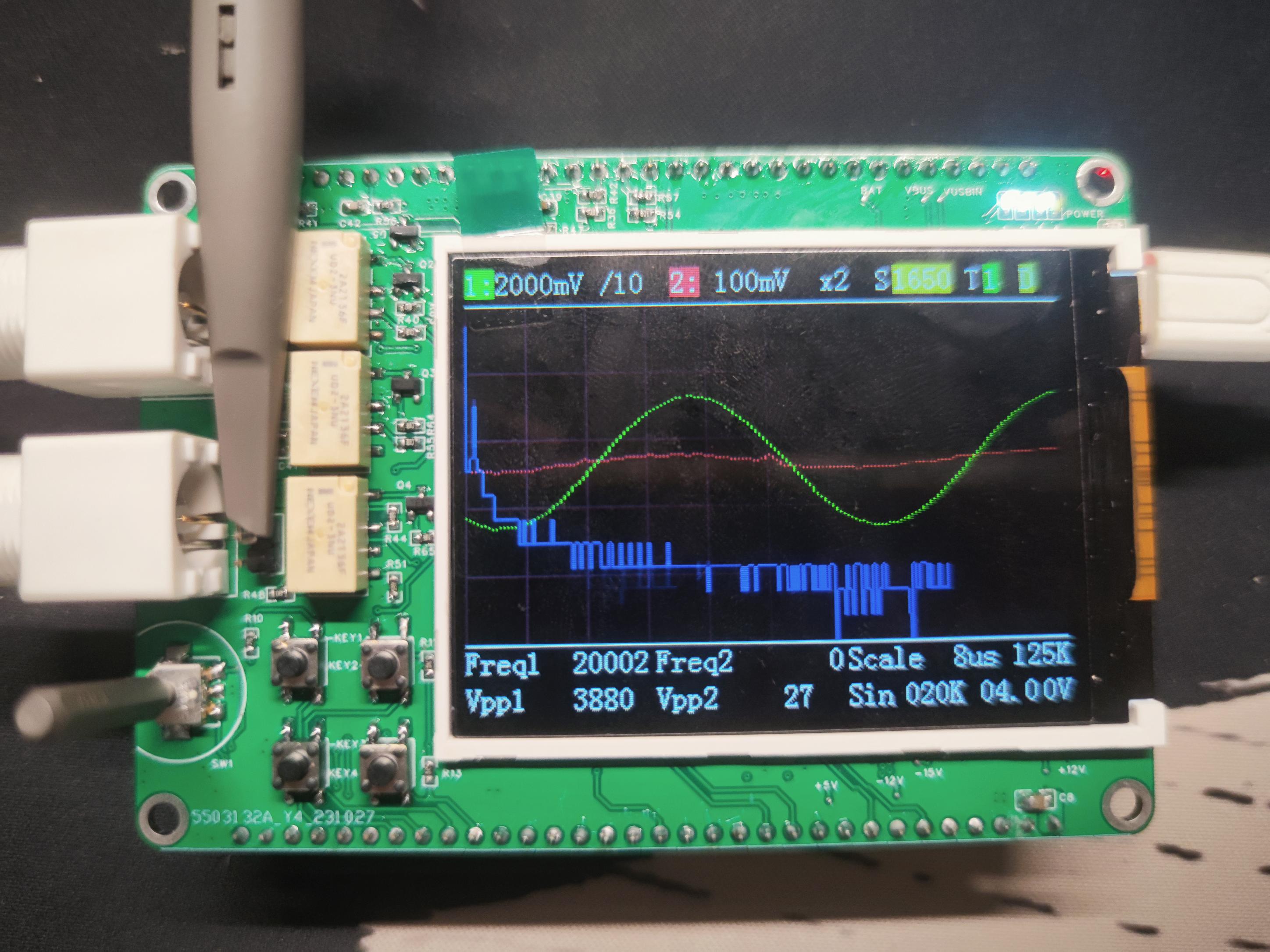 square, and
 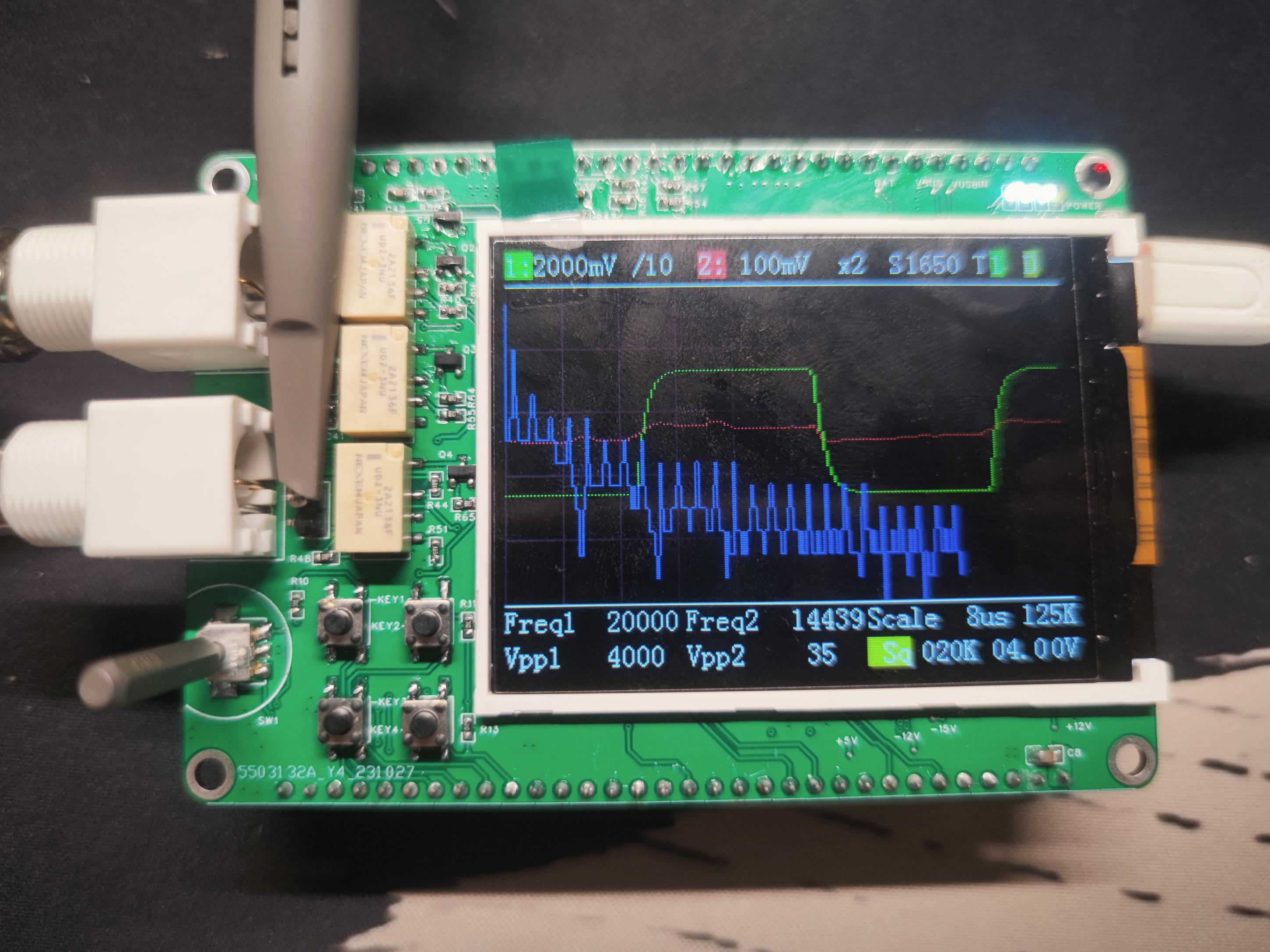 triangle waves.
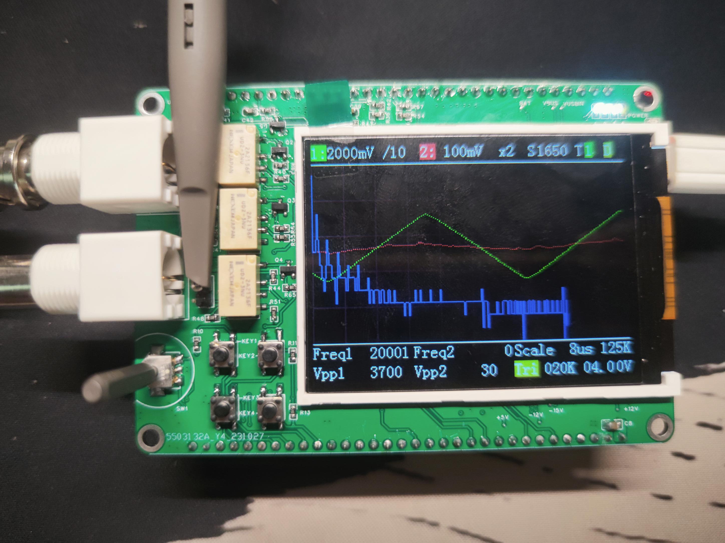
 an input voltage of 11.93V and an output voltage of 4.978V, AC coupled. See the image below for details.
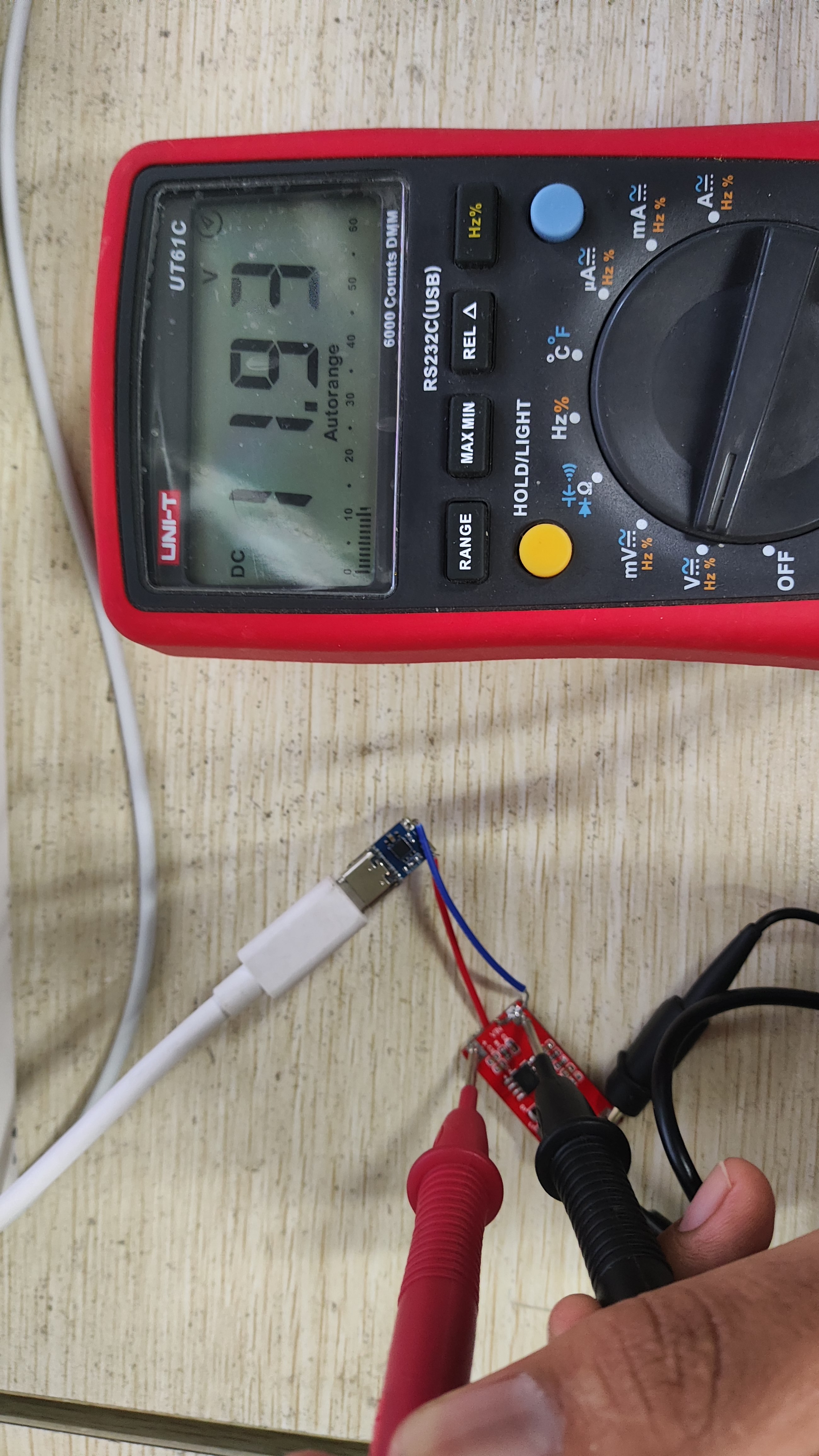


 京公网安备 11010802033920号

 CRCW12183K24FKB4AP


