In this training camp, I designed a versatile and playable core board/development board based on the STC32G12K128. Onboard components include LED/KEY/RGB/BLE 5.0/SPI common pinout sockets (accommodating most SPI modules, especially OLED expansion)/IIC common pinout sockets (accommodating most IIC module access expansion)/TF card module/XGZP68 series absolute pressure sensor module/passive buzzer, etc. Additionally, it features an external VREF selectable switch (2.4999V and 3.3V), as well as selectable switches for offline battery power and fast discharge during low power consumption.
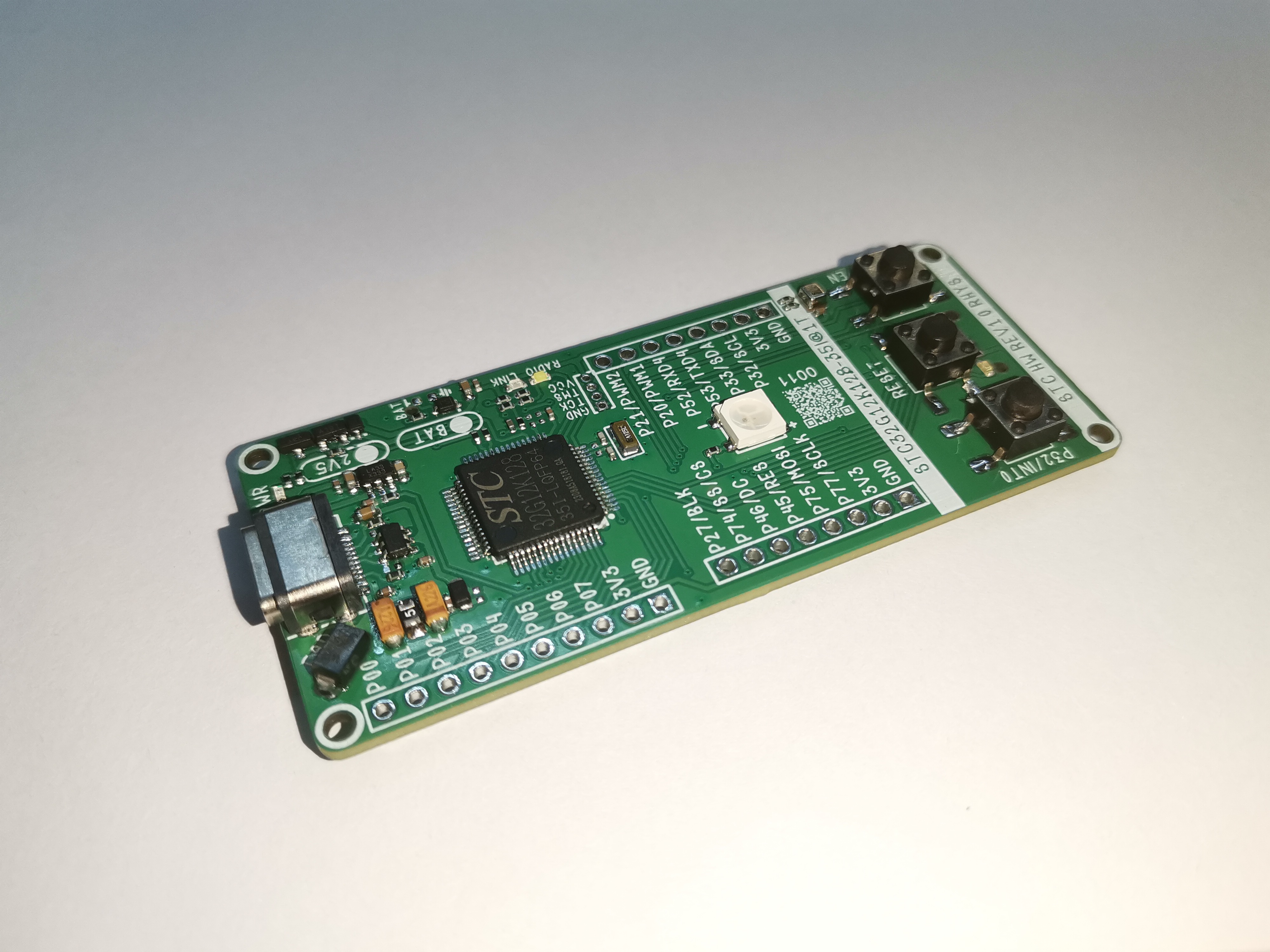
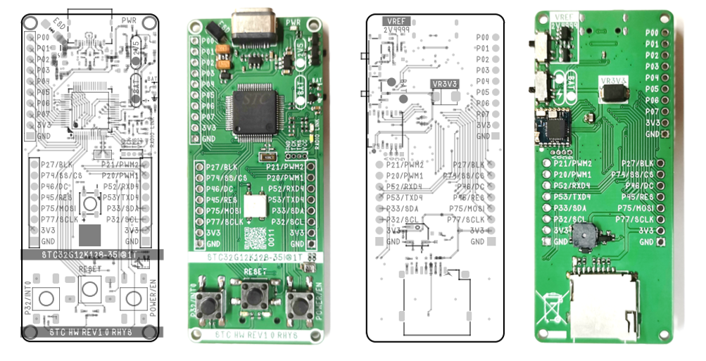
The design of related modules is shown in the following diagram:

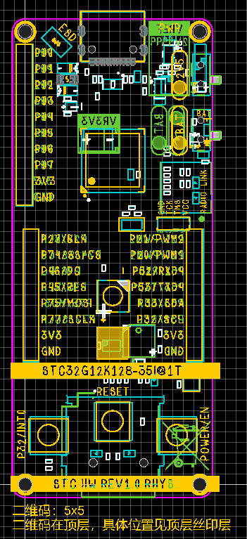
Due to the compact core board design and limited space, only the most commonly used P0 port is brought out. The peripherals and some pin functions related to the P0 port are also marked in the diagram above.
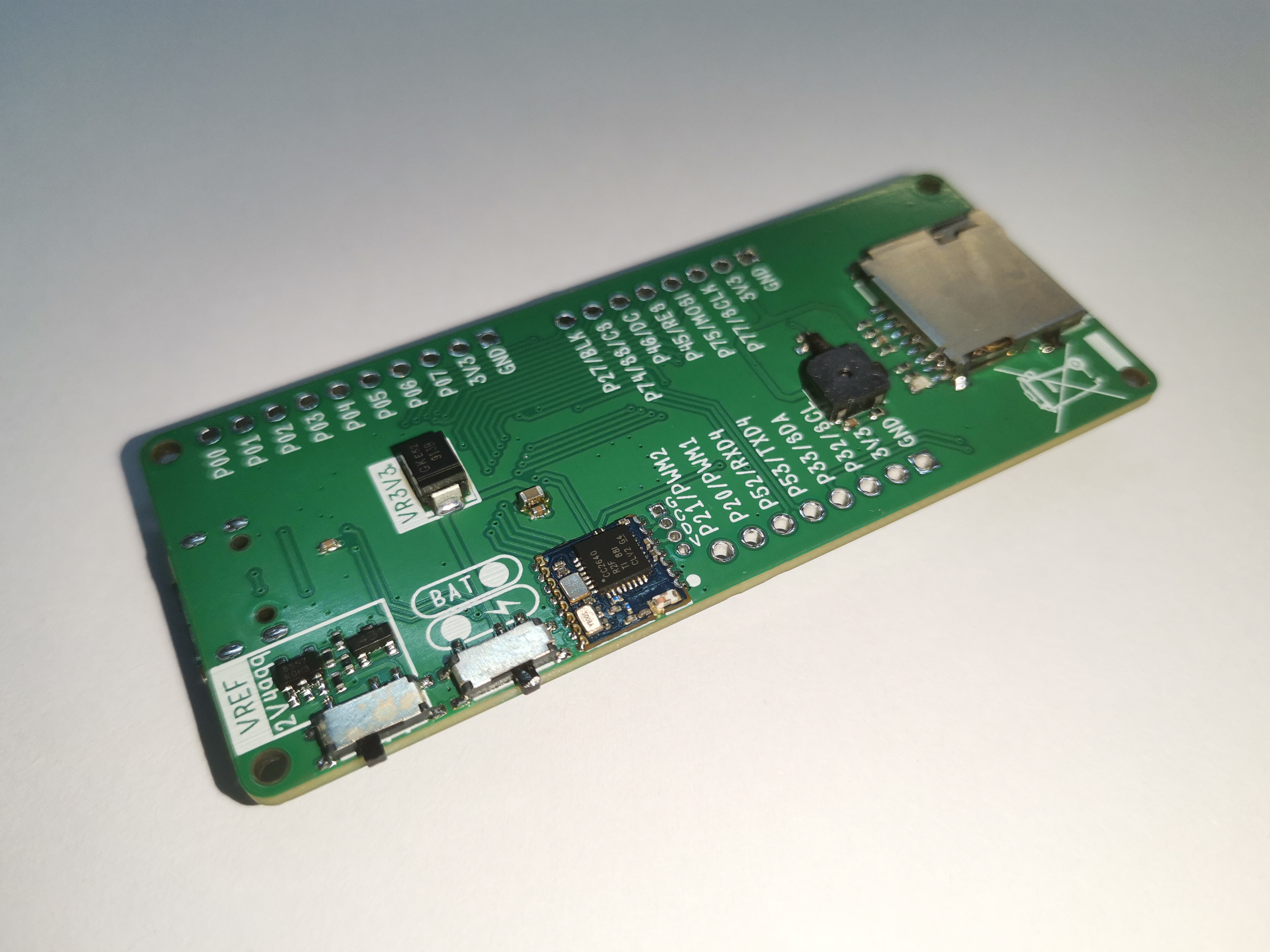
I. Physical Demonstration
II. Appearance Design
As a development board, it should have the functions of enlightenment and rapid application; this is the core functional requirement.
Design Point 1: Therefore, it is necessary to bring out one or more sets of GPIO ports. Positioned as a simple, entry-level, compact core board, therefore 1-2 sets are selected here;
Design point 2: Onboard program download module, a core board with both download and programming functions can make it more convenient for users without needing too much "stationery"—I must add that this is self-deprecating, not directed at anyone here. Because I'm a poor student, and I have a ton of stationery;
Design point 3: Type-C port, keeping up with the trend!
Design point 4: Maximize the aggregation of core board elements to maximize the performance of STC32G12K128;
Design point 5: Include interactive elements such as LEDs and keys;
Design point 6: Ability to develop general-purpose devices and module expansions (such as OLED modules, sensor modules, etc.) (common peripherals SPI/IIC/USART/PWM, etc.);
Design point 7: Looks cool;
Design point 8: The core board should have layout guidelines, follow general specifications for system circuitry, and add ESD protection circuits to facilitate direct CV by secondary development engineers;
but I want it to be ordinary, yet extraordinary. This might seem contradictory, but upon consideration, it's not. Therefore, the following design point is added:
Design Point 9: This board itself can be used to complete a project directly without needing to connect any modules or cables.
The author envisions creating a water-related project:
[Underwater pressure detection at a depth of 3m~5m]. Please note that this wasn't specifically developed for anglers.
This project requires several things: (1) data acquisition (2) data storage (3) offline power
supply. The list of
requirements
and countermeasures for
pressure data acquisition,
absolute pressure sensor (XGZP68 series) ,
data storage
BLE 5.0 or TF card offline storage,
offline power supply,
battery power supply interface.
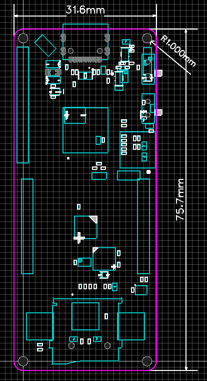
Based on the above design points, after the author made a simple layout and estimation of the components, the following outline can be obtained
(maybe you all feel that it looks like a Mazda 6, but in fact the initial draft only has a 30x75 frame and four d=2mm positioning holes. It was adjusted version after version... Let me tell you, the initial draft is not actually this. The initial draft has been sent. Finally, I will give you a surprise.)
III. Schematic Design
(1) Chip core and peripheral design [The circuit part necessary for the chip to work normally]
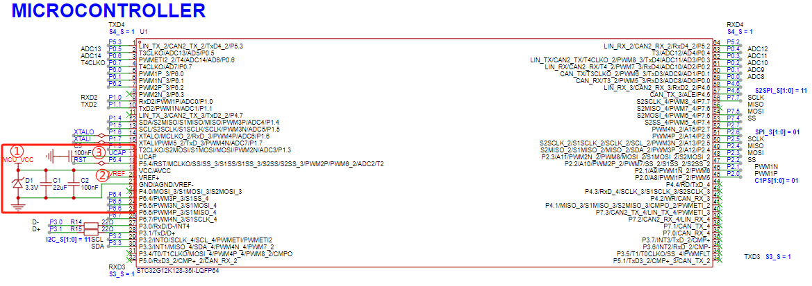
On June 18, 2024, under the temptation of 1000 yuan, I read the STC datasheet for 2 days and summarized one thing: for the STC chip to work normally, it only needs (taking STC32G12K128-35I-LQFP64 as an example)
Essential elements for STC chip operation (minimum requirements)
No.
Description
①
Power supply pin PIN19 is connected to 1.9V~5.5V voltage, power supply pin PIN21 is connected to GND
②
VREF+ pin PIN20 is either connected to VCC and pin19 (shared pin), or connected to the reference power supply. Chips with this pin cannot leave it floating
③
UCAP pin PIN17 is connected to a 100nF decoupling capacitor to GND.
It's that simple!
(2) Circuit for direct USB hardware download [One chip can download and run programs at the same time]
It's also that 1000 yuan. After studying the manual, I found that the STC chip hardware USB direct program download process is extremely simple:
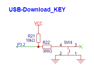
When the P3.2 port is low, power the MCU and directly enter the USB download mode, waiting for the program to be burned.
① Design a button circuit to pull low P3.2 port:
② Select an LDO chip with EN pin, and use the button to control the MCU power enable:

[Download program steps: Press and hold P3.2_KEY, press POWER_SW_KEY, release POWER_SW_KEY, and enter USB download mode]
(3) TYPE-C input circuit design and ESD related design:
① Note that TYPE-C is required for USB communication, so at least a 16-pin TYPE-C interface is required. The ESD of the USB line is a general 2-channel ESD (USBLC6-2SC6). In order to adapt to TYPE-C power supply, CC1 and CC2 need to be grounded through 5.1k resistors respectively.
In order to adapt to the possibility of not soldering ESD chip to save costs, two 22R resistors are placed here. R10 and R11 are used to replace the ESD chip (choose 1 of 2)
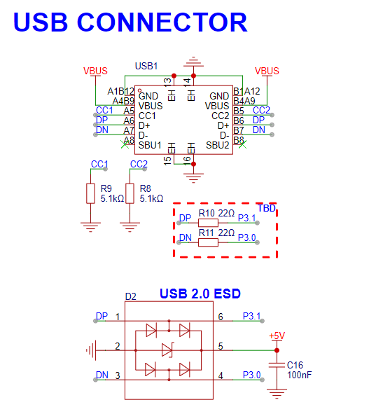
② Perform TVs surge suppression and simple filtering on the input power supply

(4) Perform interactive LED, KEY, BEEP
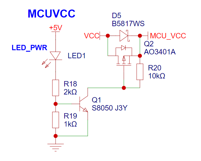
① Power indicator light: This design references the schematic of the STC8051U University Project Experiment Box V1.0, using an NPN+P-MOS scheme to control the MCU power enable and provide a power indicator light to inform the user that the system is connected to +5V.
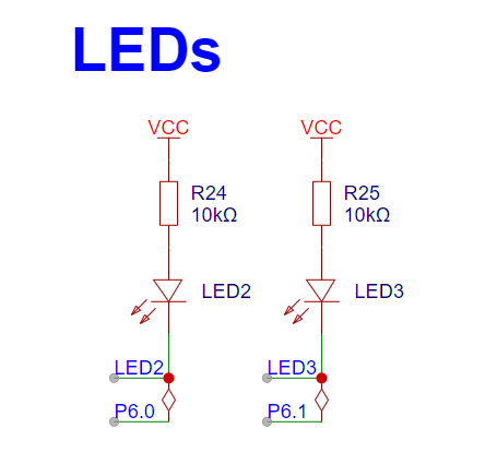
② LEDs: These are not randomly selected. P6.0 and P6.1, in addition to GPIO functions, can also be mapped to PWM peripherals. PWM can be used for LED lighting later. A boon for LED lighting engineers.
③ PWM lighting is here! An RGB LED is placed in the center of the board – a symbol of superhuman light.

④ Due to board space constraints, only one more key can be placed in the same width. P5.4 is chosen, as it can be mapped to the RST function. [R16 and C17 are optional soldering and generally unnecessary, as STC has integrated the external reset into the chip, resulting in an extremely minimalist peripheral design!] 】:

⑤ Add a buzzer, a passive buzzer, driven by PWM:

(5) VREF and BAT interface design
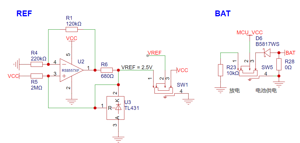
This VREF circuit was designed by a master, but the designer is unknown. However, you can come to this post to appreciate the master's analysis:
A very ingenious high-precision voltage reference circuit by micespring
To save current, you can directly refer to the following formula:
V_U2_PIN1 = 2.495/220K*(220K+120K) = 3.86V
I_431 = (VCC-2.495)/2M + (3.86-2.495)/680
(ignoring 2M) I_431 = (3.86-2.495)/680 = 0.002A = 2mA = The optimal current value according to the 431 datasheet
assumes that for every 1V change in VCC, the operating current of the 431 changes by 1/R7 = 0.0000005A = 0.5uA. This is less than 1 microamp. The 431 always operates at a constant current of 2mA, regardless of changes in VCC, ensuring a consistently stable reference voltage output.
The battery circuit interface will not be described in detail. Simply put, it uses a 0603 package to solder the positive and negative terminals of the battery.
To avoid conflict between the battery and the LDO power supply, a Schottky diode is used here, along with the Schottky diode above, to select the MCU power supply.
(6) External crystal oscillator: make a simple external low-speed crystal oscillator to improve the accuracy of the RTC in harsh environments using an external clock source.

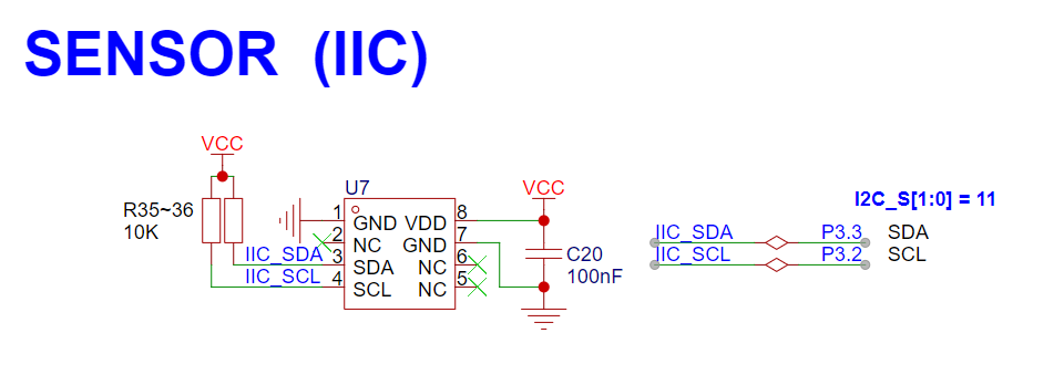
(7) Absolute pressure sensor module: IIC communication.
(8) BLE 5.0 Bluetooth: mainly uses the pass-through function (RF-BM-4044B4, if necessary, directly develop the CC2460 chip and retain the secondary development interface).

(9) TF card module: use the SPI protocol (note to retain the pull-up resistors for each port; in fact, the STC chip can be set up/down separately).

(10) Finally, make a pin header expansion, commonly using SPI sorting and IIC sorting. For symmetry, pull up 2 PWM pins and pull up 1 serial port:
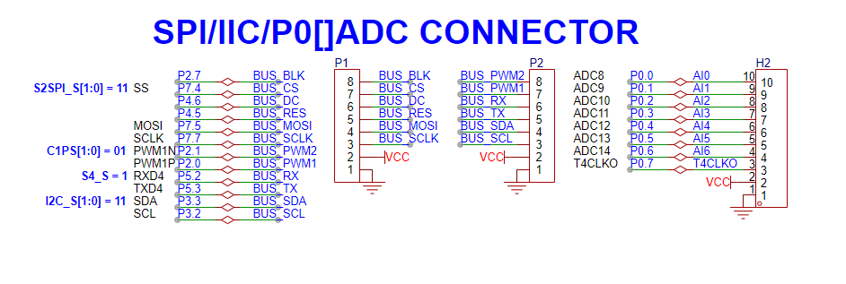
take a look at the complete figure

. 4. PCB design:
the next step is the layout work, 100 words omitted here.
(1) The basic shape has been designed in the early stage, and the layout of the main components has been properly arranged. The layout work is mainly... (100 words omitted here);
(2) Design silk screen - important. Silk screen cover the important functions, especially the interface part, and expand the interface with text function descriptions to facilitate users to compare and use and expand other modules!
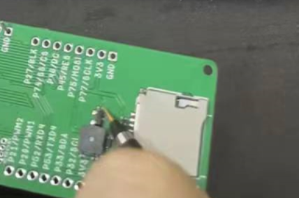
V. Soldering and assembly
Anyway, I have finished soldering, so I can say loudly: I can do it with my hands!
Note: If you have not finished soldering, just follow the traditional technique of soldering the surface mount first, and then soldering the buttons... It is not difficult, so I will not explain it in detail.
VI. Voltage node test of some circuit modules
(1) After soldering the power supply part, test whether VCC and GND are short-circuited, and then connect TYPE-C to test whether the LDO output is ≈3.3V;

(2) After soldering the VREF part, test whether VCC and GND are short-circuited, and then connect TYPE-C to test whether the LDO output is ≈2.495V;

(3) After soldering all, test whether VCC and GND are short-circuited, and then connect TYPE-C to test other routines!
VII. Core Board Routine/Program Design
(1) GPIO_Lighting
Master is online. Since this is the first project, I will explain in great detail how to use the environment and program. If you only need the routine or know how to compile and download the program, you can skip this section. [This section is verbose]
① First look at the hardware. The functions of the three LEDs in the hardware: PWR_LED lights up when inserted into TYPE-C, which serves as a power indicator;
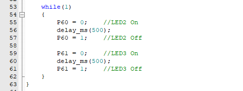
LED2 and LED3 are located at the bottom of the core board and are driven by low level (in layman's terms, the LED lights up when it is low level, and turns off when it is not low level).
[If you forgot the diagram, scroll the wheel to the third chapter (4) above to find it]
② Create a KEIL 5 MDK project with STC32G12K128 as the core:
Select the core

magic wand and set the chip Memory Model. Select "Produce HEX file" for XSmall (official recommended mode)
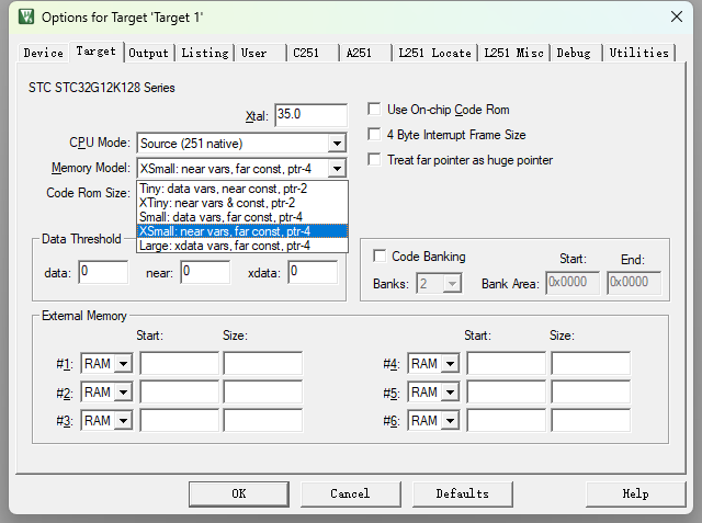
and set the specific format of HEX (HEX-386).

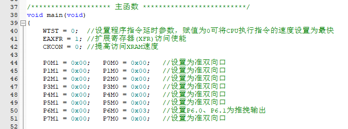
Create a .C text file as main.c (the program will be written here) (note the header file reference).

Set P6.0 and P6.1 to push-pull output mode (learn to read the manual).

Write the logic (LED2 and LED3 blink alternately, blinking interval 500ms).
Perform

the preparatory work before compilation and download.


③ Observe the experimental phenomenon
(2) INT0_KEY
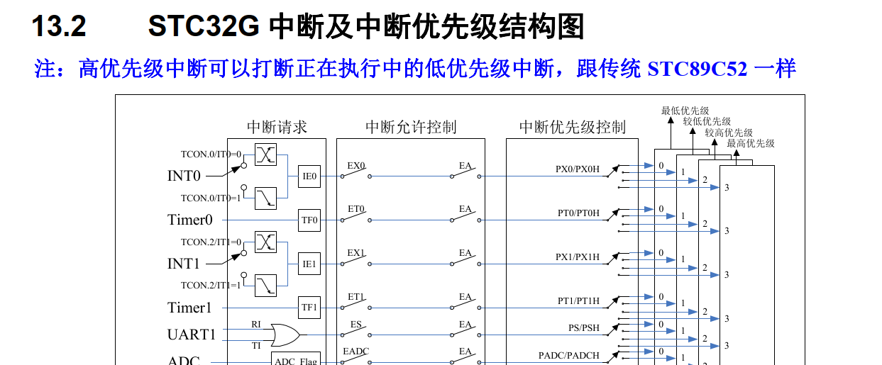
interrupt, as the name suggests, if an interrupt signal is given (if the interrupt signal priority is higher than the current work), the current behavior must be paused to execute the corresponding interrupt service.
In STC32G12K128, taking INT0 as an example:
INT0 related register operation
register
description
IE0
external interrupt 0 flag
EX0
INT0 enable bit
IT0
trigger edge (1: falling edge) (0: rising/falling edge)
EA
global interrupt enable bit
Initialize related parameters according to register description

Write interrupt service function

Write event trigger

Observe experimental phenomena

(3) PWM_BEEP
Understand the passive buzzer driving method:
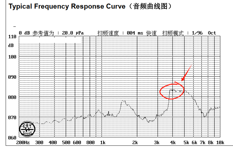
From the datasheet, it can be seen that when the buzzer driving frequency reaches the resonance frequency @4kHz, the sound pressure reaches the maximum value, which is about 83dB (the specific resonance frequency and maximum sound pressure decibels can be found in the datasheet of the selected device).

The commonly used driving method is shown in the author's schematic diagram, or the following figure:
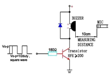
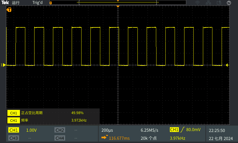
So the core work of this routine is to program a 4KHz PWM waveform with a duty cycle of 50% to make the buzzer BB
open the datasheet and look up the PWM frequency calculation method:
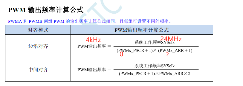
Assuming the working frequency is 24MHz, without frequency division, then the theoretical calculation is:
PWMx_ARR = (24MHz / 4kHz) - 1 = 5999

Set duty cycle

initialization PWM related
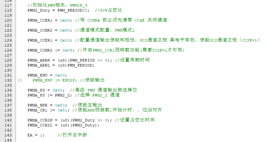
logic can be written [Preset use button INT0 to switch the buzzer state: when the buzzer sounds, the two LEDs light up; when the buzzer is silent, the two LEDs turn off]
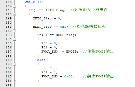
Note: The initialization of LEDs and INT0 is described in detail in the previous example, so it is omitted here (it is actually written in the example) to avoid too much redundancy.
Observe the experimental phenomenon
(4) TIM0_timer
interrupt timing trigger event is a basic course for microcontroller applications, often used in various automatic programs, and has a wide range of application scenarios.

Taking TIM0 as an example, establish a project and complete the task of triggering the event by timing 1 second:
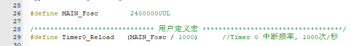
This time, first establish the logic (timed interrupt once every 1ms, then 1000 interrupts trigger the event task: the task is to flip the level of LED2 and LED3 to achieve alternating on and off)

supplement the timer 0 initialization and timer 0 interrupt service function (directly refer to the official library function)
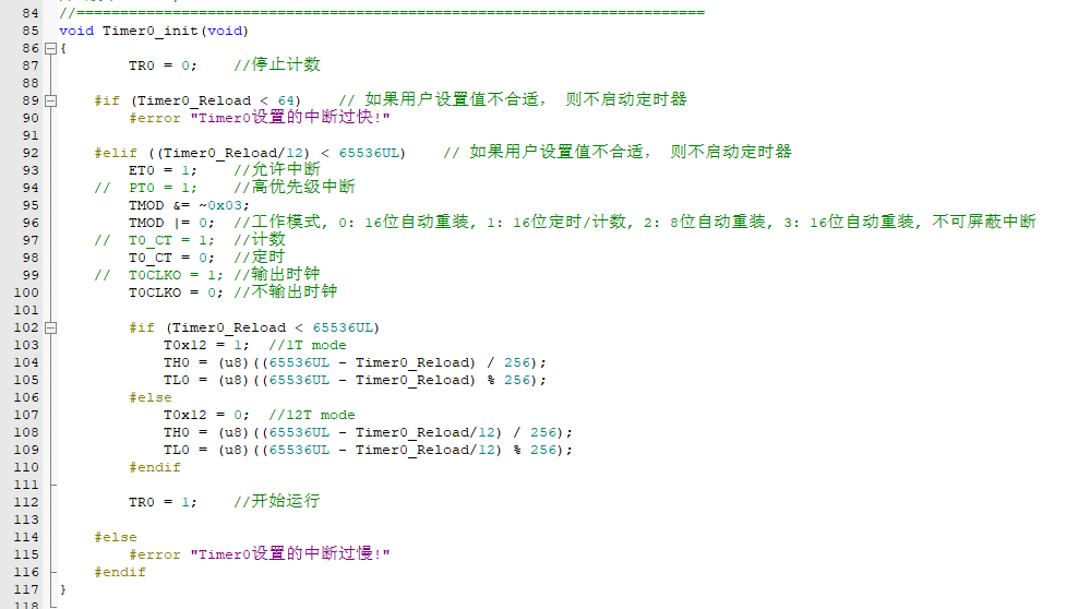
in the 1ms interrupt function, set the 1ms flag to high, return to the main function for processing

and observe the experimental phenomenon

(5) USB_HID_DEBUG
In the author's design drawings, TYPE-C is directly connected to the internal USB of STC32G12K128, so the API provided by STC can be used to print the USB-HID protocol for program-type serial port debugging.
You need to use the "stc_usb_hid_32g.LIB" library file provided by STC to easily use the USB interface for data communication:
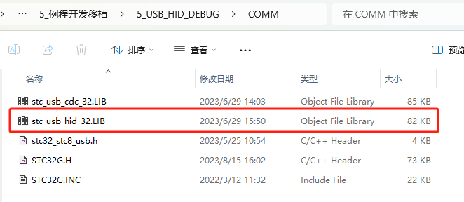
Add the library to the project:

Call the STC API according to the STC-USB-HID specification:
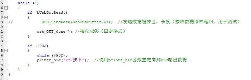
Add the necessary program:

Add USB receive judgment and response instructions in the main loop and write a simple P32 button trigger:
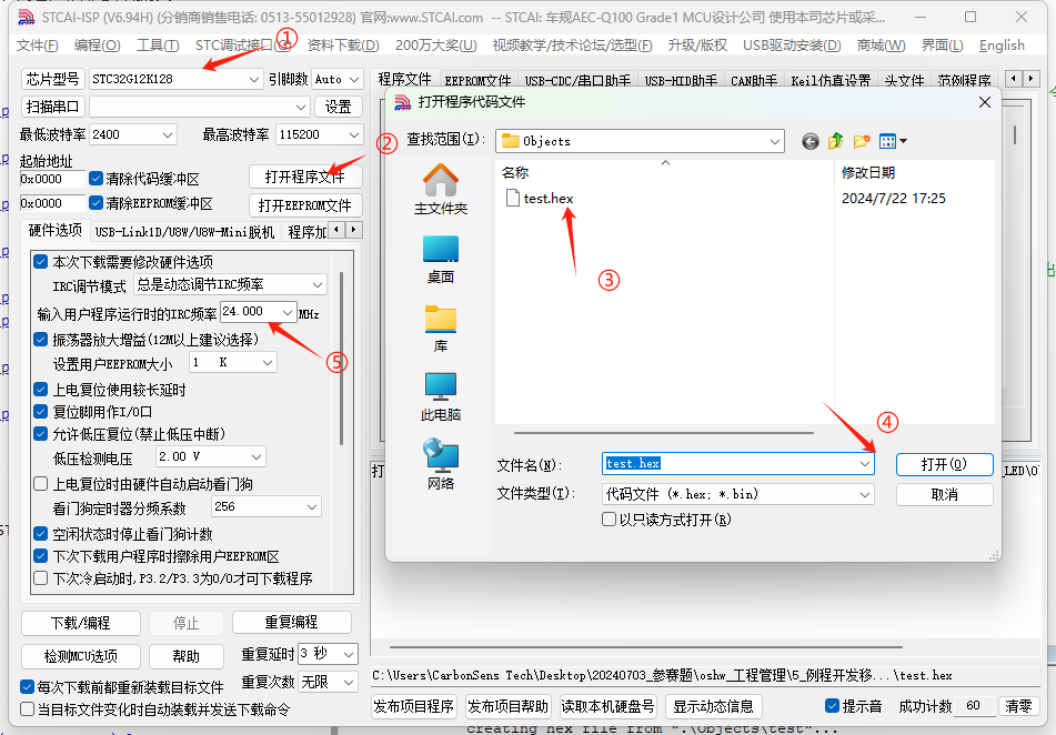
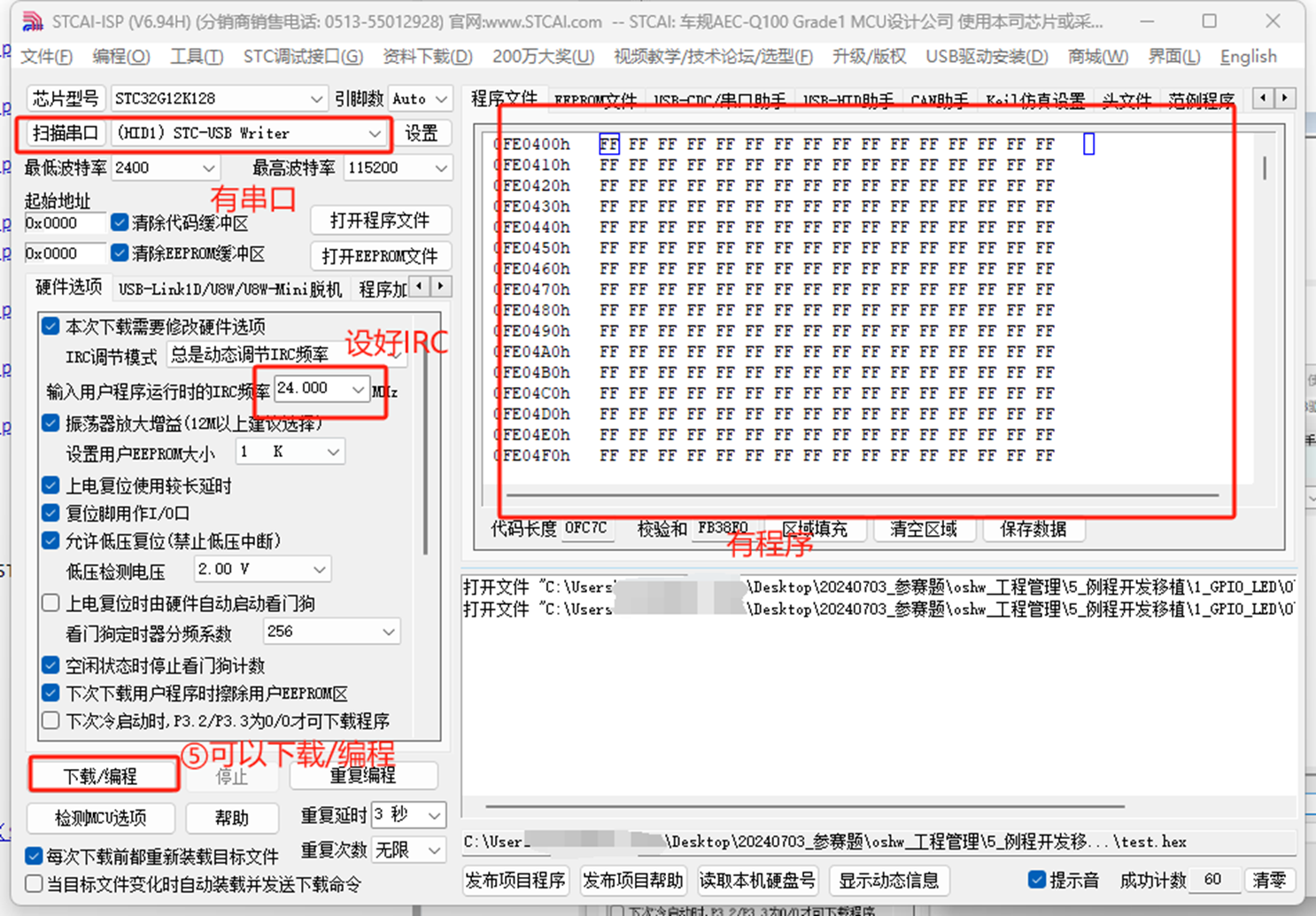
In the STCAI-ISP tool, set the operation as shown in the figure:

Press the P32/INT0 button to trigger printing:

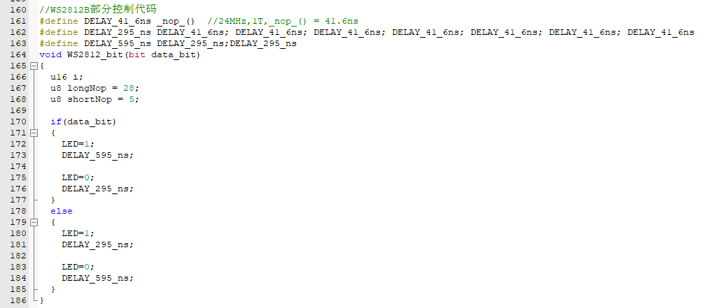
(6) BIT_WS2812B
I was careless and miscalculated. This MCU does not have DMA direct transmission to PWM, but it is not a big problem. We will use the traditional function!
First, understand the decoding protocol of WS2812B: 24-bit (RGB 888) data transmission. Each WS2812B in the daisy chain intercepts 24 bits and then passes the data to the next chip at a speed not exceeding 800KHz.
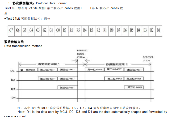
Regarding 0 and 1 codes, according to the input code pattern diagram, a high TOL percentage in one cycle corresponds to code 0, and vice versa for code 1.

The minimum code period is 0.89us, and typical code pattern times are shown in the table below.

For an I/O port, it should first be set to a quasi-bidirectional port or push-pull output (recommended). For code 0, it needs to be set high + a small delay + set low + a large delay to meet the code 0 time requirement. Similarly, for code 1, it needs to be set high + a large delay + set low + a small delay to meet the code 1 time requirement.
For delays in the microsecond (µs) range, using the `nop()` instruction: NOP instruction execution time = 1/systemCLK * 1T.
Assuming a clock frequency of 24MHz, the time for one NOP instruction is approximately 0.0416µs. We create a table to facilitate the construction of instructions that meet these time requirements:
WS2812B Code Table µs
High Level
Low Level /
1 Code
0.595µs
0.295µs
0 Code
0.295µs
0.595µs
WS2812B Code Table NOP MIN
High Level
Low Level
1 Code
0.55
/0.0416 = 13.22 0.2/0.0416 = 4.80
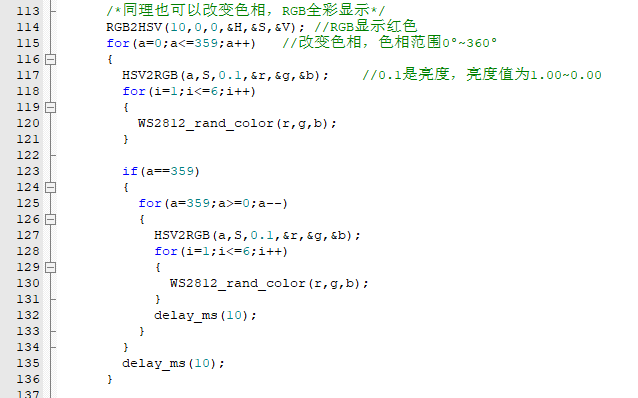
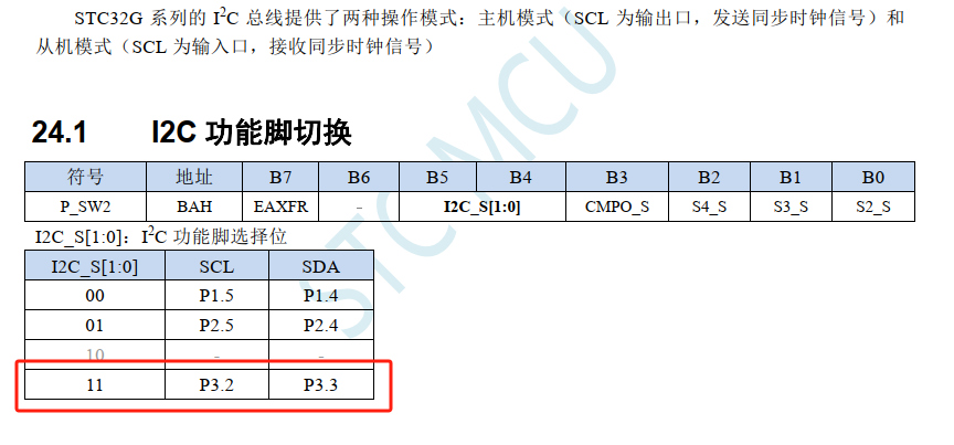
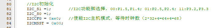
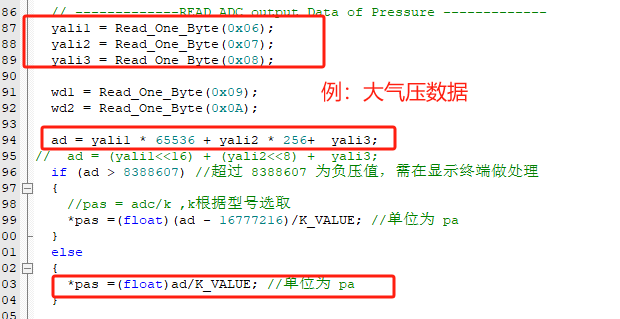
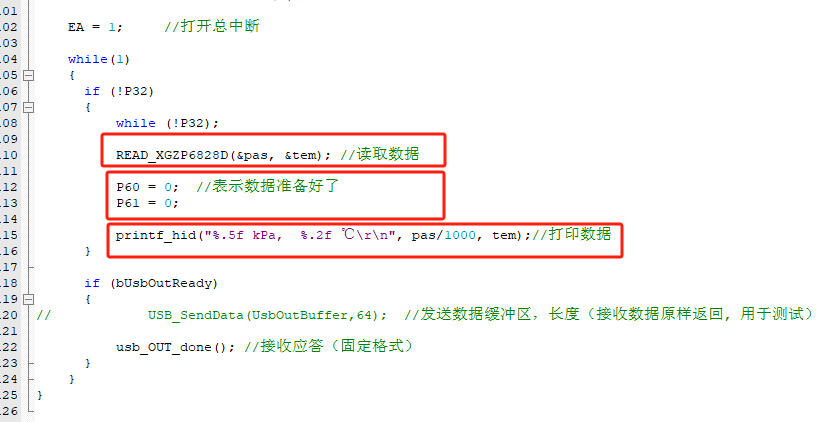
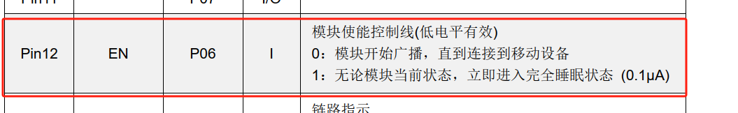
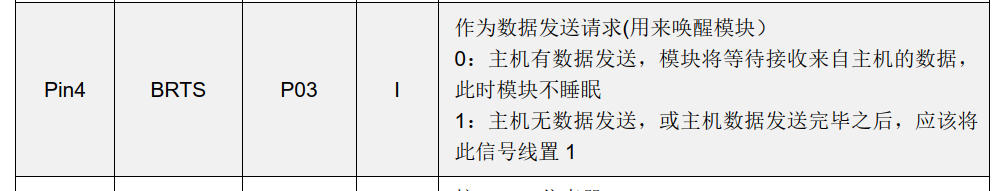
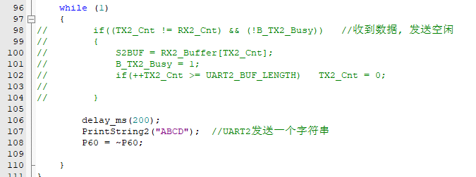
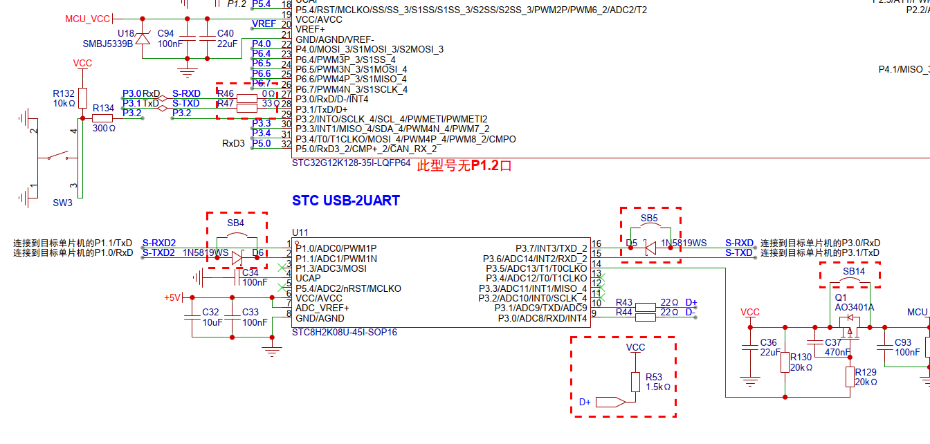
0 Code 0.2/0.0416 = 4.80 0.55/0.0416 = 13.22 WS2812B Code Table NOP typical High Level Low Level 1 Code 0.595/0.0416 = 14.3 0.295/0.0416 = 7.09 0 code 0.295/0.0416 = 7.09 0.595/0.0416 = 14.3 WS2812B code table NOP MAX high level low level 1 code 1.2/0.0416 = 28.84 0.35/0.0416 = 8.41 0 code 0.35/0.0416 = 8.41 1.2/0.0416 = 28.84 Write into function for later use: Write two application programs: monochrome breathing light: rainbow breathing light: Observe experimental phenomena (only rainbow) (7) IIC_XGZP68 STC32G hardware IIC needs to be switched to the corresponding pin. The author uses P3.2 and P3.3 group: When the host mode is also needed, pay attention to setting the corresponding IIC pin as a quasi-bidirectional port, especially SCL, which is the output mode. Since the external pull-up resistor was soldered, it was configured as an open-drain output. For IIC communication, the module's IIC address needs to be known, which can be found in the datasheet. Note that the address needs to be left-aligned and conforms to the standard 8-bit IIC communication protocol. The model used is XGZP6828D. Register list: In this list, we can see that reading 0x06, 0x07, and 0x08 retrieves atmospheric pressure measurement data; reading 0x09 and 0x0A retrieves temperature measurement data. Data is aligned and converted according to MSB, CSB, and LSB. Refer to the datasheet for the calculation formula. Similarly, temperature data is converted in the same way. Use the USB_HID from the previous chapter for data printing debugging: In the program, first read the data, then light up the indicator, and then output the printed data to observe the experimental phenomenon (8) BLE_USART mainly uses the pass-through function. In the schematic diagram, the author connects the BLE module to the P1.0 and P1.1 ports: S2_S needs to be set to 0, and the mapping pin BLE needs to set the EN pin to 0 to enable the module so that its Bluetooth module can be connected to the mobile phone . BRTS also needs to be set to 0, only when there is data to be sent. In the program, set USART2 to: 115200 baud rate, interrupt enable, and receive enable: Write a simple pass-through verification program to send "ABCD" at regular intervals: Observe the experimental phenomenon (this is a large one, refer to the appendix file) (9) Single board project, project construction ideas: https://www.bilibili.com/video/BV17B8qeqECN/ VIII. Appendix [Appendix 1] STC IDE MDK environment installation instructions


Note: KEIL MDK 5 and the C251 compilation environment need to be installed. The header files for the STC series chips must be imported into KEIL MDK 5 using the STCAI-ISP V6.94H tool before the relevant example programs can be used.
Download addresses:
STCAI-ISP V6.94H Full Version,
STCAI-ISP V6.94H Simplified Version.
[Appendix 2] Related Datasheets :
The related datasheets are included in the example programs in PDF format.
[Appendix 3] Example/Program Design References
: Note: Most of the example programs in this open-source project are rewritten based on official example programs. Download address: STC Official Library Functions (STC32G12K128)
. [Appendix 4] Initial Draft Bonus: The initial draft's
layout, resembling the UNO-R4-WIFI version of the Charlie Light Array and MEGA2560, is quite cool, but it exceeds the length limit, so it's been submitted.

The initial draft uses STC32G12K128 + STC8H2K08U for full-function implementation. This article's open-source PCB design has at least two sets of I/O ports removed.
------------------End of Article-------------------------------------------------------END--LINE-----
Related files can be found in the attachments. Give it a like if you enjoyed it!


 京公网安备 11010802033920号

 1.5KE120/53


