Project Description:
Modbus-RTU 8-channel analog signal acquisition unit, 16-bit resolution, independent range settings for each channel.
Ranges: 0~20mA/4~20mA, -150~150mV, -500~500mV, -1~1V, 0~2.5V, -5~5V, 0~10V, -10~10V.
9~36V voltage input, interface is anti-static, surge-proof, and lightning-proof.
Supports two-wire/three-wire/four-wire sensor wiring.
Voltage/current ranges are switched via DIP switches.
The host computer testing software can receive and display the acquired data. Must include the JLCPCB EDA logo.
Open source license
: GPL 3.0.
Project Attributes:
This project is being publicly disclosed for the first time and is my original work. This project has not won any awards in other competitions.
Project Progress
: March 19 - Started drawing schematics; March 23
- Completed schematics and PCB layout;
March 26 - Modified and optimized schematics and PCB layout routing; learned JLCPCB EDA module reuse function;
April 7 - Completed PCB design and board production; applied for consumables; PC-side PY program 90%
complete; April 9 - Debugged program and board;
April 30 - Sheet metal casing prototyping in progress;
May 7 - Received sheet metal casing;
May 17 - Completed integration testing between the microcontroller and host computer;
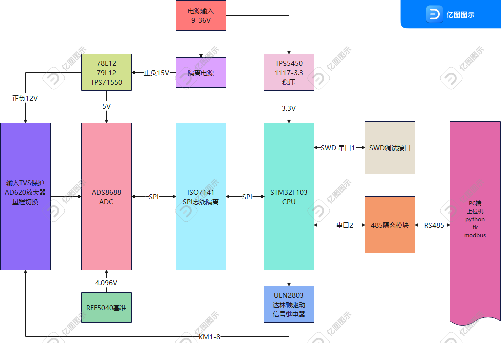
June 5 - Revised schematics and PCB, changed to single-ended input, and updated documentation. System Overall Block Diagram . Hardware Design Principle Explanation:
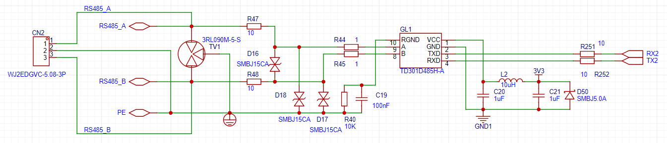
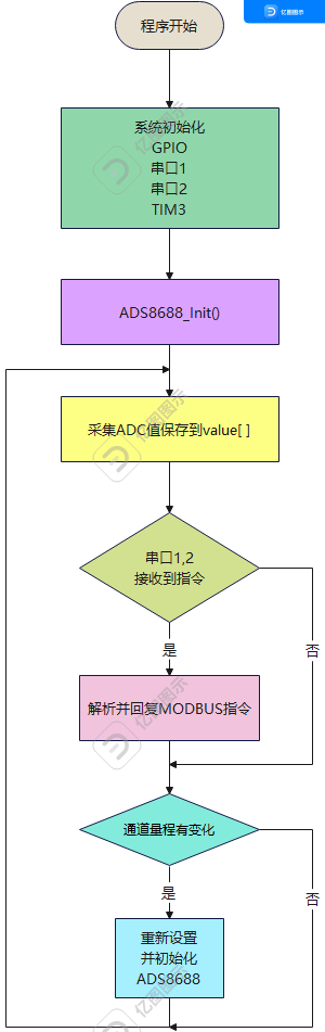
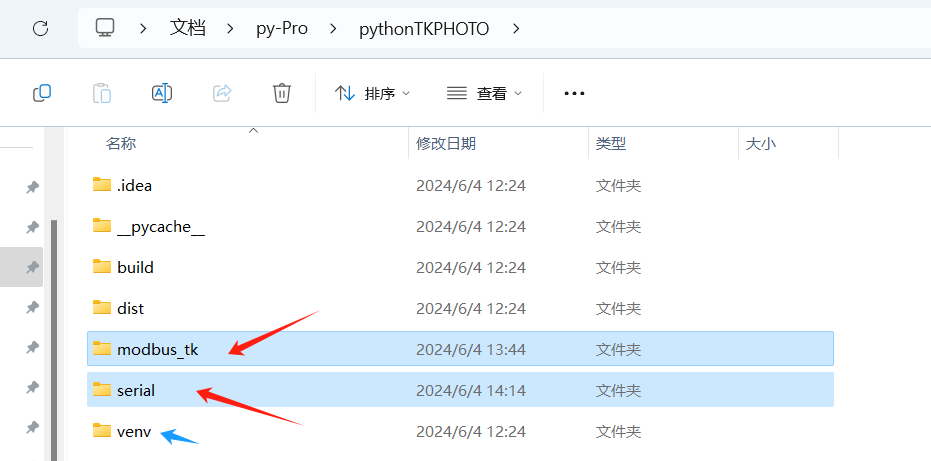
485 uses an isolation module and adds TVS and gas discharge tubes to achieve anti-static, surge, and lightning protection. ADC + Reference Section: ADC selected is ADS8688, a 16-bit ADC supporting pin-to-pin direct replacement of the 18-bit ADS8988. R230=1K, R229=NC. If you want to use an internal reference instead of an external one, R230=NC, R229=1K. A DC 9-36V power supply is input from pins 2 and 3 of P9. One path is stepped down to 5V by a TPS5450, and the 1117-3.3V ripple-reduced supply powers the CPU and 485 module. The other path is isolated by a U21 power supply module, outputting ±15V. A 78L12 or 79L12 linear regulator outputs ± 12V. U13 regulates the voltage to 5V to power the op-amp and ADC module sampling front-end. Project requirements: (0~20mA/4~20mA), (-150~150mV), (-500~500mV), (-1~1V), (0~2.5V), (-5~5V), (0~10V), (-10~10V). The eight range relays are not energized. ADS8688 The measurement range can be set via software. After direct sampling, four DIP switches are added for (0-5.12V), (±5.12V), (0-10.24V), and (±10.24V). Shorting the SW 2-5 cutter heads and connecting a 120-ohm resistor in parallel to the input channel enables the current range of 0~20mA/4~20mA. With the relay closed, adding a DIP switch allows the SW 1-6 cutter heads to switch the AD620's amplification factor, achieving -150~150mV and -500~500mV. Adding a DIP switch to SW... 3-4 Tool Head Switching Single/Dual Polar Signal Software Instructions Microcontroller Acquisition Terminal Flowchart PC Terminal Program Flowchart The PC terminal interface is simple in function and interface. The top left is the logo, the middle left is the serial port settings, the bottom left is the status display, and the right side shows the channel settings and acquisition display . According to the DIP switch, the correct selection is for current or voltage range. Select the appropriate range; unused channels should be "closed". It uses the Modbus-RTU protocol. The default slave address is 0x02, and the baud rate is 115200. 8-channel data register addresses: 0x00-0x07. 8-channel setting register addresses: 0x10-0x17. Physical Demonstration Usage Notes Due to design issues, during testing, please connect all negative terminals of the signals to signal ground using jumpers. The PCB project file has been modified to address this issue; all channels are now changed to single-ended input using DIP switches. Using the host computer software : Step 1: Recommended download: Thonny ( download address: https://thonny.org/) Step 2: Copy the modbus_tk and serial libraries from venvLibsite-packages as shown in step three of the image below. You can then enjoy playing with Python. Design considerations: The DCDC module generates heat; there are 17 operational amplifiers, resulting in excessive power consumption. To achieve low power consumption, a single-channel ADC with an electronic switch can be used for switching. During SMT placement, U13 = TPS71550, C389, C399 = 10uF capacitors. Other STM32 projects: 8CH16BIT.rar //Microcontroller project ; pythonTKPHOTO.rar //Python project; Sheet metal casing: 8ch_asm_asm.zip //Sheet metal casing demonstration video: in the attachments, thank you.


 京公网安备 11010802033920号

 1600BG1G5IPG2UB


