Project Overview:
This project is a radio based on the SC1088 radio integrated chip. It is compact, suitable for students, and can be easily held in one hand. It has low power consumption, requiring only a battery for extended battery life. It boasts a high success rate in manufacturing, is easy to replicate, and has low cost. A potentiometer controls volume, and a push-button switch controls FM radio
functionality
. To use the FM radio, plug in headphones, connect the power, and press the search button (SCAN). The circuit automatically searches for radio stations from low to high frequencies. It automatically stops searching when it receives an FM radio station. To change stations, press the search button again. When the highest FM receiving frequency is reached, simply press the reset button (RESET). The radio frequency will drop back to the lowest end, and the search will restart, searching for higher frequencies.
The FM radio uses the SC1088 integrated circuit, which is a 16-pin dual-in-line flat package (surface mount). The typical operating voltage is 3V. In addition to the complete functions of FM radio reception from antenna to frequency discrimination output audio signal, the circuit also has a search tuning circuit, signal detection circuit, squelch circuit, and frequency phase-locked loop circuit for compressing intermediate frequency deviation. The
theoretical receiving frequency range is 88-108MHz.
Principle analysis (hardware description):
The intermediate frequency of the SC1088 circuit is designed to be 70KHz. The external circuit does not use an intermediate frequency transformer. The intermediate frequency selection is accomplished by the internal RC intermediate frequency filter. The radio uses the headphone cable as the antenna. The FM signal induced by the headphone cable enters the mixer circuit from pin (11) of the SC1088 integrated circuit. After mixing with the local oscillator, a 70KHz intermediate frequency signal is generated. The oscillation frequency of the circuit is determined by L1, C5 and D1 (varactor diode). In this circuit, the voltage controlling the varactor diode D1 is provided by pin 16 of IC1. When the search switch (SCAN) SW2 is pressed, the RS flip-flop inside IC1 turns on the constant current source, charging capacitor C9 through pin 16. The voltage across C9 continuously rises, the capacitance of D1 continuously changes, and the frequency of the local oscillator circuit composed of D1, C5, and L1 continuously changes for tuning. When a radio signal is received, the signal detection circuit causes the RS flip-flop inside IC1 to flip, the constant current source stops charging C9, and under the action of the AFC circuit, the frequency of the received broadcast program is locked, thus ensuring stable reception of radio broadcasts until SW2 is pressed again to start a new search. When the reset switch (RESET) SW1 is pressed, capacitor C9 discharges, and the local oscillator frequency returns to its lowest point. The active components and resistors of the intermediate frequency amplification, limiting, and frequency discrimination circuits are all inside ICI. The FM radio signal and the local oscillator circuit signal are mixed in the mixer within IC1 to generate a 70kHz intermediate frequency (IF) signal. After passing through an internal 1dB amplifier and an IF limiter, the signal is sent to a frequency discriminator to detect the audio signal. After internal loop filtering, the audio signal is output from pin 2. In the circuit, C1 at pin 1 is the squelch capacitor, C3 at pin 3 is the AF (audio) loop filter capacitor, C6 at pin 6 is the IF feedback capacitor, C7 at pin 7 is the low-pass capacitor, C8 between pins 8 and 9 is the IF coupling capacitor, C44 at pin 10 is the low-pass capacitor for the limiter, C11 at pin 13 is the offset voltage capacitor for the IF limiter, and C10 is the high-frequency filter capacitor.
Since the power required for headphone reception is relatively low, a simple transistor amplifier circuit is used. The audio signal output from pin 2 is adjusted by potentiometer RP and then coupled through C15 to a Class A amplifier composed of a composite transistor (VT1 and VT2). Coils L2 and L3 are RF and audio isolation coils. C17 is a DC filter capacitor.
Note that
the inductor coil in the BOM uses a 5.5T plug-in
. After assembly, adjust the spacing of the oscillating coil L1, which is to adjust its inductance, to change the frequency range. A larger inductance (smaller inter-turn distance) results in a lower frequency, and a smaller inductance (larger inter-turn distance) results in a higher frequency. Carefully adjust repeatedly to make the frequency range of the FM radio station 88-108MHz. After
welding
, the 3D printed button is first embedded into the acrylic panel, then the screws are tightened,
and finally the 3D printed rotary switch is embedded into the potentiometer.
M25 double-pass copper pillars, M22+3 single-pass copper pillars, and M225 screws are used (links: https://item.taobao.com/item.htm?id=23323512894, https://item.taobao.com/item.htm?id=23319408443, https://item.taobao.com/item.htm?id=723800733050). [Actual product image]

Button v1.0.stl
Knob v1.1.stl
3D Printing Alternative Steel Mesh Model File.obj
Physical Product Display.mp4
PDF_Mini Card-Style Electronic Tuning FM Radio Based on SC1088 (Line Dog).zip
Altium_SC1088-based Mini Card-Style Electronic Tuning FM Radio (Line Dog).zip
PADS_SC1088-based Mini Card-type Electric Tuning FM Radio (Line Dog).zip
BOM_Mini Card-Style Electronic Tuning FM Radio Based on SC1088 (Line Dog).xlsx
90768
[Open Source] Home Clock That Never Needs Battery Changes - With Cable
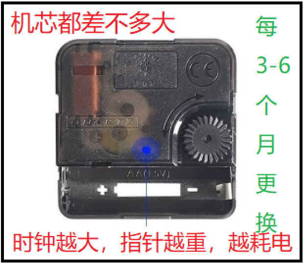
Electronic clocks are too small and uncomfortable to look at, while quartz clocks are more comfortable to look at. However, quartz clocks consume a lot of power, and the larger they are, the faster they drain the battery. They generally need a battery replacement every 3-6 months, and occasionally the clock will stop without your knowledge, leading to being late for work or forgetting to cook. This project designs a module to ensure that the quartz clock never runs out of power.
Overview: I always find electronic clocks at home too small, with mediocre display quality. I have to strain my eyes to see the time clearly, which is uncomfortable. Also, electronic clocks usually use Arabic numerals and either a 24-hour or 12-hour system. I'm not saying they're bad, but I've always used quartz clocks at home, and I'm not used to them. I find quartz clocks the most comfortable to look at—they're large, don't have the strange color pollution of LED lights, and I can easily tell the approximate time with a quick glance. I don't need precise time; precise time always gives me anxiety and a sense of oppression. I live in the countryside and enjoy this relaxed, free-flowing feeling of time.

Current Situation: Quartz clocks are widely available in supermarkets, convenience stores, and general stores, in various sizes, but they all use dry cell batteries, which need to be replaced every few months.
Optimization: This project designs a simple, inexpensive module that allows quartz clocks to operate without maintenance, providing continuous power. This allows users to enjoy the visual appeal of a large clock while eliminating maintenance and hassle.

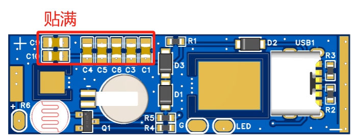
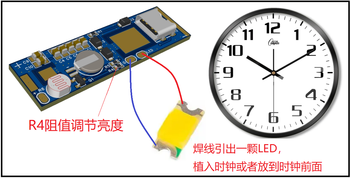
Implementation: After receiving the board, remove the two squares in the middle for later use. Then solder the components, and solder the two squares to their respective ends, with the smaller one at the top (positive) and the larger one at the bottom (negative).

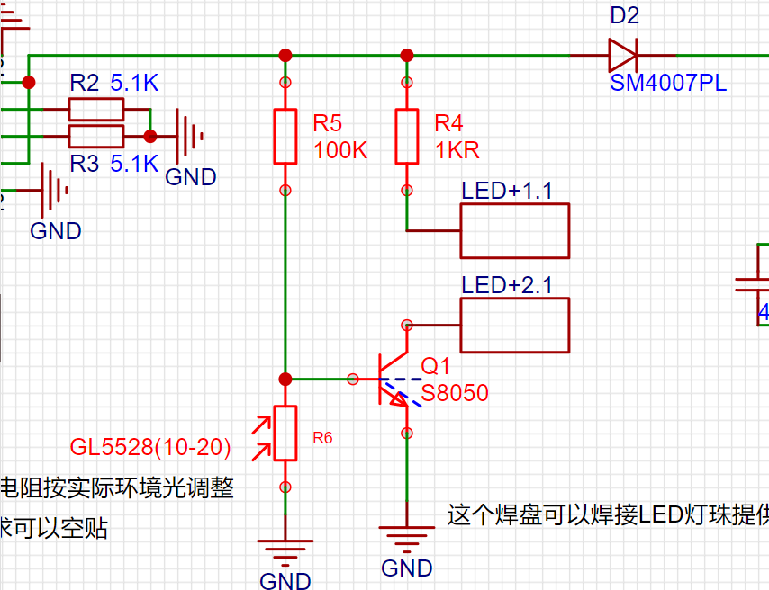
Optional 1: Components as shown in the diagram. If lighting is not needed, they can be left unattached.
Optional 2: If there is no supercapacitor, multiple ceramic capacitors can be used as a substitute, but the power-off time may be shorter.
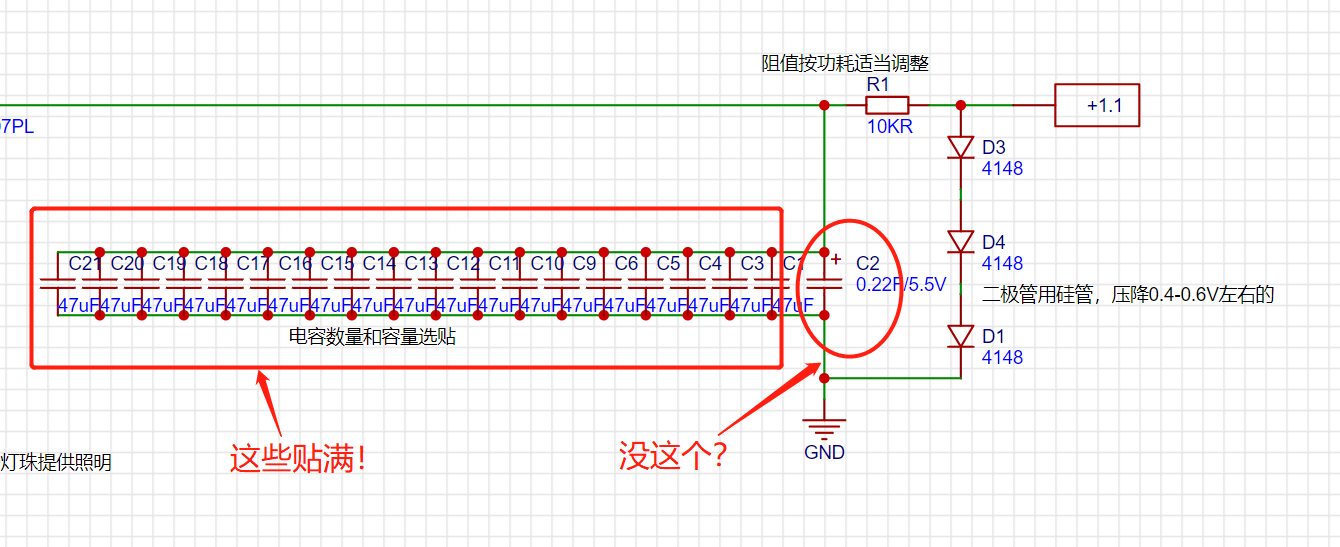
The purpose of these capacitors and supercapacitors is to ensure the clock can continue to operate normally even during short power outages, avoiding the need for time recalibration.
Lighting Arrangement: Solder the lighting as shown in the diagram. Note that the photoresistor should face outwards inside the mainboard mechanism.

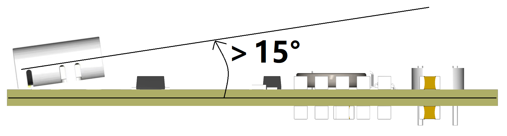
TYPE-C Soldering Precautions: When soldering the socket, ensure it is slightly tilted to facilitate insertion of the TYPE-C charging cable.
Usage: Finally, find a 5V 200mA or higher power adapter and a TYPE-C charging cable. Continuously plug the power supply into the mains to power the quartz clock. For a neater look, find a wall socket to hide the power adapter and charging cable.

Video Description: [This is the clock you should have at home; add one item and it'll be maintenance-free for life! - Bilibili] https://b23.tv/9UiRh0z
Test automatic light on/off.mp4
Test Output Voltage.mp4
PDF_【Open Source】Home Clock That Never Needs Battery Changes - With Cable.zip
Altium_ [Open Source] Home Clock That Never Needs Battery Changes - With Wiring.zip
PADS_【Open Source】Home Clock That Never Needs Battery Changes - With Cable.zip
BOM_【Open Source】Home Clock That Never Needs Battery Changes - With Cable.xlsx
90769
Temperature-controlled heating platform based on STM32F103C6T6 and optocoupler thyristor
The 220V temperature-controlled heating table has a small LCD screen to display the working status, and the target temperature can be set by buttons.
Safety Warnings (Must Read) for a Temperature-Controlled Heating Platform Based on STM32F103C6T6 and Optocoupler SCR
: This project involves the use of high-voltage electricity, posing serious safety hazards, including but not limited to electric shock, burns, and fire. It is recommended to use a commercially available heating platform that has undergone professional certification and testing to ensure safety and reliability.
Disclaimer (Must Read): This project is for theoretical learning and exchange only. Do not copy or imitate any content in this project! The author of this project assumes no legal responsibility for any personal injury, property damage, or other consequences resulting from your or others copying or imitating this project. Before reading and using this project, you should fully understand and assume all potential safety risks and legal responsibilities yourself.
Table of Contents: 1. Introduction → 2. Functional Description → 3. Circuit Principle (Optical Coupler Circuit Calculation) → 4. Code Explanation → 5. Programming and Assembly → 6. Appendix
1. Introduction
Features: This is a temperature-controlled heating platform from room temperature to 270℃, with single-loop PID temperature control and an accuracy of ±5℃ (at 200~270℃). Input 220V, maximum output power approximately 300W, maximum heating power can be limited.
[Standard Design] Main controller STM32F103C6T6A, code written using standard library;
[Compact Size] 10 * 7.3 * 7 cm (L * W * H), casing assembled from a waterproof box and hexagonal studs;
[Cost-Constrained] Including casing and power cord, parts cost 70 RMB (excluding processing costs);
[Moderate Innovation] Compared to similar designs, this project has no crystal oscillator, no reset button, but includes a hardware heating indicator light.
Principle: Power supply is controlled by optocouplers and SCRs to regulate the heating power of the PTC heating plate to maintain a specific temperature, which is collected by thermocouples.
Target User: Author only. A "low-cost, space-saving, relatively safe, and easy-to-maintain" temperature-controlled heating platform is needed to meet the daily, low-frequency needs of tinkering with circuit boards.
Incompatibility: While this project does not require a 3D-printed casing, it does require slotting and drilling in the waterproof box, as well as soldering 10 flying wires to connect the display panel, offering a highly hands-on DIY experience! The attached code was compiled on IAR (v9.30), which I am only familiar with, and burned using ST-Link.

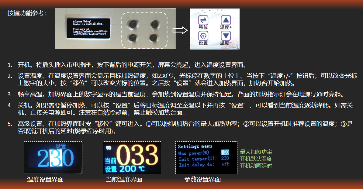
2. Function Description
: It can limit the maximum heating power of the heating platform, making it usable in dormitory environments with power restrictions (dangerous).
3. Circuit Principle Analysis
3.1. Schematic diagram
is attached. This document, source code, and demonstration video are also attached.
3.2. Optocoupler-SCR Circuit Design
▶ Comparison of Optocouplers and Relays Both
relays and optocouplers can achieve strong and weak current isolation and control large current with small current, so why use optocouplers/SCRs? If it's just about controlling on and off, a relay can be used. When I disassembled my Bear electric slow cooker, I saw that it used a Ronway relay. I think using a relay is perfectly fine and cheaper, but there are the following problems: ① The release and engagement of the relay spring requires a 10ms delay, so the PWM frequency cannot be too high; ② Frequent PWM switching will cause the internal contacts of the relay to wear out faster; ③ If the loop is closed or opened at the AC peak, it is easy to generate electric sparks, resulting in greater circuit noise. Therefore, considering factors such as lifespan, switching speed, and noise, an optocoupler-thyristor solution is used.
▶ The
working principle of the zero-crossing optocoupler + bidirectional thyristor circuit is as follows: When the PWM level is high, the transistor S8050 conducts, causing the optocoupler to conduct. Compared to ordinary optocouplers, the conduction or cutoff state of the zero-crossing optocoupler CT3063 only changes when the AC voltage crosses zero, avoiding electrical sparks. After the zero-crossing optocoupler conducts again at the next zero-crossing point, the 220V AC initially flows from the live wire through R3, the gate (G) pin of the thyristor Q1, to the T1 pin, then through the heating element from PTC_L to PTC_N, and finally into the neutral wire. When the voltage across R7 exceeds the gate trigger voltage of the thyristor (V_GT>0.8V, or trigger current I_GT>10mA), the thyristor BT138 conducts (equivalent to a short circuit between T1 and T2), and the AC current mainly flows from the thyristor to the heating element, causing the voltage across R3 and R7 to drop to 0. When the PWM level is low, the optocoupler disconnects at the next zero-crossing, and the conducting SCR also disconnects, interrupting the current flowing to the heating element.

When selecting the optocoupler, the peak breakdown voltage (V_DRM), also known as the off-state output terminal voltage, needs to be considered. The CT3063 has a breakdown voltage of 600V, which is greater than the mains voltage amplitude of 1.414 * 220V = 310V, meeting the requirements.
The selection of the bidirectional SCR also needs to consider the repetitive peak blocking voltage V_DRM and the maximum on-state current I_T (RMS). The BT138-800E has a blocking voltage of 800V and a maximum current of 12A, meeting the power requirements of the heating platform.
▶ R5 Calculation:
The function of R5 is to limit the current of the optocoupler LED. If we ignore the voltage drop V_CE of the S8050 transistor, then R5 = (VCC - V_F) / I_FT. Its value needs to consider the following parameters:
Input Trigger Current I_FT: The optocoupler can only be stably triggered if the current is greater than this value. Although the STM32 pins can withstand a direct output current of 5mA, it is still recommended to use a transistor as an adapter to reduce the heat generated by the STM32.
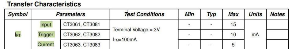
Maximum Input Current I_F: This parameter can be found in Absolute Maximum Rating. The input current must not exceed this value.

Forward Voltage Drop V_F: There will be a certain voltage drop across the LED inside the optocoupler.

Based on the above values, the range of values for the current-limiting resistor R5 can be calculated.
▶ R3 Calculation

R3 also functions as a current-limiting resistor, and its value is determined by the peak repetitive surge current I_TSM (Peak Repetitive Surge Current). R3 = Peak AC mains voltage / I_TSM = 310V / 1A = 310Ω. However, since this value is usually not included in the resistor packs we buy, we choose the closest 300Ω or 360Ω.

▶ R7 Value:
R7 is a resistor to prevent the SCR from being falsely triggered and can be disconnected. If R7 is disconnected, when the SCR is turned off, because the load current lags the voltage, it may transmit a small step voltage to pin G, causing the SCR to be falsely triggered. As a result, the load after the SCR will continue to work and cannot be stopped. Adding R7 is equivalent to pulling pin G to pin T1, making the SCR less sensitive. The value of R7 is quite flexible; online solutions show values up to 1kΩ. To save on component purchases, the same value as R3 can be used.
The resistance values of R3 and R7 affect the electromagnetic interference (EMI) of the system. When the voltage drop across R3 is large, a larger voltage is required between pins T1 and T2 before the SCR conducts, resulting in greater circuit noise.
During normal operation, the average power passing through R3 and R7 is relatively small, but the resistors need to withstand high voltage. Therefore, it is recommended to choose through-hole resistors or connect multiple surface-mount resistors in series. In my actual tests, I used a 2512 package. After prolonged operation, R3 generated significant heat, while R7 and the SCR did not.
Note: I am not entirely clear on the calculations for R3, R7, etc., and I do not have an oscilloscope on hand. It would be best to measure the signal after the SCR when possible.
▶ RC Circuit
If the controlled voltage changes too quickly, exceeding the critical rate of rise of off-state voltage, the thyristor will also be falsely triggered. The parallel RC branch can act as a buffer. Since the PTC heating plate is almost a resistive load, an RC absorption circuit is not required. The complex impedance of the RC series is Z = Rj*[1/(2πfC)]. Since the capacitance is very small, the AC current will not short-circuit through the capacitor.
▶ References:
[1] Cao Xiaowei. MOC3061 series photoelectric bidirectional thyristor driver[J]. Foreign Electronic Components, 1996,(12):2-4.
[2] Parameter list for SCRs, Triacs, AC Switches, and Diacs
3.3. Temperature control design
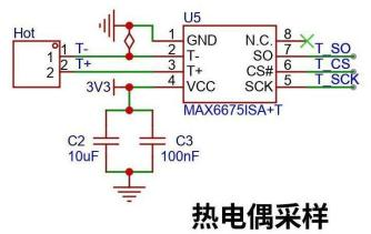
▶ K-type thermocouple characteristics and temperature acquisition
In a K-type thermocouple, the positive electrode is usually nickel-chromium alloy and the negative electrode is usually nickel-silicon alloy. When there is a temperature difference at the junction of the two metals, a thermoelectric potential will be generated. Because the potential value is very small, the MAX6675 is used to convert the voltage signal of temperature into a 12-bit digital value with an accuracy of 0.25℃.
The MAX6675 has built-in cold junction compensation, so the chip should not be exposed to heat for too long during soldering. A few days after soldering, I measured the room temperature and it was 40℃. After half a month, the temperature returned to normal, which was quite amazing. Since the author did not have a thermometer for measurement and calibration, the temperature results are based on the readings from the MAX6675.
▶ PID Temperature Control Parameter Adjustment Suggestions:
Due to the approximately 5-second delay from heating to heat transfer to the heating element surface, this is considered a high-delay system. Therefore, initially set p, i, and d to 0. First, adjust p to reach the target temperature quickly without strong oscillations, then increase the d value to reduce oscillations. The i value does not need to be adjusted; an excessively high i value will exacerbate temperature fluctuations.
▶ Heating Model and Improvement Directions:
This project currently uses a classic PID algorithm, with temperature fluctuations within ±5℃. To improve temperature control accuracy, further improvements can be made by using a fuzzy PID control algorithm.
The physical model of this heating platform basically conforms to a first-order inertial object with pure delay. The temperature G as a function of time s satisfies the formula:

where K is the system gain, T is the inertial time constant, and τ is the pure time delay constant. By measuring the temperature change curve of the heating platform over time, these three parameters can be determined. Then, a fuzzy PID control algorithm is used to control the temperature in segments.

3.4. The power supply

uses an HLK-PM03 module to convert 220V to 3.3V to power the microcontroller. Note that a fuse should be installed, R1 is a varistor for lightning protection, and R2 is for output short circuit protection. Since there are no high requirements for voltage stability, safety capacitors and common-mode inductors are not added.
4. Code Architecture and Problem Records
4.1. Overall Code Idea
Since the basic functions required by the heating platform are too simple, it can be directly programmed in bare metal. No FreeRTOS or task scheduling library is needed; interrupts are sufficient. Timer TIM1 generates an interrupt every 1 second to measure the temperature. After temperature measurement, the new temperature value is displayed on the LCD screen, and a PID temperature control is calculated. Then, timer TIM2 is set to output a new duty cycle. Finally, the MCU returns to low power. When a button is pressed, an interrupt is generated, causing the MCU to exit low power and update the LCD screen interface. Finally, the MCU returns to low power.

To ensure accurate temperature measurement, the interrupt for timed temperature measurement has the highest priority, and the communication process with the MAX6675 is completed in the interrupt function. Since the screen update takes a long time, only the "LCD display needs to be updated" interrupt flag is marked in the interrupt function. The specific page to which the screen switches is executed outside the interrupt function. This also avoids the screen from updating another page while updating another page, which would cause the display to freeze.
A capacitor is connected in parallel with the button for debouncing. At the same time, a non-blocking cooling time is set in the software to avoid a large discrepancy between the sensitive "temperature +/-" button and the user's expectations.
4.2. Project File Description
This is the project folder. Only the code in the four folders in the box in the image below is actually used. The others are files generated by IAR and VSCode. If you use IAR, you can open the project directly; if you want to port it to Keil, you need to create a project from the code in the four folders and replace the core_cm3.c and .h files with the ones supported by the Keil environment.

4.3. Using the STM32's internal clock
Since no crystal oscillator is connected, the STM32 automatically uses the internal high-speed clock HSI, with a frequency of 8MHz. In the project code, HSI is multiplied to 64MHz by a PLL as the system clock source.
4.4. Using the built-in Flash to retain settings
The data settings in the project code are written cyclically to sector 30 (the second to last sector) of the STM32C6T6's built-in flash, so the content is not lost after power-off. Cyclic writing reduces the number of erase cycles and extends the life of the flash. If you modify the code in this project, please be careful not to store the program in this sector.
5. Burning and Assembly
5.1. Burn
the IAR-compiled firmware "HeaterC6T6.hex" in the "./Debug/Exe/" path.
Disconnect the 220V AC power and connect the ST-Link's four wires: 3V3, GND, SWCLK, and SWDIO, then plug it into the computer. The problem might be due to an interrupt service routine being enabled in the code, causing the program to fail to burn the first time. To save materials, this heating platform doesn't have a reset button for the STM32 in the circuit, so the online method of "clicking to burn and then briefly pressing the reset button" won't work. The solution found is to burn the program or erase the flash memory after plugging the ST-Link into the computer, just before the program enters the interrupt (the first `delay()` line in `main` provides ample time).
If burning using IAR, the project's `Reset` method must be set to `Core` (default is `system(default)`). Otherwise, it will report the error "fatal error: initial reset failed, please check project settings".

If using the "STM32 ST-LINK Utility" software: after plugging the ST-Link into the computer, immediately click "Target - Erase Sectors..." to erase the program. If erasing fails, click "Target - Option Bytes..." to unlock the flash's readOnly setting. If it fails to unlock on the first try, try again, then erase. Afterward, the burning process should proceed without errors.
5.2. Component Costs:

Material costs are approximately 70 RMB, with additional costs expected. Soldering iron, drill, file, pliers, and other processing tools will cost approximately 100 RMB.
PTC heating elements, studs and nuts, power cords, and 220V to 3V3 modules constitute the main cost of the heating platform; these can be purchased on Taobao. Resistors and capacitors are more cost-effective to purchase from LCSC Mall.
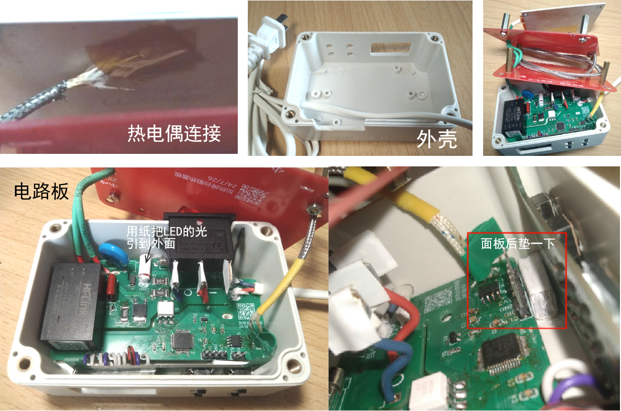
5.3. Problems Encountered During Assembly
: Thermocouple Fixing: I chose to directly attach the exposed thermocouple wires to the back of the heating platform using high-temperature tape, so the measured temperature is the lower surface. The excess thermocouple wire was coiled up and tucked into the space of the first cover plate. The thermocouple also transfers a significant amount of heat to the lower surface.
Pad Adjustment: The holes for the pads connecting the heating platform and power cord need to be enlarged!
Waterproof Box Slot Hole: A 60W impact drill with a 3-5mm drill bit was used to drill holes. A rough shape was first drilled, then cut with electronic pliers, and the slot was smoothed with a file.
Rocker Switch: The 3mm thickness of the waterproof box is a bit too much; the clips behind the rocker switch need to be shortened slightly. Some rocker switches have lights, requiring the neutral wire to be connected to the third pin of the switch to illuminate. In this design, only two pins are used, so the light on the switch does not illuminate.
LCD Screen: Some screens on Taobao are BGR; the code needs to be reversed to BGR to display RGB.
Display Panel Flying Wires: Soldering requires patience; solder the copper wires thoroughly before soldering them to the pads. Any loose wire will eventually cause problems.
Button Recessed into the Housing: Place a paper block behind the panel to prevent deformation and displacement.
Fasteners: Iron hexagonal studs can be used, although they have slightly lower thermal conductivity than copper. The studs, screws, and nuts are all M3.
Insulation: A layer of heat shrink tubing is used to cover the power cord of the heating plate, and a layer of high-temperature tape can be applied to the heating surface
. From a workload perspective: it's better to just buy an 80 RMB heating plate from Taobao, which is exactly the same as the one used in the lab.
If heated for 20 minutes, the temperature of the lower cover plate remains almost unchanged in the short term. If heated continuously for 3 hours, the temperature at the center of the lower cover plate can rise to about 60℃, feeling slightly hot to the touch; the upper cover plate is even hotter. Currently, the heating plate can operate at high temperatures for extended periods, but heat dissipation needs improvement.
6. Acknowledgements: Thank
you to JLCPCB for providing 80 RMB worth of components through their 2024 Spark Program! This allowed me to attempt building a complete project for the first time. There are many errors and irregularities in the project; please point them out.

[Easy to store and pack away]
Functionality verification video.mp4
Compiled firmware_241102.hex
Heating Table Instruction Manual 241102.pdf
Source code_241102.zip
PDF_Controllable Temperature Heating Stage Based on STM32F103C6T6 and Optocoupler SCR.zip
Altium-based temperature-controlled heating stage using STM32F103C6T6 and optocoupler SCR.zip
PADS_Controllable Temperature Heating Stage Based on STM32F103C6T6 and Optocoupler SCR.zip
BOM_Controllable Temperature Heating Stage Based on STM32F103C6T6 and Optocoupler SCR.xlsx
90770
8-bit fluorescent tube clock
8-bit fluorescent digital clock.
Dynamic refresh method, two-board design, fewer components.
I. IC Overview
1.1 Fluorescent Tube Driver IC -
HV5812 I saw the HV5812 chip in another post on CSDN: The Soviet IV-18 fluorescent digital tube clock development (ИВ-18)
This chip is not widely used, I think for the following two reasons:
it is hard to buy and too expensive (15 RMB per chip on Alibaba, excluding shipping).
For the solution in this article that only uses one HV5812, it can only be dynamically refreshed, so a higher gate voltage is needed.
The solution of ULN2803 Darlington tube + decoder is static refresh, which is brighter at the same gate voltage (dynamic refresh is basically unusable at this voltage).
The reasons for choosing HV5812 as the driver in this article are as follows:
saving PCB area, not needing to use 8 decoders and 8 driver ICs
to complete data transmission using SPI interface, occupying fewer MCU pins.
ULN2803 is an 8-bit Darlington tube, but YS27-3 is a 9-segment tube, so one segment cannot be displayed.
The HV5812 has 20 outputs. Half of the outputs can be used to control the fluorescent tube gate, and the other half can control the fluorescent tube segment code.
1.2 MCU__STM32F103CBT6
is mainly because it is in an LQFP48 package. If there were fewer pins, it would be a QFN package, which is difficult to solder.
When the questioner was doing this, he was not very familiar with ST's microcontrollers, but since they are mainstream, he should gradually learn them to facilitate porting.
1.3 WIFI__ESP-01F
is a small-sized WiFi module from Anxinke, with SPI and serial ports. The WiFi chip is Espressif ESP8285.
This development used the built-in AT firmware. Actually, it is also fine to use this directly as the main controller.
1.4 Clock IC__DS3231
is a very old clock chip. It is used for timing, power-off saving, and generating a 1Hz interrupt.
II. Hardware Circuit
2.1 HV5812
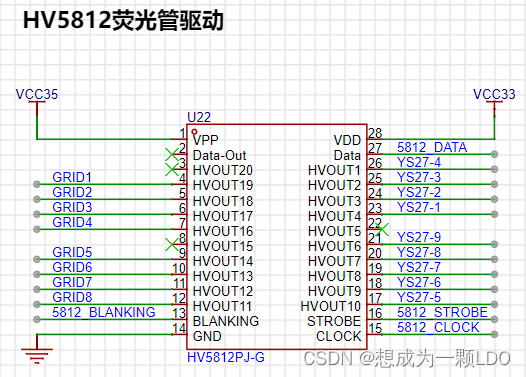
|Network Name| Description|
|--|--|
|VCC35 | VFD Drive Voltage|
| VCC33 | 3.3V |
| GRID1—GRID8| Gates of fluorescent tubes 1-8|
| YS27-1—YS27-9| Segment codes of fluorescent tubes, all fluorescent tube segment codes are cascaded|
| 5812_BLANKING| SPI chip select line, connected to the CS pin of the SPI host|
| 5812_DATA| SPI data line, connected to the MOSI pin of the SPI host|
| 5812_STROBE| Latch, high level latches the current display status|
| 5812_CLK| SPI clock line, connected to the CLK pin of the SPI host|
2.2 STM32F103C8T6

Minimum System:
| Network Name| Description|
|--|--|
|VCC33| 3.3V power supply|
|NRST| Reset|
|SWCLK| SWD clock line|
|SWDIO| SWD data line|
|BOOT0| Boot position selection|
|BOOT1| Boot position selection|
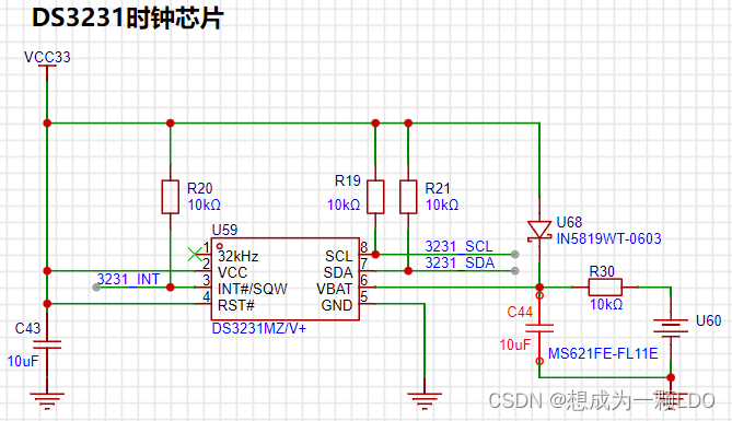
DS3231:
| Network Name| Description|
|--|--|
| 3231_SCL| DS3231 IIC Clock Line|
| 3231_SDA| DS3231 IIC Data Line|
| 3231_INT| DS3231 Interrupt Line| The
DS3231 uses the IIC bus. SCL and SDA require pull-up resistors, as shown in the DS3231 schematic below.
In addition, an interrupt line is connected, which can configure the DS3231 register to output a 1Hz or 32.768kHz interrupt signal. This is mainly to save MCU computing power by reading via IIC after the clock update. Because we are using the persistence of vision effect to dynamically refresh the fluorescent tube, performing time-consuming operations will reduce the refresh rate and significantly affect the viewing experience. Therefore, it is crucial to avoid continuous time-consuming operations when writing the program.
HV5812:
|Network Name| Description|
|--|--|
| 5812_STROBE| HV5812 latch, high level latches the current display status|
| 5812_CLK| HV5812 clock line, connected to the CLK pin of the SPI host|
| 5812_DATA| HV5812 data line, connected to the MOSI pin of the SPI host|
| 5812_BLANKING| HV5812 chip select line, connected to the CS pin of the SPI host|
ESP-01F:
|Network Name| Description|
|--|--|
| ESP_RX| ESP-01F serial port receive pin, connected to the TX pin of the MCU| | ESP_TX|
ESP-01F serial port transmit pin, connected to the RX pin of the MCU|
| ESP_SPI_MOSI| ESP-01F SPI MOSI pin, connected to the MISO pin of the MCU SPI|
| ESP_SPI_MISO| ESP-01F SPI MISO pin, connect to MCU SPI MOSI pin |
| ESP_SPI_CLK | ESP-01F SPI CLK pin, connect to MCU SPI CLK pin |
| ESP_SPI_CS | ESP-01F SPI CS pin, connect to MCU SPI CS pin |
Other:
| Network Name | Description |
|--|--|
| BUZZER | Buzzer, connect to a timer that can output PWM |
| LED1 | LED2 |
| LED2 | LED1 |
| KEY1 | Button1 |
| KEY2 | Button2 |
2.3 ESP-01F
can be connected according to the datasheet. Because it is an RF module, pay attention to the layout considerations in the manual.
A TX/RX pin is reserved for debugging.
When the MCU configures the corresponding pin of the UART for digital function, the external UART (serial-to-USB debugger) will be unusable. Simply disable the digital function when debugging with a PC.

2.4 The DS3231
doesn't require much explanation.
The spare battery on the right uses a charging circuit, which I found on CSDN.
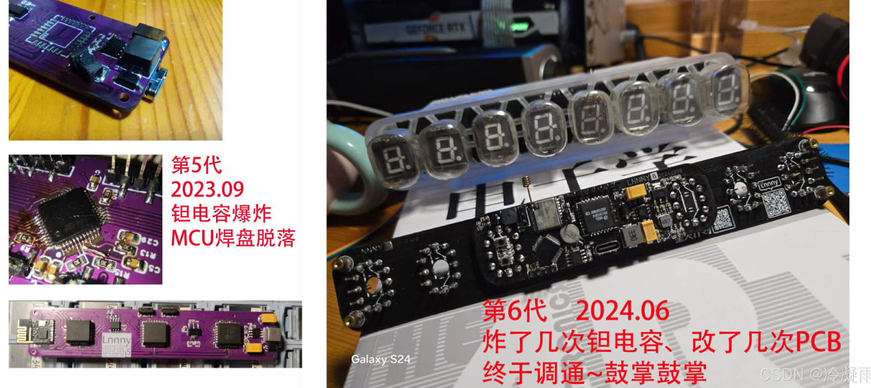
2.5 The XL6007E1 boost circuit
provides the driving voltage for the fluorescent tube. Here, it boosts 5V to 35V.
I didn't actually use 35V (because the tantalum capacitors exploded several times...), but you can adjust it according to your needs.
The YS27-3 manual states that the gate voltage is 12V, and the duty cycle operating voltage is higher (I remember the operating voltage at 50% PWM is 50V).
Since we are using dynamic refresh, a higher voltage is fine, depending on your brightness requirements.
It's worth noting that to save space, the boost circuit uses tantalum capacitors, but their voltage rating is low; the output voltage cannot exceed the rated voltage!
A larger C51 capacitor results in lower power ripple, but also a lower voltage rating! Therefore, it's not easy to find high-voltage tantalum capacitors.
Currently, I'm using a 28V operating voltage and a 47uF 35V tantalum capacitor. I haven't tested the power supply ripple yet, but it works.
(The questioner knows very little about BOOST circuits; this circuit is for reference only. Please be careful during debugging to prevent capacitor explosion.)

2.6 1.2V step-down circuit:
A step-down circuit I found on CSDN. It works in practice.

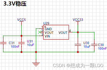
2.7 3.3V voltage regulator circuit.
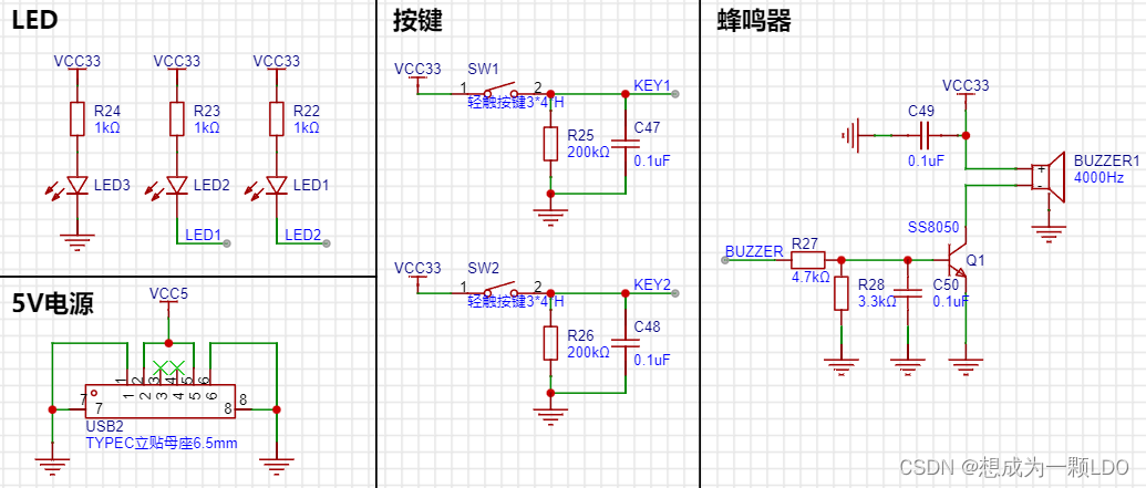
2.8 Buzzer, buttons, and LEDs.
III. Conclusion
: I started working on the fluorescent tube clock during my master's program while staying home during the pandemic. Because I'm a mechanical engineering major, I didn't know anything about circuits at the time.
Looking back, I had a bad habit: I didn't settle down and learn before starting.
Therefore, I always encountered small problems that I couldn't solve, and I would think of giving up;
or I would be a perfectionist and want to redo everything if there was even a small problem.
But even if I didn't do it well, I would always remember to continue after a while.
This is why it took me so long to do it on and off.
Always trying to do it perfectly in one step only takes you further and further away from success.
Below are some previous versions.
Although progress is slow, the most interesting part is definitely the process itself!
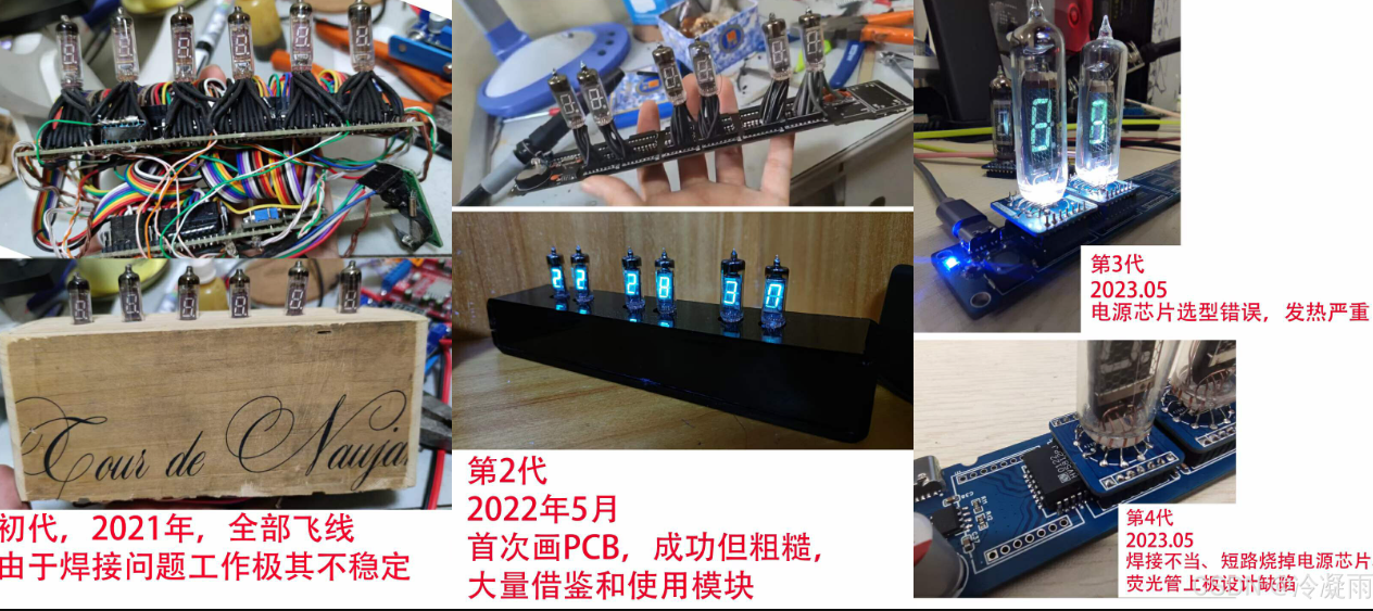
I hope those who are passionate about it can persevere and find joy in every step forward!
Keep up the good work!
YS27_3_CUBE_MX.zip
Demo video.mp4
PDF_Fluorescent Clock.zip
Altium_fluorescent clock.zip
PADS_Fluorescent Clock.zip
BOM_Fluorescent Clock.xlsx
90771
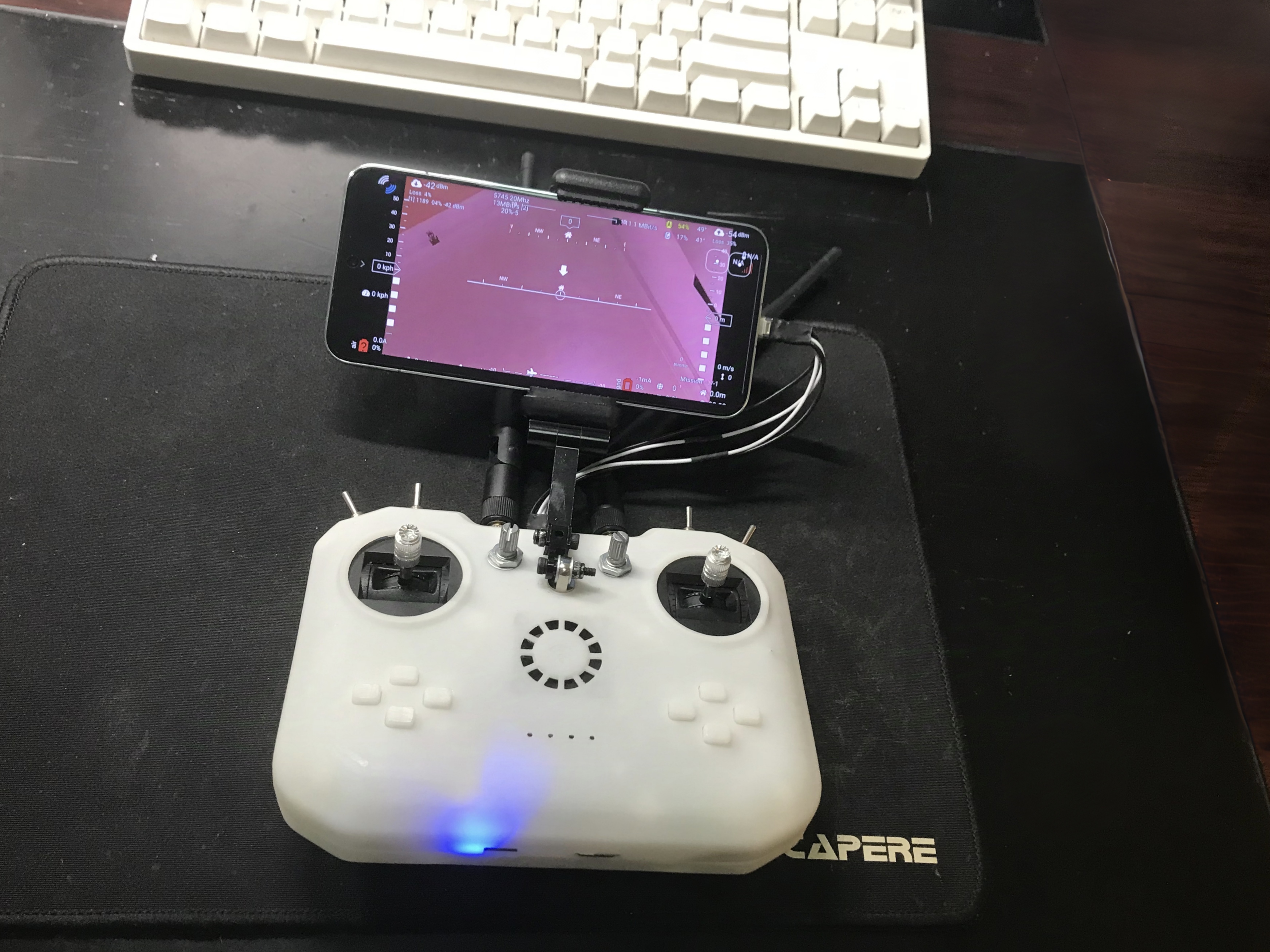
High-definition image transmission remote control
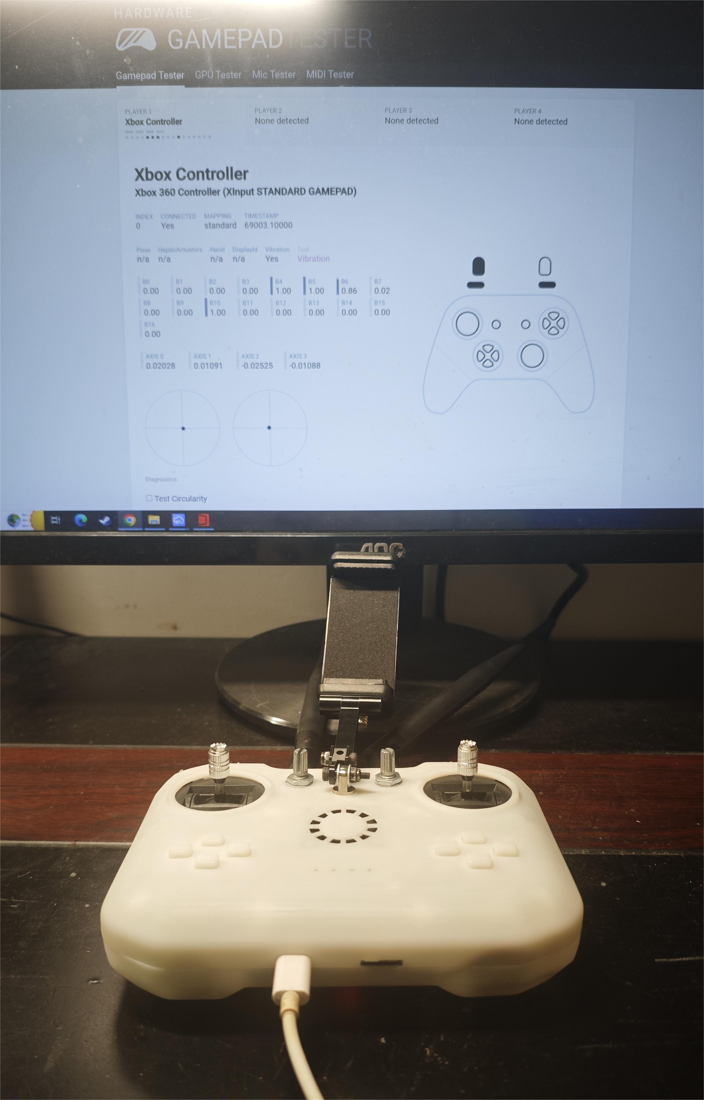
This project, based on OpenHD, aims to design a remote control device with high-definition digital image transmission capabilities, combining image transmission and remote control functions.
1. Project Description
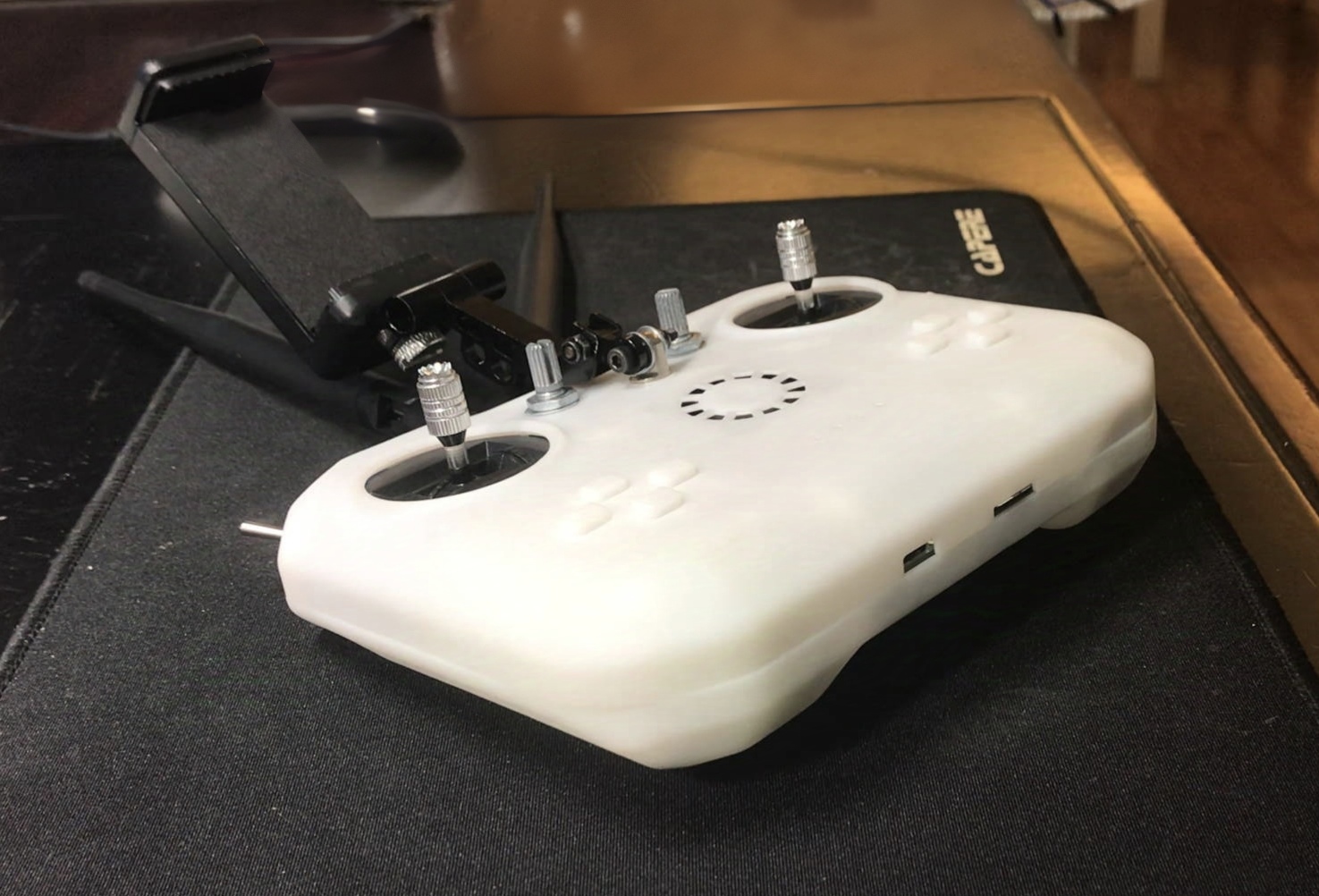
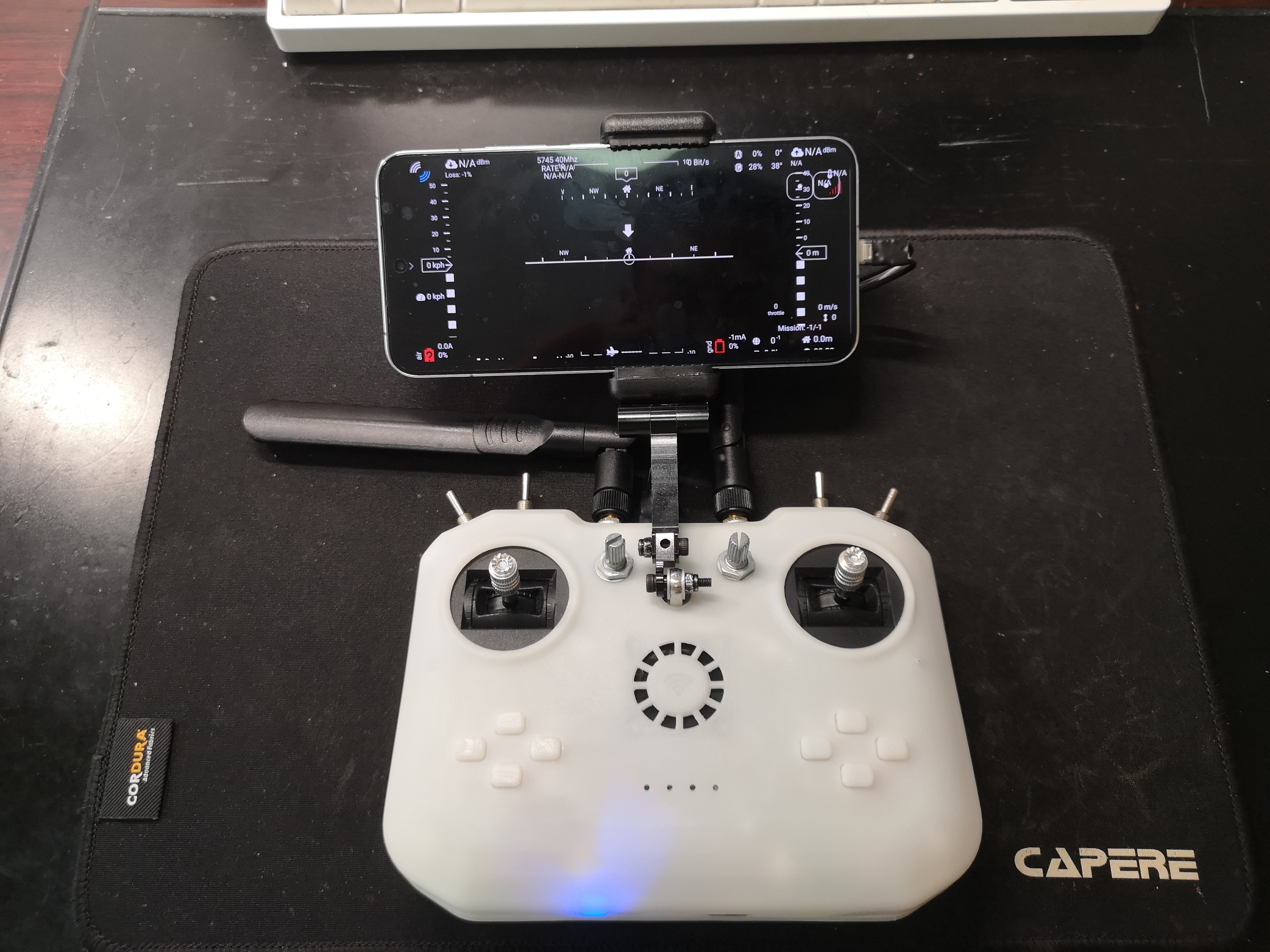
This project designs a remote controller with digital image transmission capabilities based on a Raspberry Pi. It only requires a single aerial unit and a camera to simultaneously transmit image data and receive remote control data, similar to DJI's remote controllers. This project is based on OpenHD, supports 16-channel data transmission, outputs an SBUS signal from the aerial unit, and displays the transmitted image on a mobile phone or HDMI screen on the ground unit. It also includes built-in charging management functions.
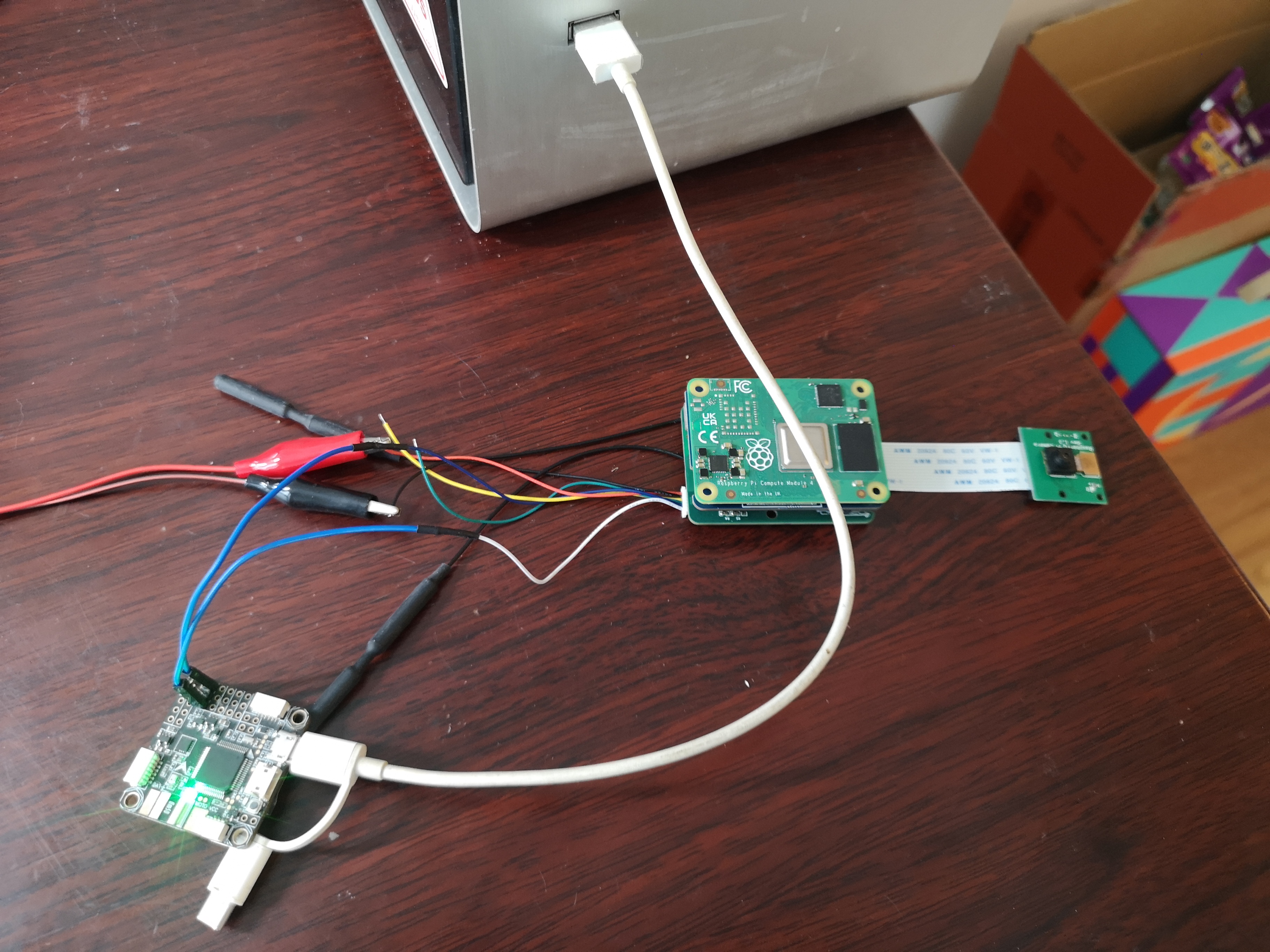
This project only includes the development of the ground unit remote controller; the aerial unit PCB in the project is only used for functional verification.
2. Open Source License CC BY-NC-SA 4.0 : Creative Commons License
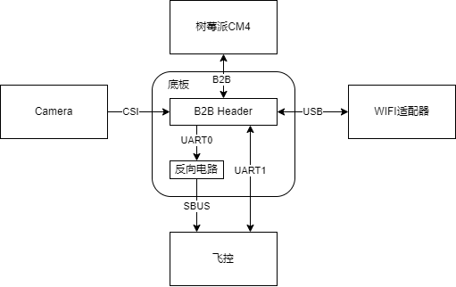
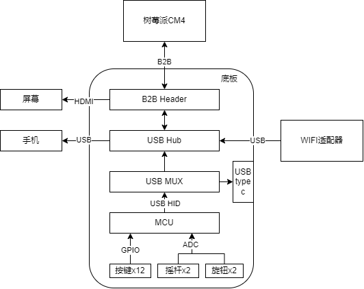
- Attribution-NonCommercial-ShareAlike CC: Abbreviation for Creative Commons license BY: Attribution, you must give appropriate credit, provide a link to this license, and indicate whether modifications were made (to the original work). SA: ShareAlike, if you remix, transform, or build upon this work, you must share your contributions under the same license as the original. NC: NonCommercial, you may not use this work for commercial purposes. 3. Project-Related Functions 3.1 Image Transmission: The aerial camera captures real-time images and transmits them to the ground-based remote controller via Wi-Fi. The remote controller supports USB connection to a mobile phone or HDMI connection to a screen for image display. The current camera transmission image specification is 720P@60. 3.2 Remote Control Data Transmission: The remote controller supports 6 analog channels and 10 switch channels. The aerial end supports receiving remote controller data and outputting it via the SBUS protocol. Here, the aerial end is connected to the SBUS interface of the flight controller, and then the remote control signal received by the flight controller is viewed on the computer using QGroundControl. 3.3 Controller Simulation: The remote controller supports USB connection to a computer and simulates an XBOX controller. 3.4 Charging Management: The remote controller has a built-in lithium battery charging management function, charging via connection to a computer or USB charger. 3.5 Other Features : The remote controller includes a mobile phone holder and a heat sink. 4. Project Attributes: This project is being publicly disclosed for the first time and is an original project by the author. This project has not won any awards in other competitions. 5. Project Progress: September 21, 2024: HDMI screen display, image transmission, mobile phone image display, computer and ground joystick recognition, sky-end receiving remote control data , SBUS data output, flight controller recognizing remote control data, power switch control , lithium battery charging, remote control data flow switching, 3D shell (first version) . 6. Design Principles : OpenHD currently offers the best support for Raspberry Pi. This project uses a Raspberry Pi CM4 for development. The following is a description of the sky and ground ends . 6.1 Sky End: The sky end completes camera data acquisition, WIFI data transmission, RC data reception, SBUS data encapsulation, and serial port data transmission. The hardware block diagram is shown below. 6.2 Ground End: The ground end completes image transmission signal reception, image decoding, joystick data acquisition, and WIFI data transmission. Because the OpenHD firmware only supports USB gamepads as input, the joystick and button data needs to be collected and transmitted to the Raspberry Pi via USB HID. An STM32 chip is used to complete data acquisition and gamepad simulation functions. The advantage of this is that the USB data can be output to the computer via the Type-C interface for data reception testing and emulator connection. The hardware block diagram is shown below. 6.2.1 The power supply design of this system requires a 5V power supply for the Raspberry Pi CM4, a 5V and a 3.3V power supply for the WiFi module, and a 3.3V power supply for the MCU. Additionally, the charging of the built-in lithium battery and the direction of USB HID data transmission when the USB is plugged in must be considered. The requirements are quite complex. To simplify the design, the automatic switching function between lithium battery charging and battery power is not implemented. Instead, a switch is used to switch between charging and power supply modes. The relationship between the switch and the USB is as follows: Switch on , Switch off, USB plugged in , image transmission runs, remote control data is sent to the Raspberry Pi; battery not charging , image transmission is off, remote control data is sent to the USB interface; battery charging, USB unplugged, image transmission runs, remote control data is sent to the Raspberry Pi; battery not charging , image transmission is off; remote control off, battery not charging. 6.2.2 Shell Design Reference Project: https://oshwhub.com/bukaiyuan/ESP32-hang-mu-yao-kong-qi 6.2.3 Interface Diagram 7 Software Description 7.1 Since OpenHD 's RC data is transmitted via serial port through MAVLINK, a flight controller supporting MAVLINK is required to receive the RC data. Therefore, for compatibility, a separate serial port is used to transmit RC data via the SBUS protocol. This requires modification of the OpenHD source code, which has been uploaded to my GitHub OpenHD repository: https://github.com/colourfate/OpenHD/tree/suppport_sbus 7.2 Ground Terminal 7.2.1 The OpenHD ground terminal does not require customization of OpenHD; the official OpenHD image can be directly flashed. 7.2.2 STM32 Firmware The ground terminal uses an STM32 chip to complete the joystick data acquisition and XBOX controller simulation functions. The following open-source project STM32 firmware is used directly: https://github.com/nesvera/STM32-X360-xinput/tree/master 7.3 Software Deployment 7.3.1 Flashing the OpenHD Image Download: Insert OpenHD ImageWriter into the TF card for flashing. Select Raspberry Pi evo-2.6.0 version. 7.3.2 Replace the OpenHD program in the Sky terminal by downloading and installing the ext4 file system driver. Insert the TF card, download the OpenHD program from the attachment, and replace the one in rootfs (it's best to back up the original one first). The path is /usr/local/bin. 7.3.3 Remote control firmware flashing for STM32.


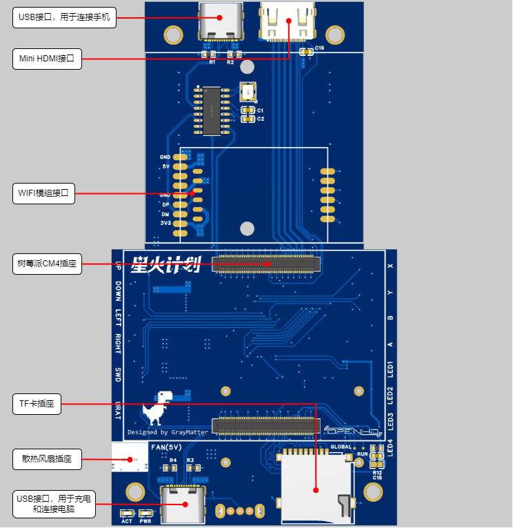


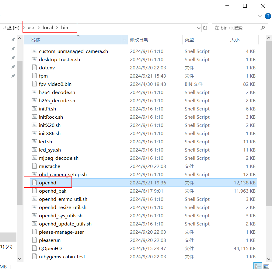
Download the STM32 firmware from the attachment and flash it via the onboard SWD interface. The SWD interface is on the back; refer to the interface diagram in 6.2.3. The pinout from top to bottom is VCC | CLK | DIO | GND
. 7.3.4 Install the QOpenHD APP on your phone.
Download QOpenHD .
8 Resource Summary
8.1 Material Recommendations
8.1.1 Ground Unit
Model
Quantity
Remarks
Core Board
Raspberry Pi CM4
1
CM4001000, without WIFI/EMMC, 1GB RAM
WIFI Module
RTL8812AU
1
Supports three modules:
1. A salvaged module, transmit power 150mW, requires flying wire soldering
2. Smart gateway hardware, transmit power 500mW
3. Bilian Electronics, transmit power 50mW
Charging Management Module
2S Charger
1
2S lithium battery charging module, refer to the link
Cooling Fan
-
1
Length 3CM/Width 3CM/Thickness 0.7CM, refer to the link
Joystick
-
2
small universal (centering) 5k with bearing, reference link; 2 5k 3-pin
rotary potentiometer
RK097NS , reference link; 4 3-pin 2-position toggle switch MTS-102 , reference link; 8 mute button , reference link ; 2 18650 lithium battery ( flat head recommended, with protection board) ; 1 USB Type-C USB 2.0 connector for making a double-ended USB cable to connect to a mobile phone (cannot use commercially available double-ended Type-C USB cables directly), reference link; this data cable looks okay , but hasn't been tested ; 2 5.8G WIFI antennas, reference link ; 1 universal phone screen bracket , reference link ; 1 M4 lifting screw (7mm long) for fixing the phone bracket , reference link; several M3/M2 screws for connecting joysticks, buttons, heat sinks, and countersunk nuts (M4 ), and several self-tightening nuts. 8.1.2 The overhead end has only been verified; the following materials are for reference only: Model, Quantity, Remarks; Core Board Raspberry Pi CM4, 1 CM4001000, without WIFI/EMMC, 1G memory WIFI module RTL8812AU 1 supports three modules: 1. A disassembled module, 150mW transmission power, requires flying wire soldering 2. Smart gateway hardware, 500mW transmission power 3. Bilian Electronics, 50mW transmission power Camera Raspberry Pi 1st generation 1 Reference link FFC flexible flat cable - 1 connects to the camera, 1mm pitch, 15P, same direction baseboard Microsnow Electronics 1 Raspberry Pi CM4 core board USB2.0/CSI interface expansion board Type A, reference link 8.2 Software Sky terminal OpenHD: Attachment 1 Remote control STM32 firmware: Attachment 2 8.3 Shell The first version has many problems, will be uploaded after improvement 9 Physical demonstration Bilibili video demonstration: https://www.bilibili.com/video/BV1Ju19YiEGk/?spm_id_from=333.999.0.0 10 Design considerations 10.1 The OpenHD official website describes the remote controller as follows: It's important to be aware that WiFi may not be ideal for transmitting many small RC packets. For the best experience, it's recommended to use a standard RC link operating on a different frequency than your OpenHD WiFi broadcast link. For example, you can use 2.4GHz ELRS for RC control and 5.8GHz for WiFi broadcast. In other words, WiFi is not an ideal communication link for transmitting small data packets like RC signals. For the best experience, it is recommended to use a standard RC remote controller on a different frequency band than WiFi. Therefore, this remote controller cannot replace a professional model aircraft remote controller. 10.2 Regarding the Sky Terminal : In this project, only the basic functions of the sky terminal have been verified, relying on a MicroSnow base plate. Considering the overall workload of the project, the sky terminal will likely be a separate project later. 10.3 Regarding Welding

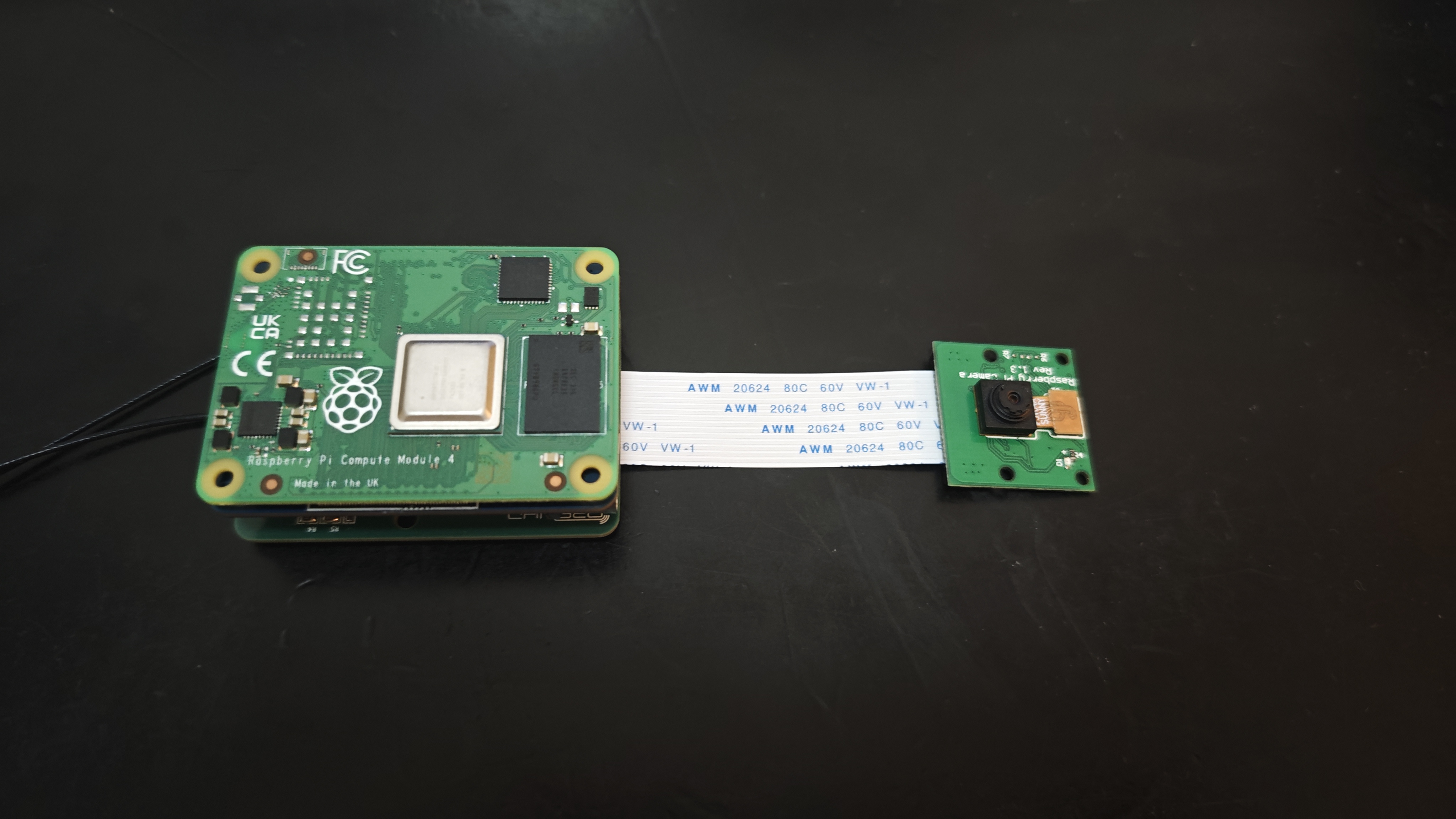
The Raspberry Pi CM4's two 100-pin connectors have a pin pitch of 0.4mm, and the module requires sufficient strength to insert and remove, making manual soldering very difficult. The recommended approach is to first tin all the pads, then align the connectors and place them on the connectors. Use a heated soldering iron for the first soldering attempt. Once the connectors are stable, use a very fine-tipped soldering iron to touch up the solder on each pin.
Also, when inserting or removing the connectors, apply parallel and even pressure; do not attempt to pull them out from one side.
openhd
stm32_xinput.hex
PDF_High-definition image transmission remote control.zip
Altium_HD Image Transmission Remote Control.zip
PADS_HD Image Transmission Remote Control.zip
BOM_High-definition image transmission remote control.xlsx
90772
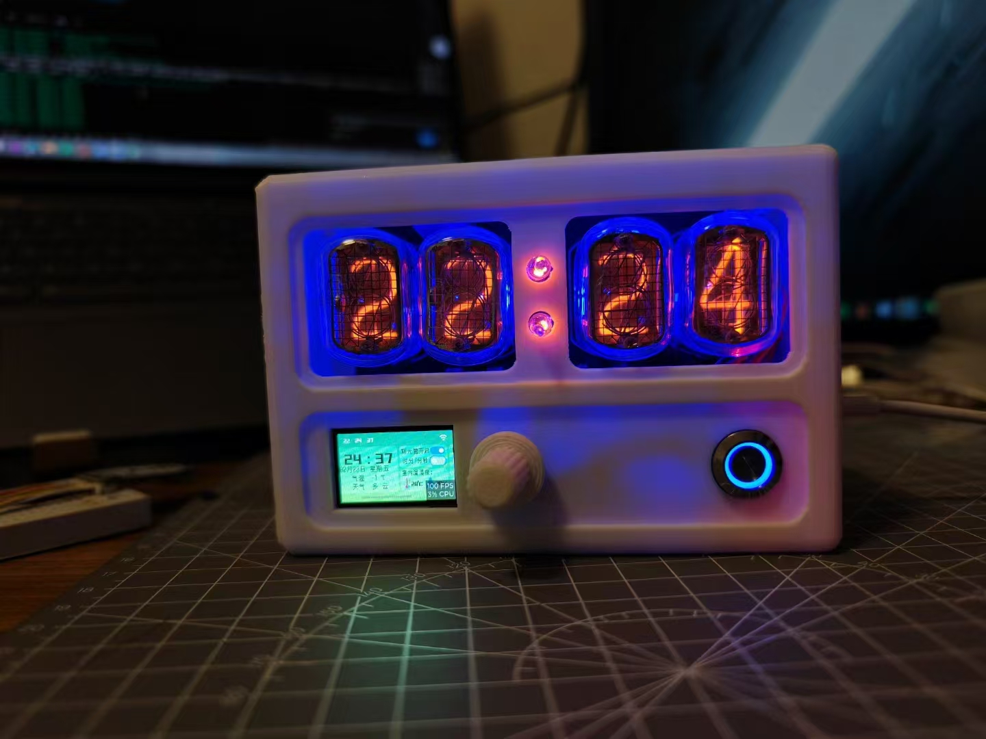
A glow tube clock that can be interacted with via a UI
A glow tube clock with a user interface (UI). The UI is designed using the LVGL graphics library, with an encoder as the input device. The UI can display information such as time, weather, and indoor temperature and humidity in modules. Users can control the glow tube and ambient lighting through the UI. It can also connect to the internet to calibrate the time and obtain weather information.
Video Link:
Bilibili Video -- Function Demonstration and Introduction
Project Overview
This project is a Nitrogen Glow Tube clock based on the ESP32S3. Users can configure the ESP32S3 via their mobile phones. After connecting to Wi-Fi, it will automatically calibrate the time and obtain weather information for the target city. Users can interact with the UI through the encoder. The UI can display the time, date, weather, temperature, indoor temperature and humidity, Nitrogen Glow Tube on/off status, Nitrogen Glow Tube display mode, ambient light mode, and custom ambient light color data on the corresponding modules. Users can control the Nitrogen Glow Tube and ambient light through the UI.
Project Function
Power-on: The project uses a Type-C interface for power supply. After plugging in the data cable, press the self-locking button to power on. After powering on, the UI displays "WiFi connecting..." in a black transparent prompt box. The prompt box hides after about 10 seconds of WiFi not being connected.
WiFi Configuration: Ensure the mobile phone is connected to 2.4G WiFi, open the ESPTouch app, enter the WiFi password, and connect. After a successful WiFi connection, a prompt box appears, adding "WiFi connection successful" and "Obtaining NTP server time...". If the acquisition is successful, "Acquisition successful" is displayed; otherwise, "Acquisition failed" is displayed. After a successful WiFi connection, the system automatically retrieves the weather and temperature of the target city (using the Xinzhi Weather service) and displays it in the corresponding module.
UI Interaction: Users interact with the UI using the encoder. Rotating the encoder moves the focus to different modules, and the panel scroll bar also moves, displaying the focused module on the screen. When focused on a module, pressing the encoder moves the focus to a control within that module. When focused on the module again, pressing the encoder exits the focus process, moving to the next module. When focused on a switch, pressing the encoder toggles the switch's state. When focused on a button, pressing the encoder presses the button. When focused on a slider, pressing the slider selects it; rotating the encoder left or right changes the slider's value; pressing the encoder again exits the focus process. Each encoder operation triggers a buzzer.
Glow Tube: The "Glow Tube On" switch in the UI is enabled, displaying the time in hours and minutes by default. The "Hours/Minutes/Seconds" switch in the UI also enables the glow tube to display the time in minutes and seconds. After the glow tubes are lit, every 5 seconds, all the numbers on each tube light up sequentially to prevent cathode poisoning.
Ambient Lighting: When the "Auto" switch is turned on in the UI, the ambient light will automatically change color and brightness in a gradient manner. When the "Auto" switch is off, users can select different numbered RGB lights and change the values of the R, G, and B sliders to customize their color and brightness.
Project Parameters:
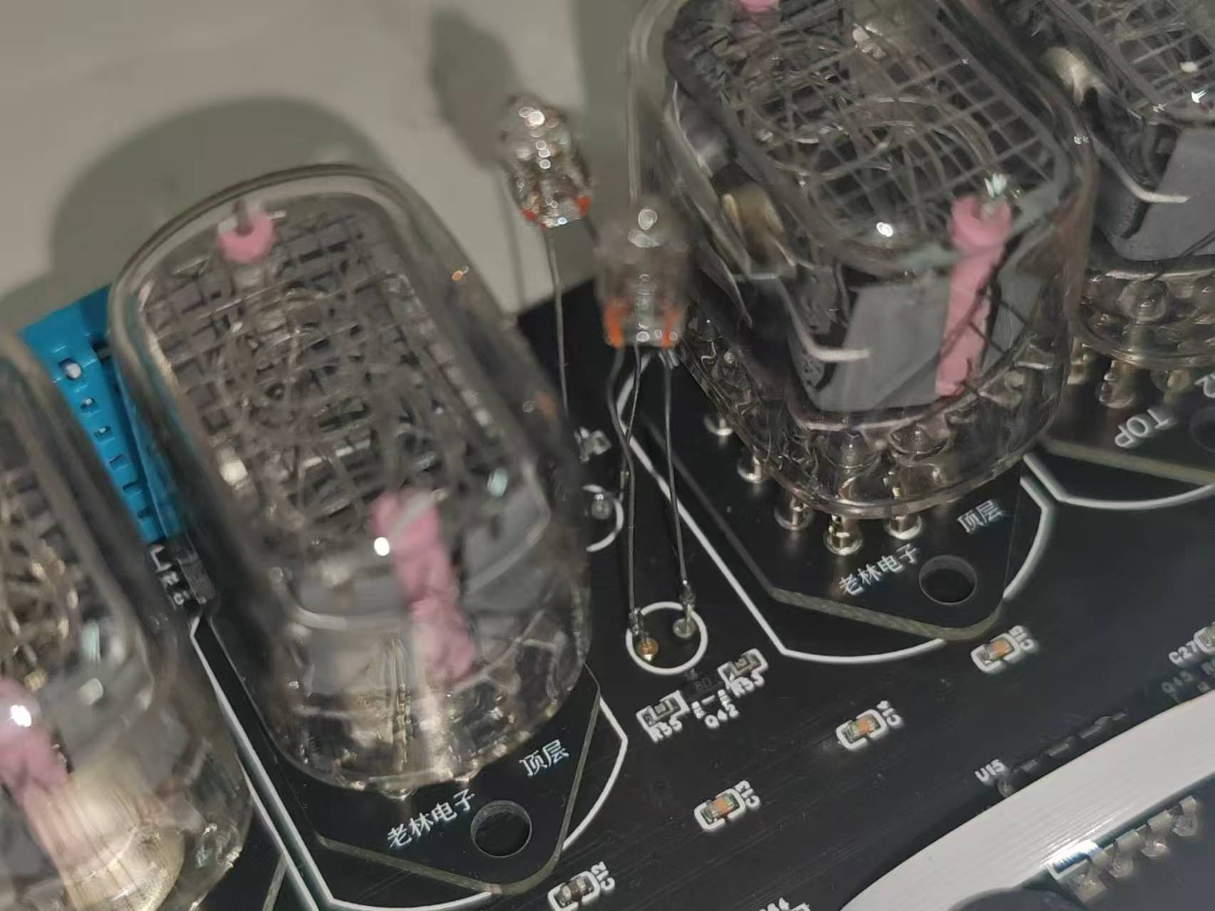
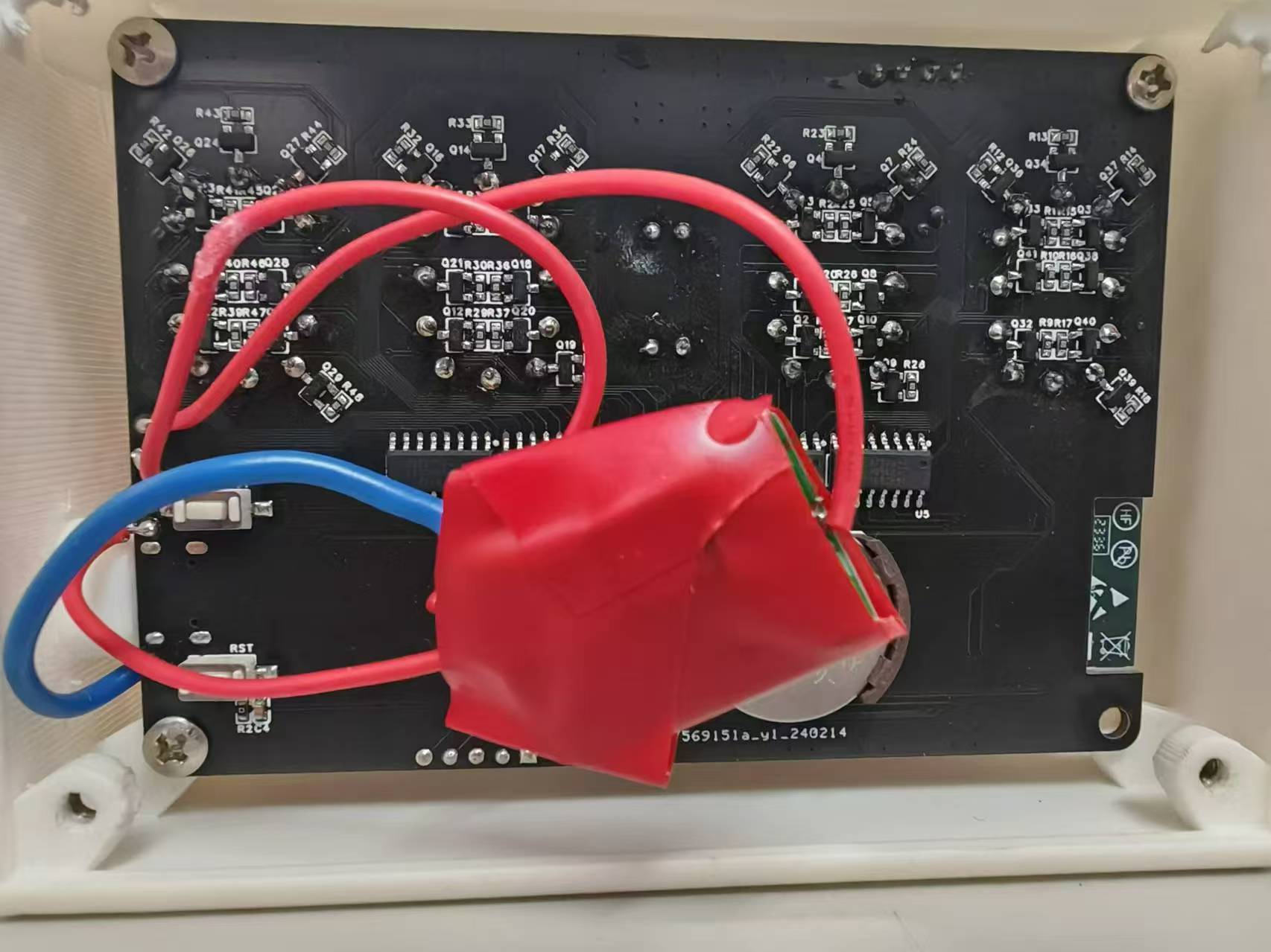
The project uses a DS1302 RTC chip and a button battery as backup power, allowing for timing even in the event of a power outage. The author used a DIP packaged chip in this project because it was readily available, and surface-mount packaging was not used to avoid waste. Surface-mount packaging can be modified accordingly if desired.
The project uses a DHT11 temperature and humidity sensor, which has a wide temperature measurement range and can meet general needs. If the device is powered on for an extended period, the temperature and humidity values will be affected by heat; this phenomenon will be more noticeable when the glow tube is turned on.
The project uses a 1.14-inch plug-in LCD screen with an ST7789V driver chip, a resolution of 135*240, and a GUI for user interaction.
This project uses WS2812 5050 RGB LEDs to implement ambient lighting. Users set the desired color via a UI, and the main controller transmits the corresponding data via a single bus to achieve changes in LED color and brightness.
The encoder module used is KY-040 FOR. The
push-button switches are 12mm blue ring-shaped metal push-button switches with self-locking mechanisms.
The software
development environment is ESP-IDF v4.4.5. The project source code is open-source and can be used for secondary development. Notes on
the neon tube clock: This project does not integrate the neon tube boost module onto the board; the boost module must be soldered onto the board manually using wires. It is recommended to insulate the neon tube pins with heat shrink tubing or electrical tape to avoid short circuits and potential hazards. It is also recommended to wrap the neon tube boost module with electrical tape to prevent it from contacting exposed solder points on the motherboard and causing a hazard. [Image of the actual product]


model.zip
Demo video.mp4
Glow tube housing solution.SLDPRT
PDF_Interactive Glow Tube Clock with UI.zip


 京公网安备 11010802033920号

 BL02RN2R3J2B


