Cost breakdown for replicating: The pure cost is around 60, but with various coupons, it can be reduced to around 30, depending on your skills. For
video demonstrations, please search for the uploader "被玩疯的安培易爆" and the video "Spark Project - Fermentation Monitoring System". Please like, comment, and subscribe!
Direct link: [Spark Project - Alcohol Fermentation Monitoring System - Bilibili] https://b23.tv/o7lAFS2
Overall Design Introduction
This fermentation monitoring system is based on the STC12C5A60S2 microcontroller. The sensors used include alcohol monitoring (shown on the schematic, but it is recommended to use an off-the-shelf MQ3 sensor module), temperature monitoring (based on Dallas 18B20, using a waterproof sensor), heating element (12V, below 12W), and cooling fan (12V). The fermentation temperature is monitored using an 18B20 sensor, and can be set using buttons (the "set" button brings up the settings interface, "add" increases the temperature, and "dec" decreases it; the reaction temperature is within ±2℃ of the set temperature). If the temperature exceeds the set temperature, the fan turns on to cool the system; if it falls below the set temperature, the heating element turns on (since no stirring is added to the fermentation broth, a low-power heater is recommended). During fermentation, an alcohol sensor can be used to monitor the fermentation process.
For detailed operating procedures, please refer to the "Program Instructions."
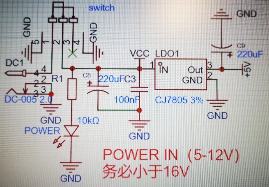
The
power
supply chip used is the CJ7805, which is simple and reliable, and provides high power after conversion, better supporting the power consumption of subsequent circuits. It operates on a 12V power supply with a 5V output. An LED power indicator is included.
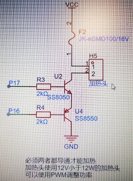
2. Heating and Heat Dissipation:
Considering my experience with the heating head, I again recommend using a low-power heating head. A 1A resettable fuse is added to the circuit for safety and reliability. SS8050 and SS8550 transistors form a complementary circuit; P17 must be high and P16 low for the heating circuit to conduct, providing double protection.
The heating head power can be adjusted using PWM, but this is unnecessary in this project.
The fan is safer than the heating element, so only a fuse was added.
3. Sensor Circuit:
The alcohol sensor found in JLCPCB EDA is CM-A1022S, which uses a 3.3V power supply and is already drawn on the PCB. Because it's 3.3V, while the microcontroller's power supply is 5V, the program processing after ADC sampling needs to be changed. Alternatively, the alcohol sensor section on the PCB can be removed, and the MQ3 alcohol sensor module, powered by 5V, can be used directly.
The temperature sensor only needs a pull-up resistor at the data terminal for stable transmission. Single-bus communication is used, which is simple and safe.

4. Button Description:
There are three buttons: add, dec, and set. The set button connects to the microcontroller's INT0, using interrupts for easy execution. add and dec represent temperature increment and decrement respectively. Pressing set again completes the setting.
Software Description:
Based on a C51 program developed by Keil.
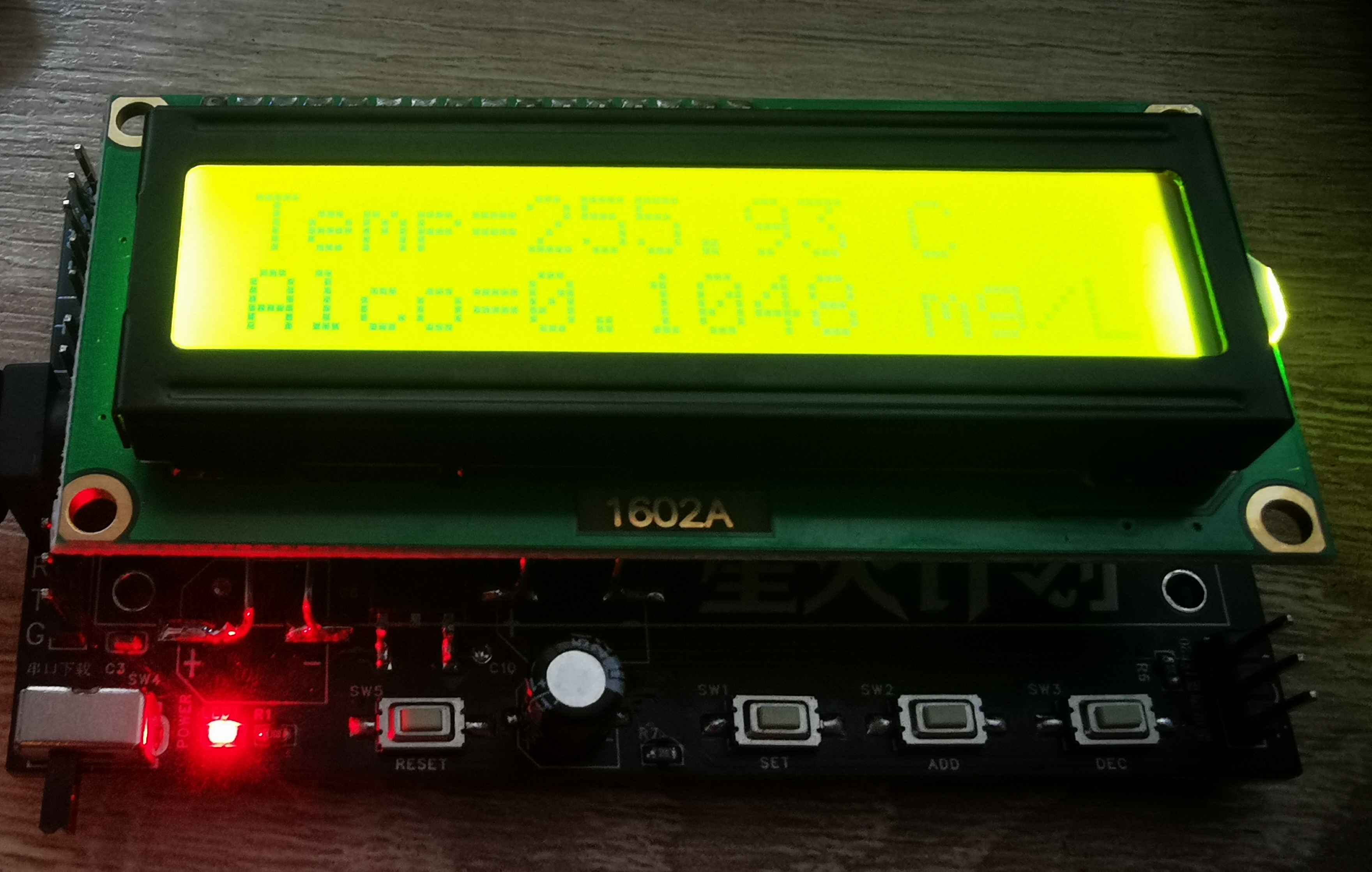
Single-bus control of the temperature sensor, ADC sampling of alcohol concentration, and LCD1602 control and display.
The `set` button is connected to the microcontroller's INT0 pin. An interrupt is used to invoke the setting function, and the plus and minus buttons can only be used in this state. The button is accompanied by a buzzer, and a high-temperature alarm can also be set after the temperature is set (generally, this is not recommended). The `set` button is used to exit or proceed to the next step.
The high-temperature alarm function is disabled when `alarm_temperature` is lower than `SET_temperature` (i.e., `alarm_temperature == 0`).
The main program is as follows, please download the rest from the attachment
/****************************************
all the codes belong to Ampere Jason
if used, pleased declare the source of the program
the design is based on STC12C5A60S2
Crystal oscillator frequency is 12Mhz
if the alarm temperature is 00, the alarming function won't open
*************************************/
//all the header files used
#include
#include
#include
#include "stc12_ADC.h"
#include "LCD1602.h"
#include "delay.h"
#include "18b20.h"
//pins used
sbit set = P3^2;
sbit add = P3^3;
sbit dec = P3^4;
sbit buzz = P1^1;
sbit heat_up = P1^7;
sbit heat_down = P1^6;
sbit fan = P1^5;
//basic variables
unsigned char i,j,s;
unsigned char SET_temp=28;
unsigned char alarm_temp=38;
float Temp;
float alcohol;
//heat handler
void heat(void){
heat_up = 1;
heat_down = 0;
}
void unheat(void){
heat_up = 0;
heat_down = 1;
}
//buzzer handler
void buzz_on_SHORT(void)
{
buzz=1;
DelayMs(250);
buzz=0;
}
void buzz_on_LONG(void)
{
buzz=1;
DelayMs(500);
buzz=0;
}
// transform float or unsigned char into string and display it
void displayfloat(float f,unsigned char x2,unsigned char y2)
{
char buf[6];
sprintf(buf,"%f",f);
LCD_ShowString(buf,x2,y2);
s=0;
while(buf[s] != ''){
buf[s] = '';
s++;
}
}
void displaynum(unsigned char num,unsigned char x3,unsigned char y3)
{
LCD_SetCursor(x3,y3);
LCD_WriteDat(num/10+'0');
LCD_SetCursor(x3,y3+1);
LCD_WriteDat(num%10+'0');
}
//deal with ADC and turn it into readable information
float get_alcohol()
{
float Alcohol;
Alcohol = (GetADC(0)*5)/(2.7*1024);
//Alcohol = 10.67-1.61/(average+0.16);
return Alcohol;
}
void interrupt_init(void)
{
IT0=1;
EX0=1;
EA=1;
}
void exint0() interrupt 0 //(location at 0003H)
{
buzz_on_SHORT();
EA=0; //close interrupt handler
EX0=0;
IT0=0;
while(set==0);
LCD_Clear(); //show setting image
LCD_ShowString("Set Temp=",0,0);
displaynum(SET_temp,0,12);
LCD_ShowString("C",0,15);
LCD_ShowString("Alarm Temp=",1,0);
displaynum(alarm_temp,1,12);
LCD_ShowString("C",1,15);
//key scan
while(1)
{
//set standard temperature
if(add==0){
DelayMs(100);
if(add==0){
buzz_on_SHORT();
SET_temp++;
}
while(add!=1);
displaynum(SET_temp,0,12);
}
if(dec==0){
DelayMs(100);
if(dec==0){
buzz_on_SHORT();
SET_temp--;
if(SET_temp==0){
SET_temp=28;
}
}
while(dec!=1);
displaynum(SET_temp,0,12);
}
if(set==0){
DelayMs(100);
if(set==0){
buzz_on_LONG();
}
while(set!=1);
break;
}
}
//set alarm temperature
while(1){
if(add==0){
DelayMs(100);
if(add==0 && alarm_temp!=0){
buzz_on_SHORT();
alarm_temp++;
}
else{
buzz_on_SHORT();
alarm_temp = SET_temp;
}
while(add!=1);
displaynum(alarm_temp,1,12);
}
if(dec==0){
DelayMs(100);
if(dec==0){
buzz_on_SHORT();
alarm_temp--;
if(alarm_
alarmtemp_temp=0;
}
}
while(dec!=1);
displaynum(alarm_temp,1,12);
}
if(set==0){
DelayMs(100);
if(set==0){
buzz_on_LONG();
}
while(set!=1);
break;
}
}
//show starting image
LCD_Clear();
LCD_ShowString("Temp=",0,0);
LCD_ShowString("C",0,12);
LCD_ShowString("Alco=",1,0);
LCD_ShowString("mg/L",1,12);
set=1;
interrupt_init();
}
void main(void){
//init pins
P0M0 = 0x00; P0M1 = 0x00;
P3M0 = 0x00; P3M1 = 0x00;
P1M0 &= ~0x02; P1M1 &= ~0x02;
P1M0 = 0xe0; P1M1 = 0x00;
unheat();
fan=0;
set=1;
add=1;
dec=1;
buzz=0;
//init ADC, interrupt and LCD
LCD_Init();
LCD_Delay(100);
InitADC();
interrupt_init();
//show starting image
LCD_ShowString("Temp=",0,0);
LCD_ShowString("C",0,12);
LCD_ShowString("Alco=",1,0);
LCD_ShowString("mg/L",1,12);
while(1){
//show the data collected
Temp = ReadTemperature();
LCD_Delay(200);
alcohol = get_alcohol();
displayfloat(Temp,0,5);
displayfloat(alcohol,1,5);
LCD_Delay(200);
//enable temperature controller
if(Temp >= (SET_temp+2)){
unheat();
fan = 1;
}
if(Temp
heat();
fan = 0;
}
if(alarm_temp != 0){
if(Temp >= alarm_temp){
buzz_on_LONG();
DelayMs(500);
} }
}
}
Installation
Instructions:
Use a large bottle of Nongfu Spring water (other brands are also acceptable, no advertising intended). Drill three appropriately sized holes: one for the temperature sensor, one for the heating element, and one for the gas delivery tube. The temperature sensor and heating element need to be immersed in the fermentation liquid. The gas delivery tube must be kept away from the fermentation liquid, and the other end should be liquid-sealed (add a layer of oil to the water surface; personally tested and effective). When you need to measure the alcohol content, pull out the liquid-sealed end of the gas delivery tube, place it on the alcohol sensor, and gently warm it to allow the gas to expand and escape. Measure the alcohol content (there may be errors, for reference only). You can enjoy the fermentation process in about 10 days.
Circuit Diagram: (Not installed, no sensor installed)
Gerber_PCB1_2024-08-23.zip
STC12_fajiao_promax.zip
PDF_Fermentation Monitoring System.zip
Altium_Fermentation Monitoring System.zip
PADS_Fermentation Monitoring System.zip
BOM_Fermentation Monitoring System.xlsx
90782
Cyber Wand_V851s_Bmi088_Keras
Allwinner V851s AI Gesture Recognition Cyber Wand
Cyber Wand_V851s_BMI088_Keras
I. Project Description
This project creatively combines a magic wand with artificial intelligence. Without cloud intervention, the wand itself can recognize and process gestures.
Demonstration video: BiliBili-@realTiX-Cyber Wand
II. Open Source License
GPL 3.0
III. Project Functionality
It recognizes input gestures and can remotely control lights, air conditioning, and even the game Genshin Impact.
You can refer to the open-source code repository to train a model with higher accuracy (currently 92%) and the ability to recognize more characters (currently letters A~Z, numbers 0~9).
This wand uses a Bluetooth serial port pass-through module for communication. You can refer to the communication protocol in the code repository to expand the wand's functionality and develop other Bluetooth terminals to remotely control more Bluetooth-enabled devices.
IV. Project Attributes
This project is being publicly released for the first time and is my original work. This project has not won any awards in other competitions.
V. Project Progress
The project is complete.
Project Update Log:
January 24, 2024, 4 PM: First draft of this article completed.
January 28, 2024, 11 PM: Updated Bilibili video address.
February 1, 2024, 12 PM: Migrated this project to the Spark Program.
September 20, 2024, 4 PM: Modified some descriptions in the article, added cost details, and updated the wand firmware.
VI. Design Principles:
Uses Allwinner V851s to run a self-trained Keras model to recognize gestures;
through the Bluetooth pass-through module on the wand, the recognized data can be sent to Bluetooth-enabled terminals, and mobile phones and computers can also receive the corresponding data.
VII. Software Description
: Software Composition: Uses Keras to train a gesture recognition model, converts it to a TFlite model, and then runs the model through the TFlite C API provided by Google. Since this running method has already been implemented, there are no plans to implement a method to run the model using the NPU interface provided by Allwinner.
The following is the software repository order. Click the blue links to jump:
bmi088 Get baton gesture data
Keras Baton gesture recognition model training
V851s Cyber Magic Wand
Bluetooth controlled simple servo switch light device _HLK-B40
Genshin Impact Bluetooth Android launcher
VIII. Hardware Description
Basic hardware: Allwinner V851s, BMI088, HLK-B40; total cost approximately 80 yuan
Hardware design reference: Yuzukilizard Teak PI Mini AIoT Development Board
IX. Design Notes
1. Download Firmware
①
The firmware file for the magic wand can be downloaded from the project attachments.
Connect the TF card to the computer using a card reader and
use the PhoenixCard software provided by Allwinner to
download the firmware to the TF card according to the steps shown in the figure.

After the firmware download is complete, insert it into the TF card slot. The magic wand takes about half a minute to power on for the first time and about 8 seconds for subsequent power-ups. During
normal power-on, the lights will flash three times and then enter gyroscope initialization, during which the lights will be on, that is, 4 lights will be on.
If the light doesn't flash after a long time, please restart or check the hardware.
You can also connect the data cable to a computer, restart the wand, and use MobaXterm to check the serial port print information to determine the cause . Note that
the Type-C port of this wand is reversible, one for USB-OTG and the other for serial port. Please check the computer driver after plugging it in to determine which direction is the serial port.
② The firmware for the light switch
can be downloaded from the code repository and compiled by yourself, or you can directly download the firmware.
Please refer to the specific method for downloading STC 51 microcontroller programs, which will not be elaborated here.
2. Assembly
①
The 3D file of the shell can be downloaded in the project attachment. Embed the circuit board and battery as shown in the figure below.

②
The 3D file of the light switch bracket can be downloaded in the project attachment.
Assemble the light switch as shown in the figure below. Note that the infrared head needs to be brought out.

Isn't it cool? Technology with fun.
3D model.zip
Gesture Table.txt
202402011232.mp4
Firmware.zip
PDF_Cyber Wand_V851s_Bmi088_Keras.zip
Altium_Cyber Wand_V851s_Bmi088_Keras.zip
PADS_Cyber Wand_V851s_Bmi088_Keras.zip
BOM_Cyber Wand_V851s_Bmi088_Keras.xlsx
90783
[Audio/Video] Hisilicon Hi3516CV610-MINI LINUX Development Board
The HiSilicon HI3516CV610 20S/10B next-generation audio and video codec SOC development board supports H.264, H.265, and SAV C3.0 video encoding, 4K@20/6M@20 encoding performance, a 1T computing power NPU, and a low-power fast-start solution.
The HI3516CV610-MINI 20S/10B Linux audio and video development board
is a new generation audio and video codec SOC from HiSilicon. It supports H.264, H.265, and SAVC 3.0 video encoding, with 4K@20/6M@30 encoding performance,
1T computing power NPU/motion detection intelligent analysis, and MIPI 2Line. Dual-channel sensor, low power consumption, fast start-up, supports AOV, Ethernet interface

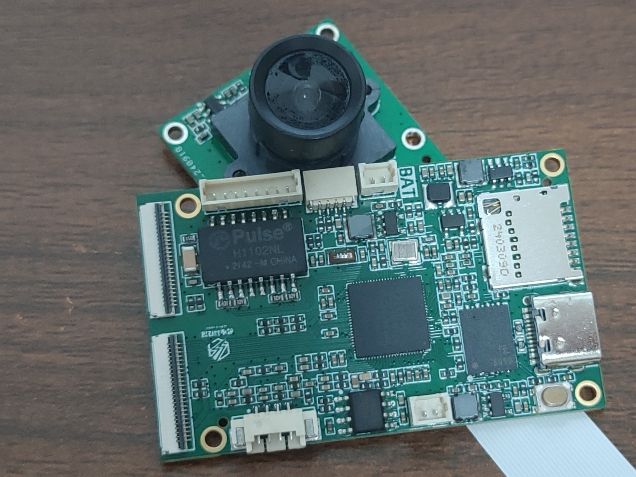

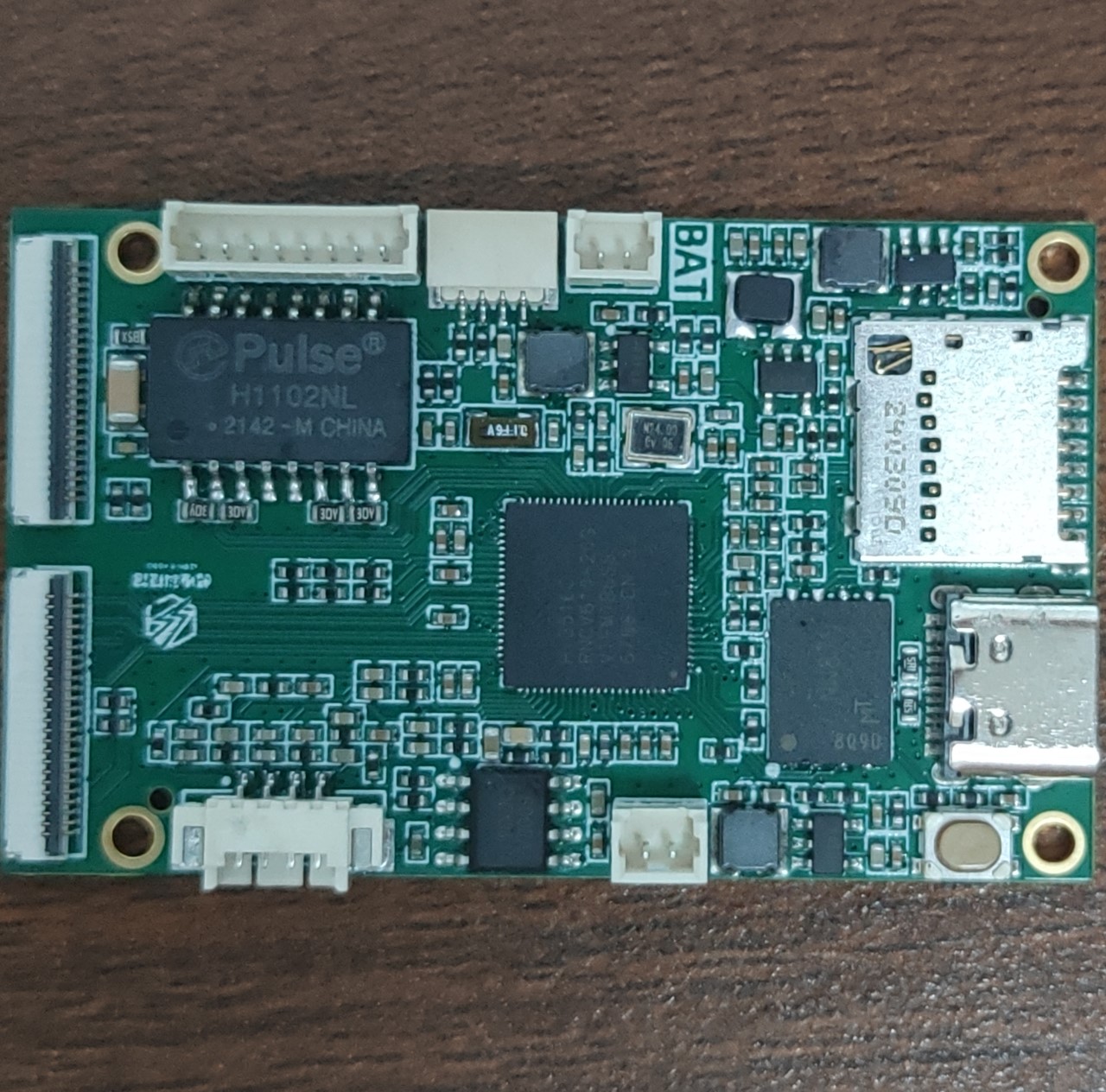
.
Development board link: http://e.tb.cn/h.gHunxWXplKwqTB1?tk=VjUF3j3gCho
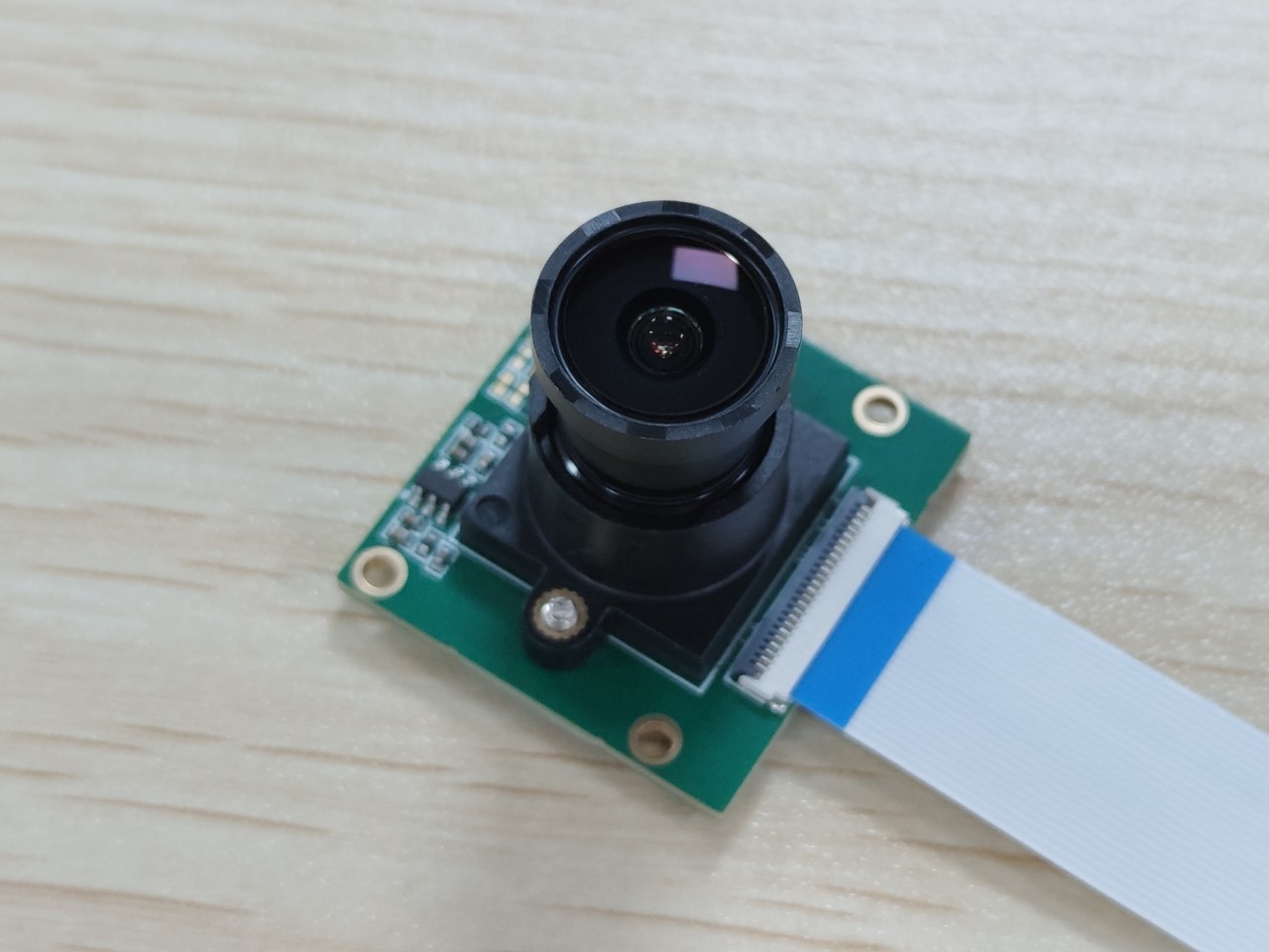
Compatible camera: http://e.tb.cn/h.gstFmdktVWfTQhm?tk=W6BV3j4wXtw
Development board SDK: https://gitlab.com/linux-kodo/hi3516cv610-kodo
Video tutorials (updated as needed): https://space.bilibili.com/390456922/channel/collectiondetail?sid=1280264
Key features:
⚫ 4K@20, 6M@30 resolution
⚫ Real-time binocular access, supports binocular models such as PTZ cameras
⚫ 1T computing power NPU, Transformer feature acceleration, large model edge deployment
⚫ SVAC3.0 Encoding standard, 20% improvement in compression rate
⚫ Smart Encoding 2.0, pixel upgrade, no increase in storage, 4MP 30-bit product can store 5GB per day
⚫ 32x exposure ratio and wide dynamic range, clearer backlighting in shops/lobby
⚫ Improved clarity, motion blur, face and license plate effects in low-light scenes
⚫ 15-meter voice pickup, 3-5 meter intercom, crying detection in home scenes
⚫ AOV low-power solution
⚫ OpenHarmony system and ecosystem
processor core
⚫ Supports ARM Cortex-A7 MP2
⚫ 950MHz clock speed
⚫ Supports 32KB I-Cache, 32KB D-Cache, 128KB L2 cache
⚫ Supports Neon and FPU intelligent engines
⚫ Neural Processor NPU
- Supports 1TOPs computing performance - Supports hundreds of mainstream algorithms in the industry, enabling customers to quickly commercialize - Supports Transformer feature acceleration, with a built-in dedicated multimodal large model - Tools support efficient model production and evolution - Built-in algorithms for face, human, vehicle, package, and pet detection, etc.
⚫ IVE2.5 upgraded operator, supporting motion detection, perimeter protection, tracking, perspective transformation, video diagnostics, and various intelligent analysis applications. AI ISP Processing
⚫ Supports basic ISP functions - Supports dynamic bad pixel correction - Supports 3A (AE/AWB/AF) functions, with user-adjustable parameters - Supports lens shading correction
⚫ Supports high dynamic range - Supports two-frame WDR fusion - Supports Advanced Local Tone Mapping - Supports strong light suppression and backlight compensation
⚫ Clarity and Noise Reduction - Supports fixed pattern noise removal (FPN) - Motion region enhancement algorithm - Supports temporal and spatial noise reduction - Supports multi-level motion detection
⚫ Color Management and Contrast Enhancement – Supports Purple Fringing Removal 2.0 – Supports Key Color Enhancement – Supports Local Dynamic Contrast Enhancement – Supports Dehazing Functionality
⚫ PQ Tool 1.2
PDF_【Audio/Video】HiSilicon Hi3516CV610-MINI LINUX Development Board.zip
Altium_ [Audio/Video] HiSilicon Hi3516CV610-MINI LINUX Development Board.zip
PADS_【Audio/Video】HiSilicon Hi3516CV610-MINI LINUX Development Board.zip
BOM_【Audio/Video】HiSilicon Hi3516CV610-MINI LINUX Development Board.xlsx
90784
Efficiency Booster - Center Console Based on ESP32 + Serial Port Screen
After three months of research and overcoming numerous obstacles (of my own making), I finally managed to create an engineer's efficiency tool – the Central Control Console V0.9 – using a "domestic EDA platform + domestic serial port screen + domestic 32-bit chip"... There are still many areas for improvement.
Video Links:
A "Desktop Control Console" Composed of a Serial Port Screen and ESP32, Costing Only a Few Tens of Yuan - Bilibili
Host Computer Software Code (Please feel free to discuss any unclear points)
https://gitee.com/lsy330586/ESP32-python.git
Microcontroller Code
https://gitee.com/lsy330586/esp32-serial_port_screen.git
Project Introduction
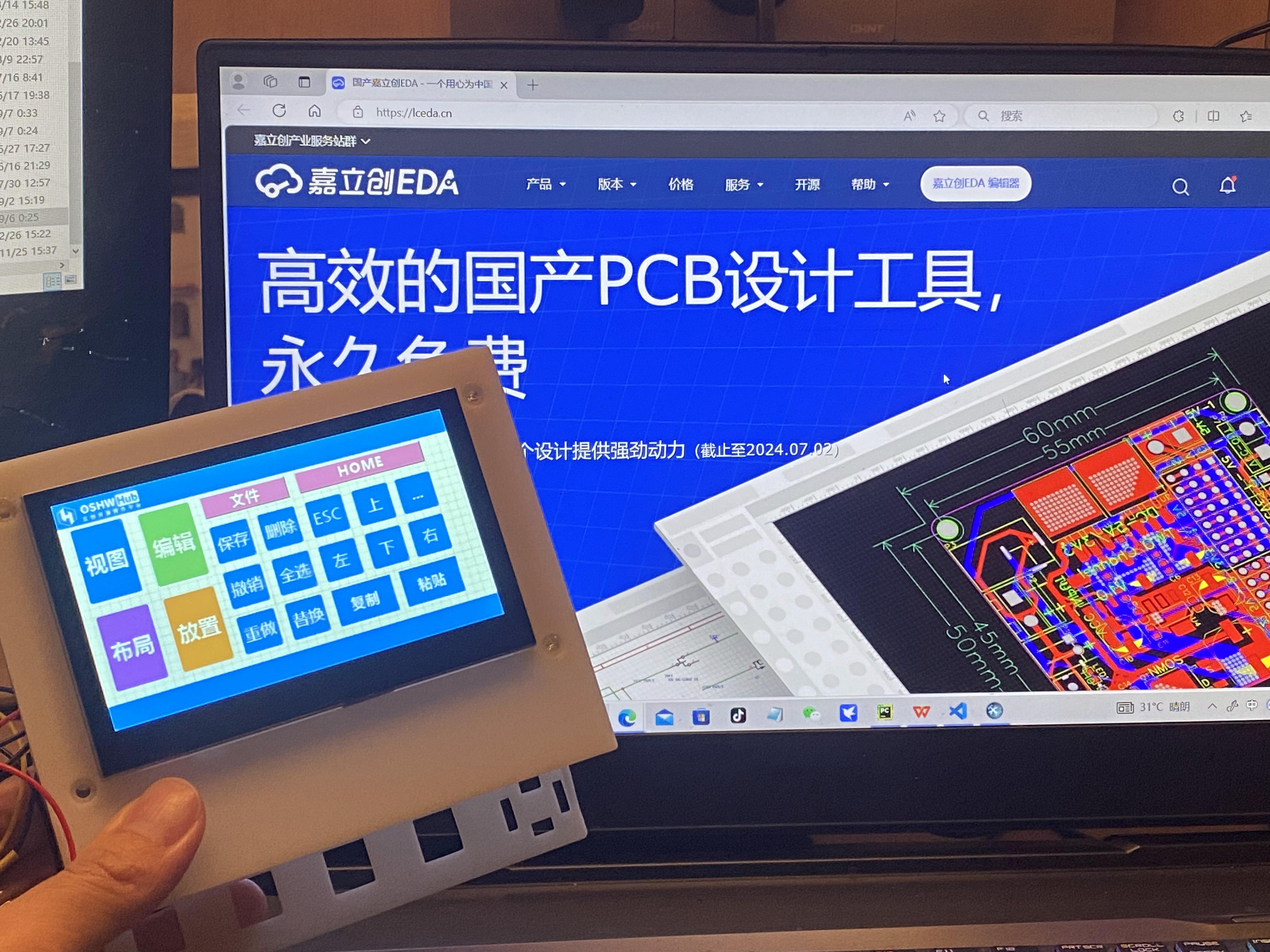

This project builds a "central control console" based on the ESP32-S3 chip and a Taojingchi serial port screen.
The main reason for choosing this chip and serial port screen is its simple hardware design, which can shorten the development cycle of the HIM and microcontroller programs, allowing us to focus more on the development of the host computer software.
It's worth mentioning that AI plays a significant role in the development of the microcontroller and host computer programs;
the circuit part and the serial port screen are not complex, anyone can do it!
The project
currently supports the following functions:
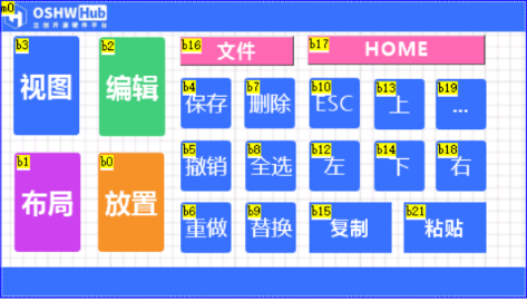
Touchscreen buttons: Open computer software, log in to websites, shortcut keys (customizable) such as keyboard AZ, combination keys: "CTRL+C", "CTRL+V", "SHIFT+TAB".
Application scenarios:
Customized shortcut keys: "LCSC EDA shortcut keys", "CapCut shortcut keys", "TikTok Live Companion", "OBS", "keil_5", etc. ...
I will upload video tutorials in the
future. Future implementations include:
Smart furniture central control, voice input AI to text conversion, universal remote control function...
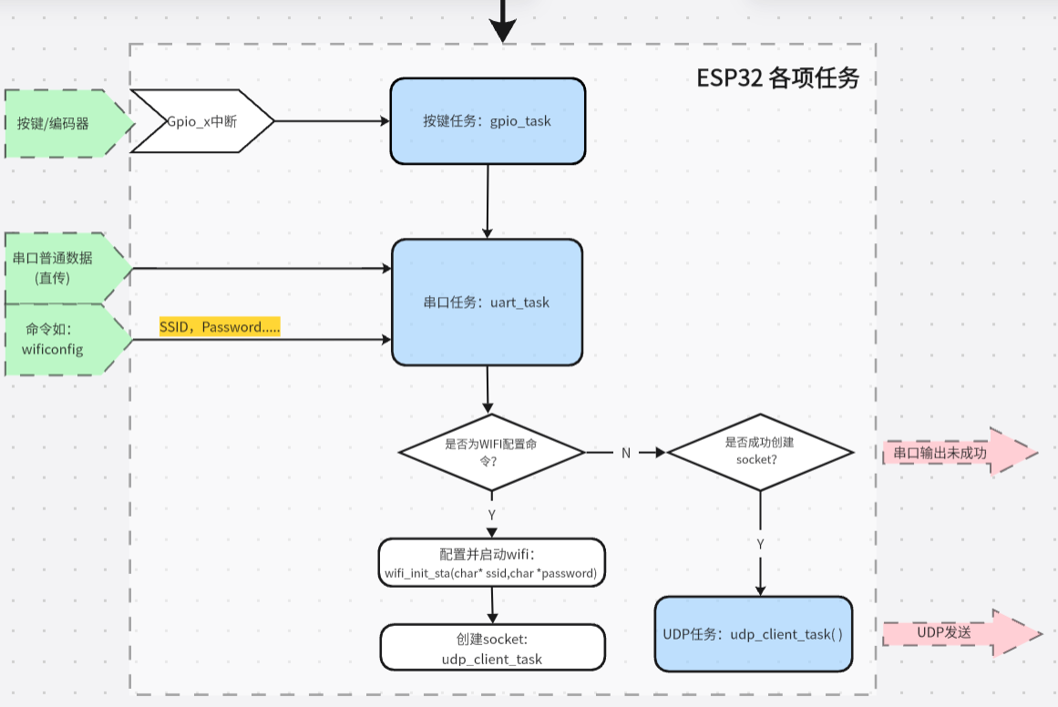
Implementation principle:
Data flow Image 1:
Taking pressing the "copy" key as an example
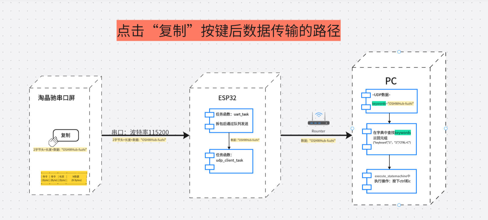
Protocol:
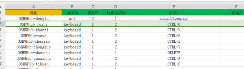
Python dictionary {}
Key: Key
Value: {"Function code", "Operation", "Total data n", "Parameter 1", "Parameter 2", "Parameter 3"}
1. It is worth mentioning that the data sent by the button (serial port screen)
2. ESP32 receives the serial port data and then forwards it to the host computer via UDP
3. The host computer receives the data;
3. Compare the following key values in the host computer's "dictionary";
if found, return a tuple {"function code", "operation", "total data n", "parameter 1", "parameter 2", "parameter 3"}.
Taking "copy" as an example, the key value is **"OSHWHub-fuzhi"**. Return {"keyboard", "1", "2", "CTRL+C", " ", "}}.
- "function code": keyboard represents simulated keyboard operation, and can also be url / openfile / pccontrl..... etc., which can be customized;
**- "operation":** The number "1" represents pressed, and can also be defined as long press, short press, etc.
- "total data n": "2" is (not the number of parameters), because two key values CTRL and 'C' are pressed;
- "parameter 1": two key values
- "parameter 2": omitted
- "parameter 3": omitted
item parameter
1.
Main control chip: adopts ESP32S3 series chip, based on FreeRTOS operating system, supports rapid UDP development.
2.
Display: Uses a Taojingchi serial port display with official HMI software, providing a graphical interface to simplify the development process of functions such as buttons, sliders, and text boxes; baud rate is 115200; only a small amount of very simple logic code is needed, as many functions are already integrated and encapsulated, making it very powerful.
3.
Mechanical Keyboard: Integrates specific mechanical keys, suitable for frequently used operations such as copy, paste, spacebar, etc., improving operational efficiency.
4.
Encoder: Employs an EC11 encoder, suitable for adjusting continuously changing parameters, such as volume, brightness, and zoom.
Principle Analysis (Hardware Description)
This project consists of the following parts: power supply, LCSC ESP32S3 main control development board, button circuit including blue axis mechanical buttons, EC11 encoder,
gyroscope, and Taojingchi serial port screen
. The most important parts are the ESP32 development board and the Taojingchi serial port screen.
The development board provides Wi-Fi connection, control, and data transmission functions, and can process the data from the serial port screen and send it to the computer via TCP/IP.
The Taojingchi serial port can quickly build buttons and program them via serial port...
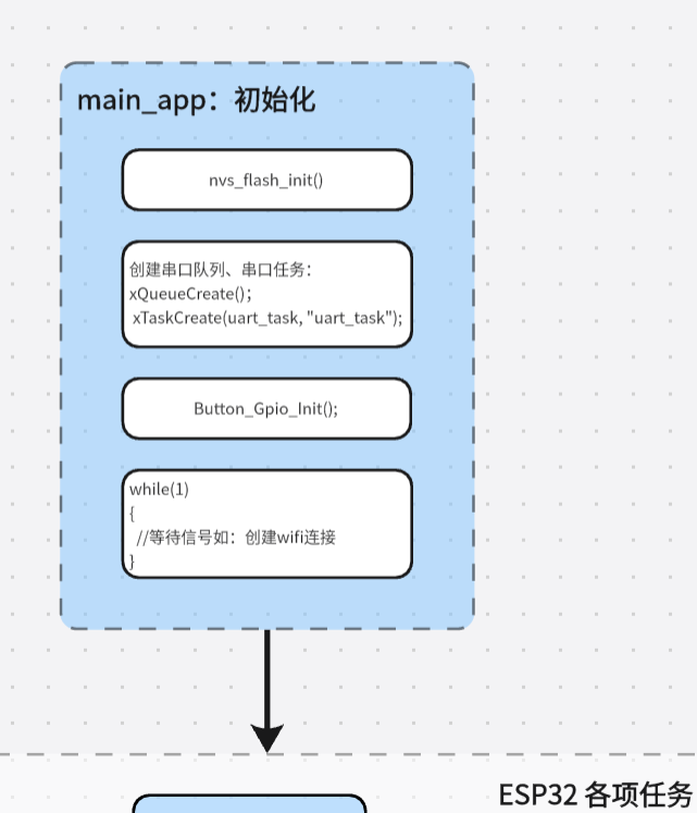
ESP32 software flowchart:
Python function flowchart:

Hardware circuit
example diagram 1 -- Mechanical button circuit:
A 10K pull-up resistor raises the GPIO pin to 3.3V. The microcontroller detects whether the button is pressed through a falling edge interrupt of the GPIO.
I tried to reduce interrupts from the hardware side. I added a 5pF capacitor between the GPIO input pin and GND for debouncing.
Other tutorials give 100nF (0.1u), but after testing, I found that 5pF-10pF works best? Is this how mechanical buttons are supposed to be? I haven't bought an oscilloscope yet, so I'd appreciate some advice...
Regarding the effect: the mechanical buttons bounce 40-50 times after being pressed. After adding a capacitor, the bounce is reduced to 5-10 times per press, a significant debouncing effect. A short 50ms delay in the software further eliminates the bounce.
Based on my testing, the power supply also significantly affects the button's bounce; the bounce varies depending on the USB port on the same computer...

Example image 2 -- EC11 Rotary encoder circuit: This example circuit

was built according to the official reference.
Example Figure 3 – ESP32S3R8N8 development board: The circuit
uses the development board recommended by LCSC. Since this version uses jumper connections, the selection of I/O ports is relatively flexible and can be modified at any time.

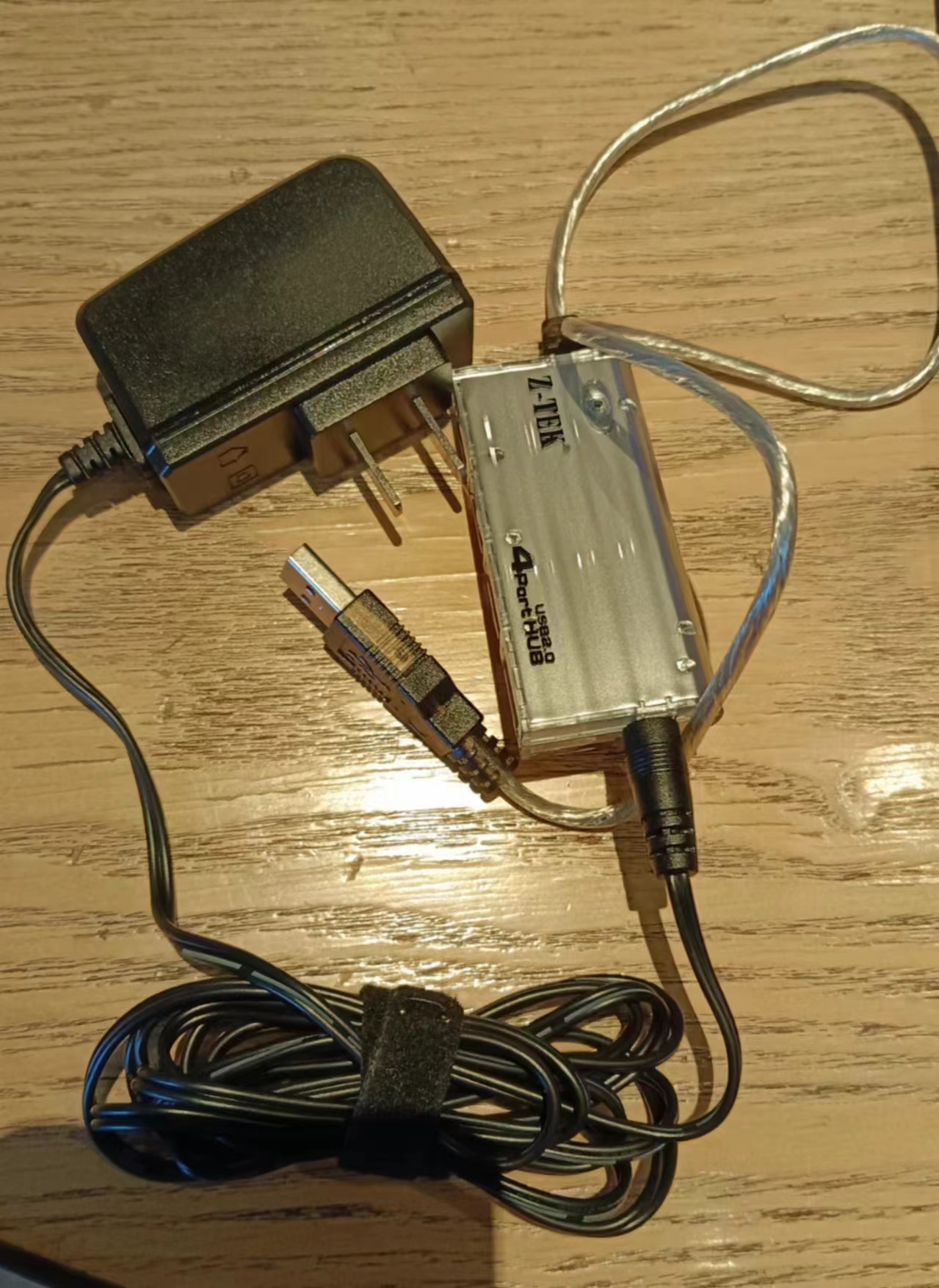
Example Figure 4 – Power supply circuit:
We'll use the existing power supply for now and create our own in the next version. The Wi-Fi chip itself is quite power-intensive, and there's also a microcontroller on the serial port screen, so the power supply needs to be stable.
Example Figure 5 – Serial port screen

circuit: The official schematic and circuit for the serial port screen are provided. The screen inherits a microcontroller chip.
Example Figure 5 – Shell:
Host computer software code
: https://gitee.com/lsy330586/ESP32-python.git
Microcontroller code
https://gitee.com/lsy330586/esp32-serial_port_screen.git
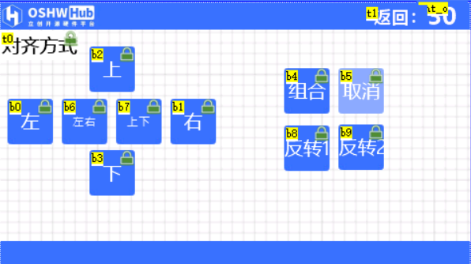
Serial Port Screen Creation Tutorial ***
1. Create Protocol
2. Drag in Buttons, Write a Line of Code for Each Button:
printh ......
2-2. Configure WiFi: wificonfig with keyboard
selection (Keyboard A)
2-3. Place Resistors and Capacitors Page Creation, Add Timer for Exit
3. Beautify Buttons and Background;
Arrange Them
4. Add Small Functions
September 6th_1080p_4000kbs.mp4
PDF_Manually Hand-Controlled Efficiency Tool - Center Console Based on ESP32 + Serial Port Screen.zip
Altium - A hand-operated efficiency powerhouse: a center console based on ESP32 + serial port screen.zip
PADS - A handheld efficiency tool - a center console based on ESP32 + serial port screen.zip
BOM_Manually Hand-Controlled Efficiency Tool - Center Console Based on ESP32 + Serial Port Screen.xlsx
90785
ESP-KeyBoard
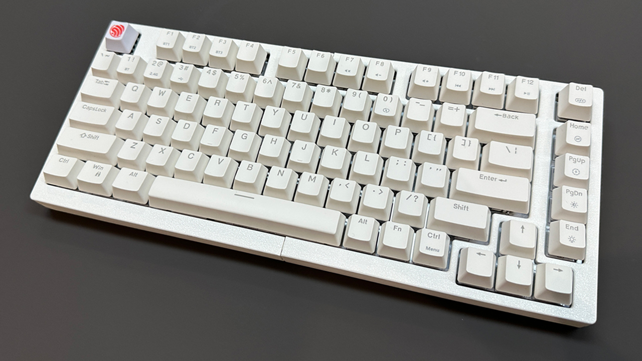
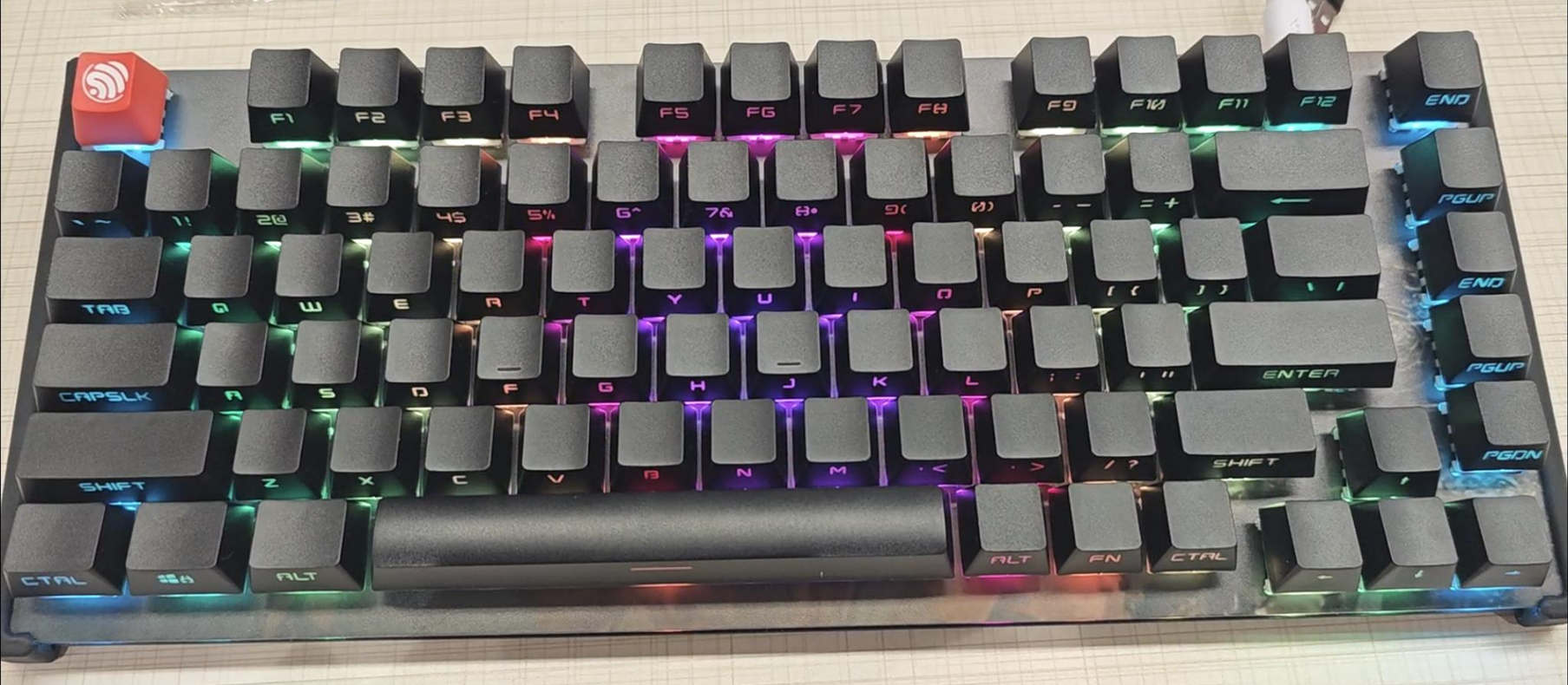
The ESP-KeyBoard is a high-performance custom keyboard using the ESP32S3 as its main controller. It supports full-key rollover, hot-swapping, Bluetooth/USB dual-mode output, and over 40 local lighting effects with Windows 11 lighting synchronization. It comes with a built-in 4000mAh lithium battery.
Project Overview:
The ESP-KeyBoard is a high-performance, customizable keyboard using the ESP32S3 as its main controller. It supports full-key rollover, hot-swapping, Bluetooth/USB dual-mode output, and over 40 local lighting effects with WIN11 lighting synchronization. Equipped with a 4000mAh lithium battery, the ESP32S3's excellent power consumption control significantly extends the keyboard's wireless usage time.
Key features
include matrix key scanning, full-key rollover, a 20kHz software scan rate,
and low-power scanning that only scans when in use.
USB reporting reaches a 1kHz polling rate, and Bluetooth reporting reaches a 133Hz polling rate.
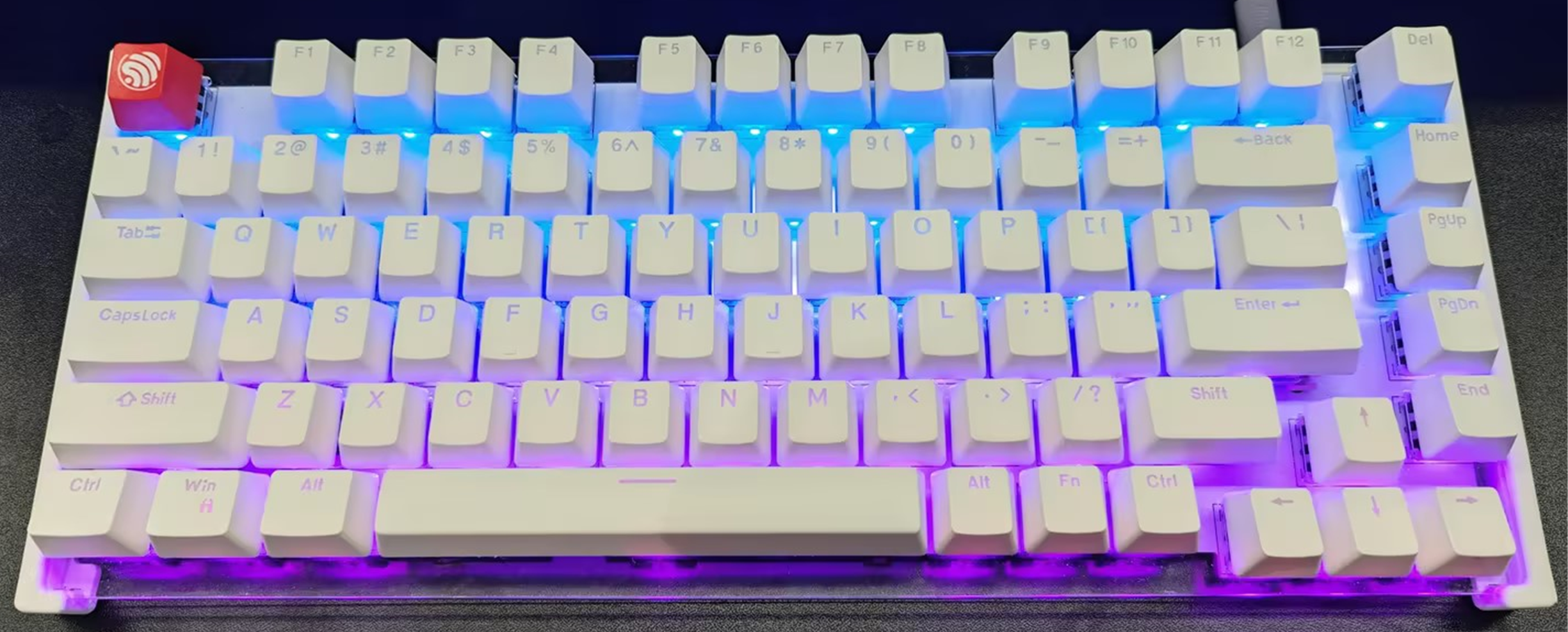
It supports over 40 local lighting effects and
WIN11 dynamic lighting effects, easily synchronizing with other devices.
Highly customizable with hot-swappable switches,
the keyboard's overall structure is fixed around the edges with a suspended center, resulting in a softer, more responsive feel.
Version Update Log:
2024-09-19:
Optimized structure:
Reduced use of 3D printing materials, making replication easier!
The keyboard architecture has been optimized for a more responsive and comfortable user experience
. The back and front panels use acrylic printed panels, allowing for easier customization of desired patterns.
July 2, 2024:
Added the 03-ESP32-S3 control board_V1.1:
Added a 32.768K crystal oscillator, reducing power consumption when entering light sleep via BLE connection (reducing standby current by approximately 2mA).
Added total power control for the WS2812 LED group, allowing complete disconnection of WS2812 power supply when using battery power (reducing standby current by approximately 40mA).
Added battery voltage detection.
The hardware design
uses the same 75-row hard drive layout as Zhihui Jun, but the keyboard scanning method has been changed to a matrix keyboard scanning method. This scanning method is lower in cost and, by enabling key interrupts, can detect whether keys are pressed in real time, thus determining whether the keyboard is working. This ensures extremely low standby power consumption.
The 6x15 matrix keypad
uses a row-output, column-input scanning method, with a maximum scanning frequency of 20kHz
. It is woken up via level-triggered activation, ensuring the keyboard only operates when a key is pressed, thus reducing power consumption.

The main control board and keyboard PCB are designed separately, allowing for future redesign of the main control board and the addition of features such as a USB hub and upgrade modules (future replacement with ESP32H4). This reduces the cost of keyboard updates and iterations. The software
design
references the QMK core logic, easily enabling modification of keyboard mappings and supporting various keyboard hotkeys, such as volume + and volume -.
Key combinations
:
FN + F1
USB mode;
FN + F2
Bluetooth mode;
FN + F10
Volume on/off ;
FN + F11
Volume down;
FN + F12
Volume up;
FN + Home
Toggle local lighting color;
FN + PgUP
Toggle local lighting effect forward ;
FN + PgDN
Toggle local lighting effect backward;
FN + END
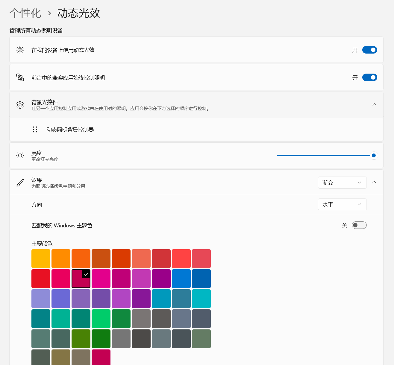
Toggle W11 dynamic lighting effect; FN +
Spacebar
Toggle local lighting effect; FN + ↑ Increase local lighting brightness; FN + ↓ Decrease local lighting brightness ; FN + ← Decrease local lighting speed; FN + → Increase local lighting speed. Regarding Windows 11 dynamic lighting effects : Currently, each manufacturer's RGB peripherals have their own lighting control software, making it difficult to display the same RGB lighting effect across all peripherals. Windows 11 supports standard HID-based lighting control. Devices only need to add HID dynamic lighting effect functionality to their firmware to allow Windows to control their own modes. Due to printer size limitations, the 3D shell features a split design. Those with the skills can assemble it into a single unit. Bill of Materials: 1 * M3 x 3mm brass nut, 1 * M3 x 4mm screw, 4 * 12mm diameter plastic feet, 2mm thick foam tape, 2mm thick plastic tape. Project code: https://github.com/espressif/esp-iot-solution/tree/master/examples/keyboard Future plans include supporting 2.4GHz main controllers, replacing them with the ESP32H4 for better power consumption control, modular components, screen, USB docking station, etc.


keyboard_light.gif
ESP-Keyboard case + plate.zip
Shell file_v1.1.zip
PDF_ESP-KeyBoard.zip
Altium_ESP-KeyBoard.zip
PADS_ESP-KeyBoard.zip
BOM_ESP-KeyBoard.xlsx
90786
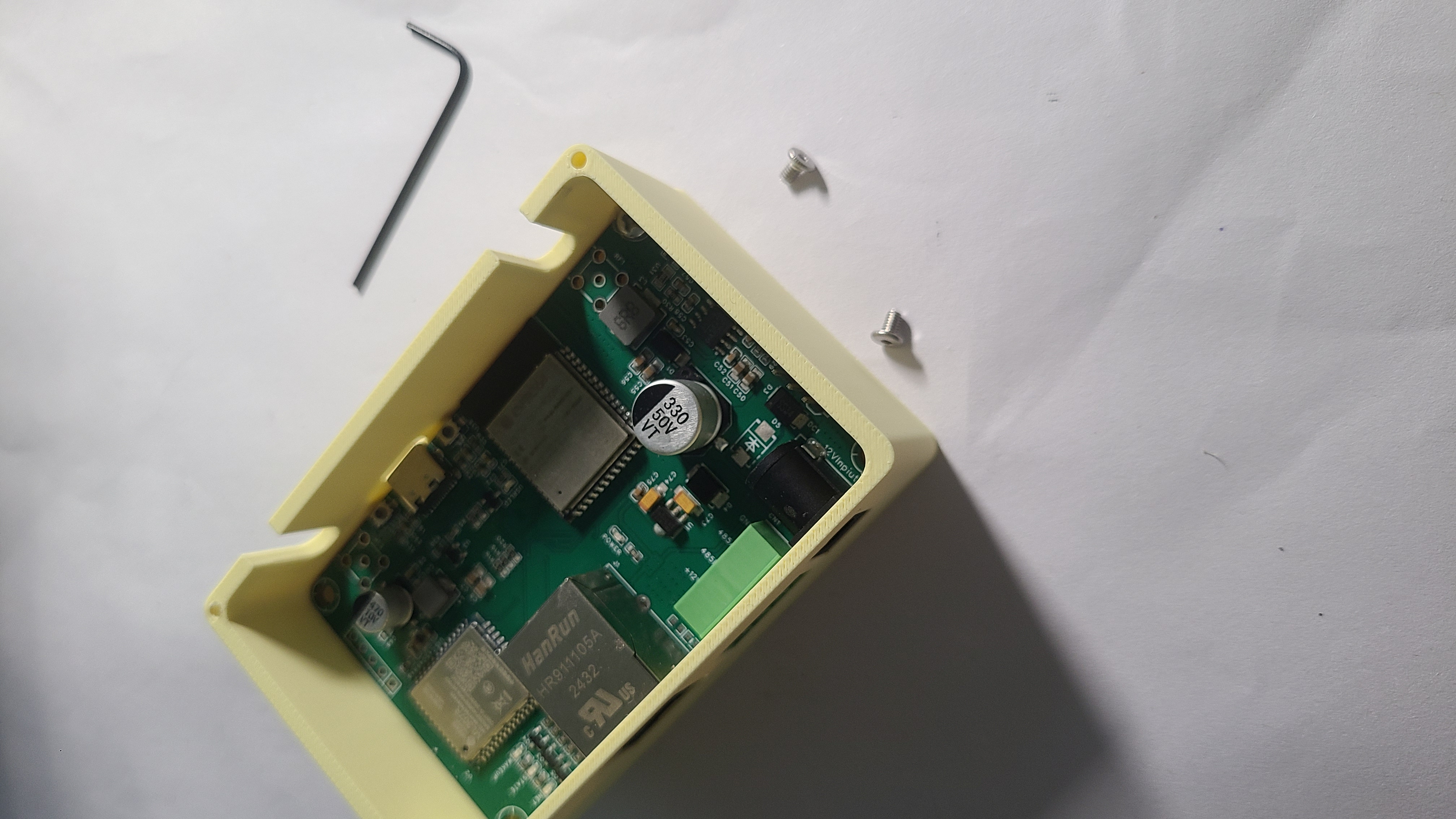
ESP32 RS485 DTU with Ethernet and 4G
A DTU data acquisition unit using an ESP32 as the main controller, with Ethernet and 4G modules.
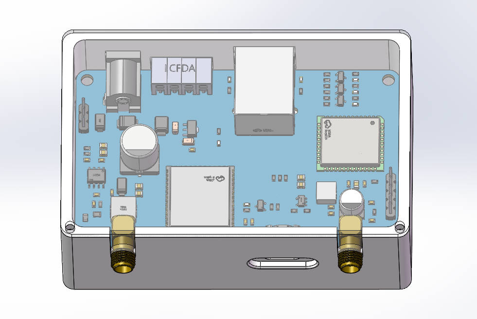
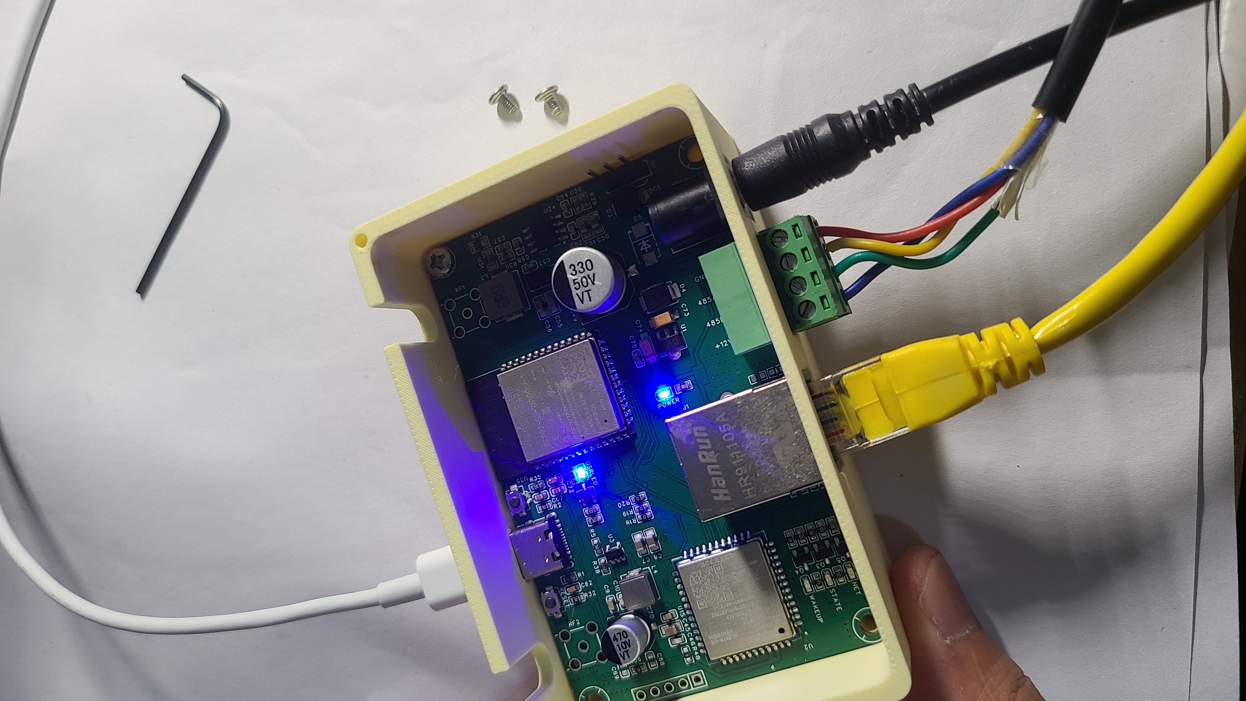
This project introduces a DTU box based on the ESP32-S3 microcontroller,
using the ESP32-S3 as the main controller. It allows for network connectivity via Ethernet, 4G, and Wi-Fi, transmitting collected RS485 device data to a DTU box at a target IP address. The project offers flexible development options for the ESP32, including IDF, Arduino, and MicroPython. Wired or wireless connections are supported. Power can be supplied via 5V USB or a wide voltage DC power supply. A configurable serial port with a target IP address facilitates easy data transmission to the target platform. The DTU box is designed to fit standard dimensions, serving as a data development and verification platform.
I. Networking Modes
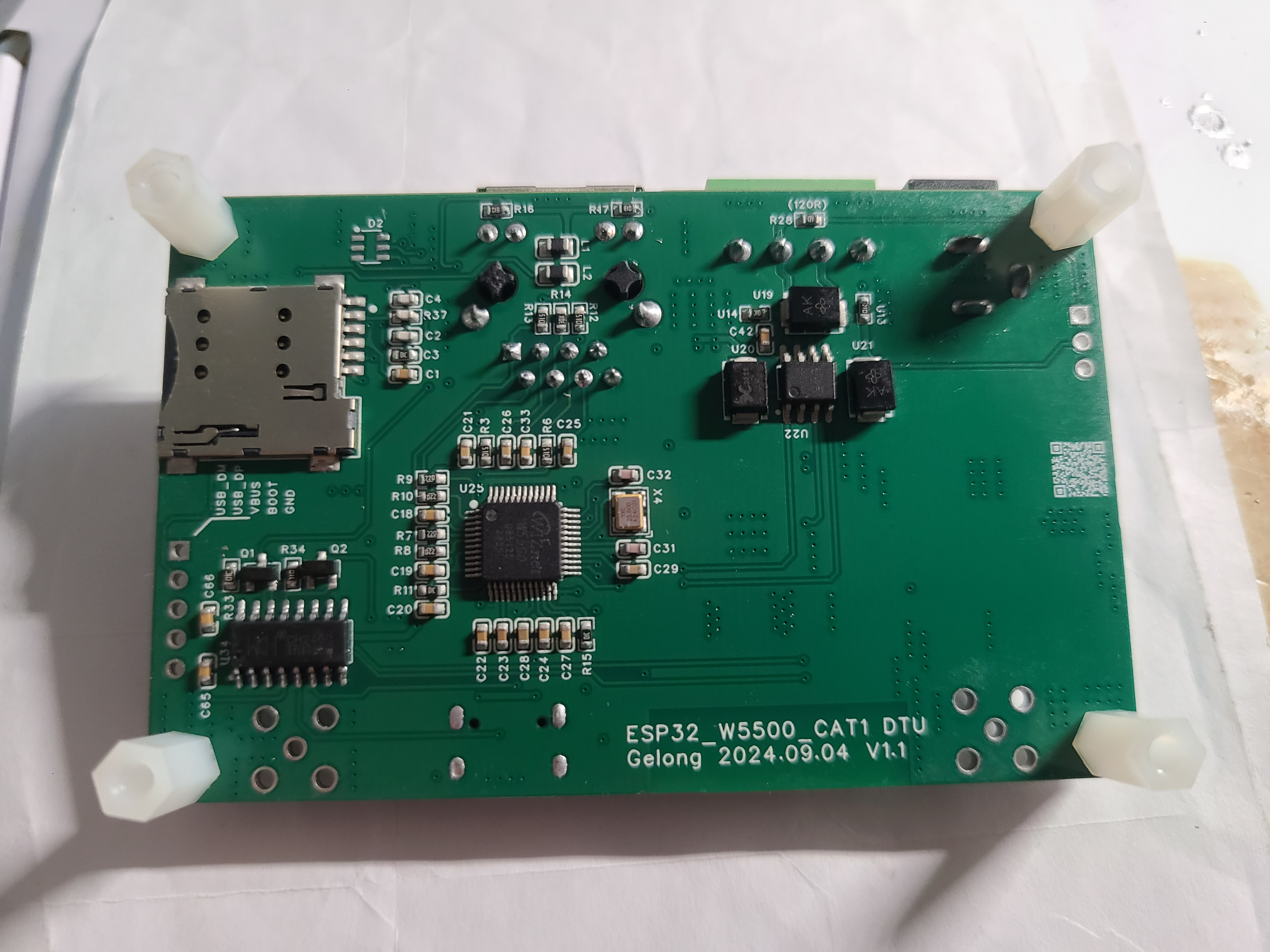
1. W5500 Ethernet Connection
: Ethernet provides a stable wired connection. Simply connect the box and router with a network cable for easy network connectivity. The W5500 uses an SPI interface for high data transfer rates, and the driver code is readily available for various driver methods. The W55500 has a built-in complete TCP/IP protocol stack, easily implementing network protocols such as TCP, UDP, and HTTP, and also supporting the more flexible MQTT protocol. The use of the W5500 chip reduces the network load on the main processor. Although the ESP32S3 chip itself can connect via Wi-Fi, wired Ethernet connections are more stable and can be used as a high-speed backup solution.
2. ML307R-4G Connection:
The ML307R is a newly launched 4G CAT1 module from China Mobile. It can be developed using AT commands, which is more lightweight than Ethernet protocol drivers. AT commands include instructions for data transmission to common telecom AEP platforms, Onenet platforms, or private MQTT personal server platforms, and can also be easily used for network development using TCP, UDP, and HTTP protocols. As a wireless wide area network connection, the 4G module is not limited by location, as long as a 4G network can be received.
3. WIFI Connection:
WIFI connection is the most readily available networking method and is an inherent networking method of the ESP32. It offers the best compatibility during development and is the most widely used and easiest to obtain among all development methods.
II. Power Supply Modes:
1. 5V USB Power Supply:
It can be directly powered using the 5V USB port. An adapter resistor is added to the interface. It can be directly connected to a computer via a USB data cable, serving both power supply and data download functions.
2. DC Wide Voltage Power Supply:
It uses a 12V to 24V DC power supply. This wide voltage supply can fully handle the peak current spikes that may occur during the instantaneous startup and connection of 4G, Ethernet, and WIFI modules. The TPS54331 chip is used for voltage conversion, supporting a maximum current drive capability of 2A.
III. Interfaces:
1. USB Interface:
The USB interface serves as the program download and debugging interface, directly connecting to the computer. The serial port chip used is CH340C, designed with an automatic download circuit.
2. Ethernet Interface:
A standard RJ45 interface.
3. The RS485 interface
features a TVS protection chip and has four wires: VCC (12V), 485A, 485B, and GND. It includes a 120Ω terminating resistor, and the jumper cap position can be changed to select whether to use it.
4. The antenna
is a commonly used rod-shaped 4G antenna with good gain.
5. The power supply interface
uses a DC power connector.
IV. Pictures and Attachments

ESP32_DTU_3D file.zip
PDF_ESP32 RS485 DTU with Ethernet and 4G.zip
Altium_ESP32 RS485 DTU with Ethernet and 4G.zip
PADS_ESP32 RS485 DTU with Ethernet and 4G.zip
BOM_ESP32 RS485 DTU with Ethernet and 4G.xlsx
90787
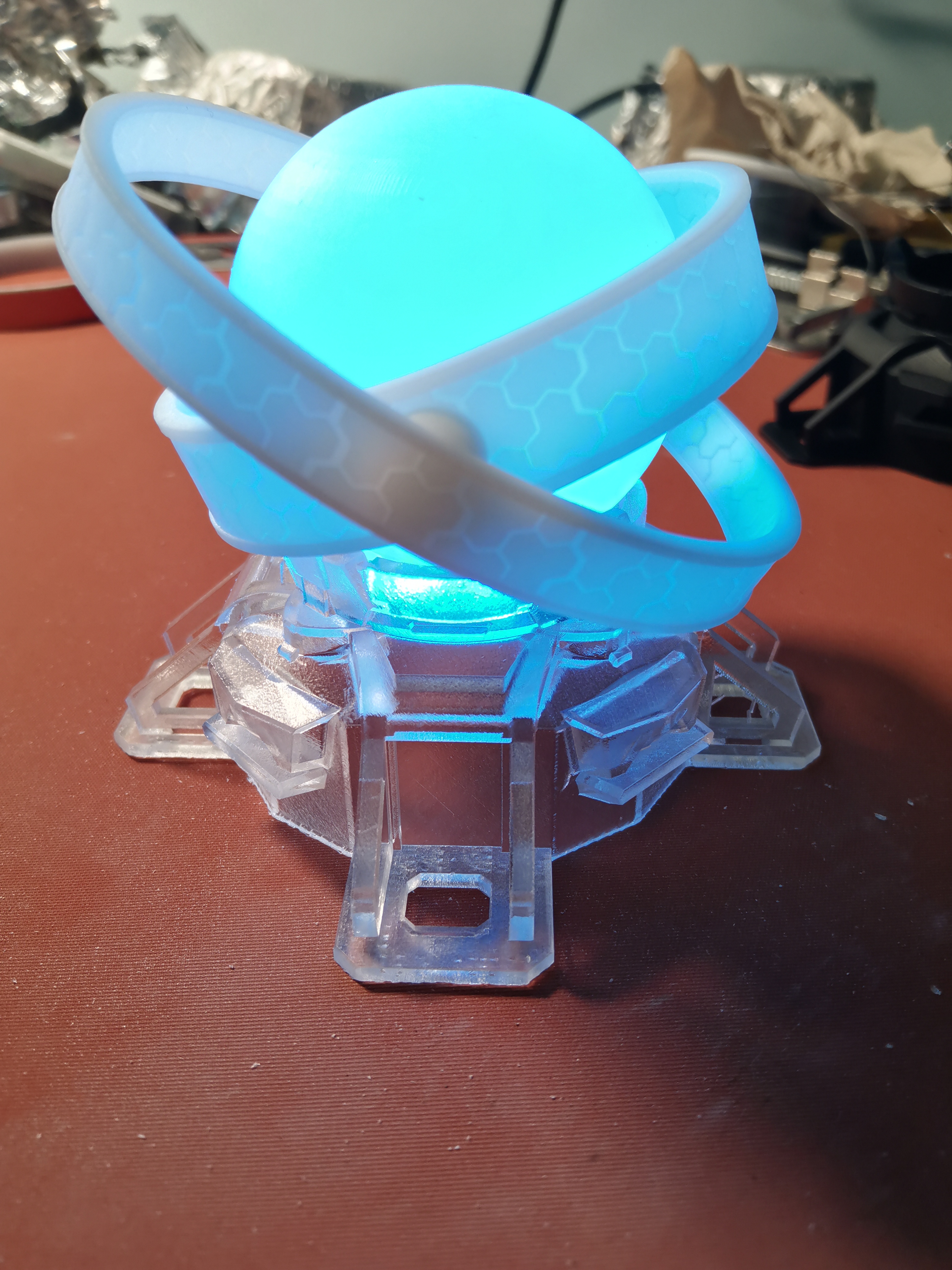
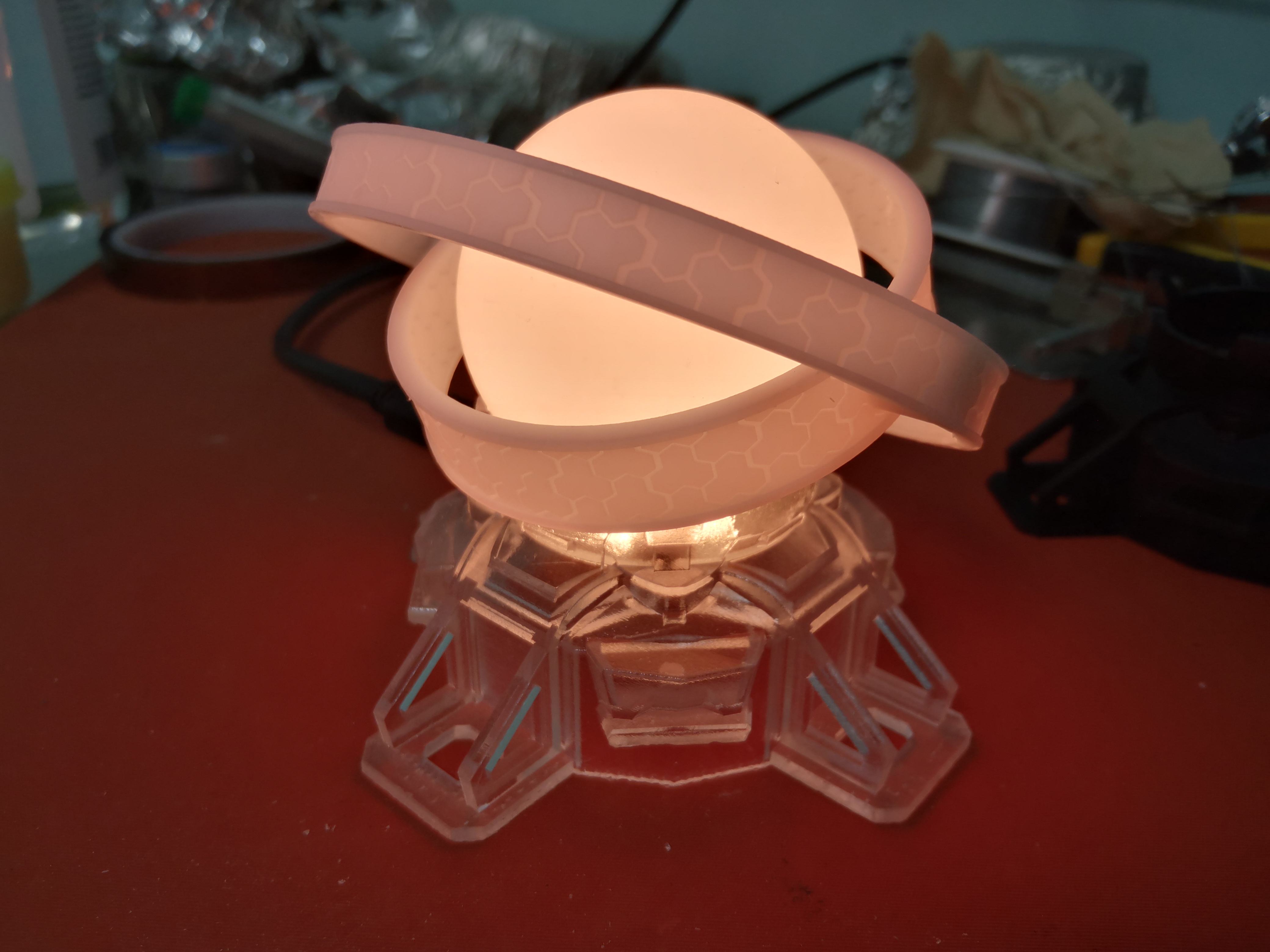
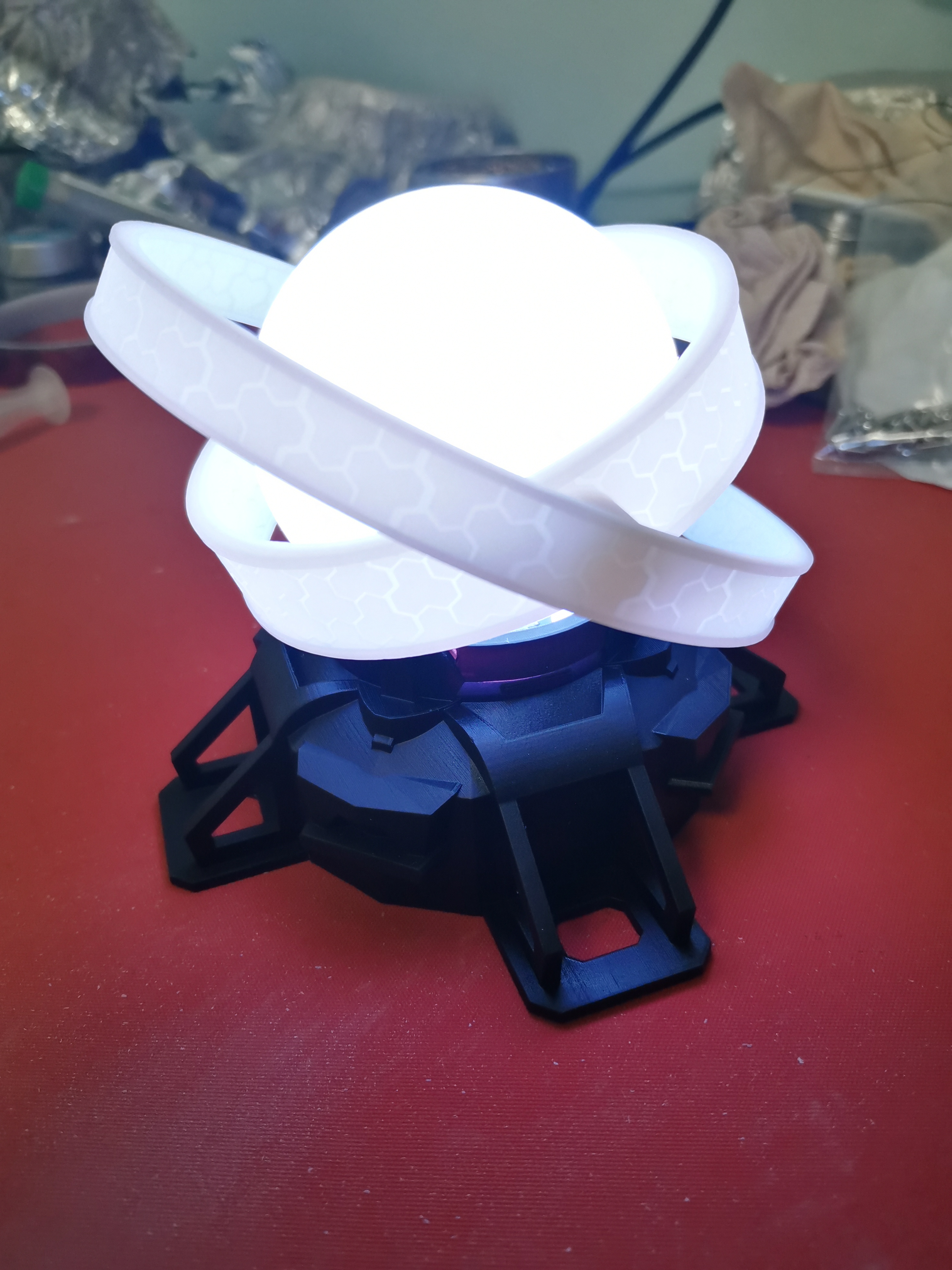
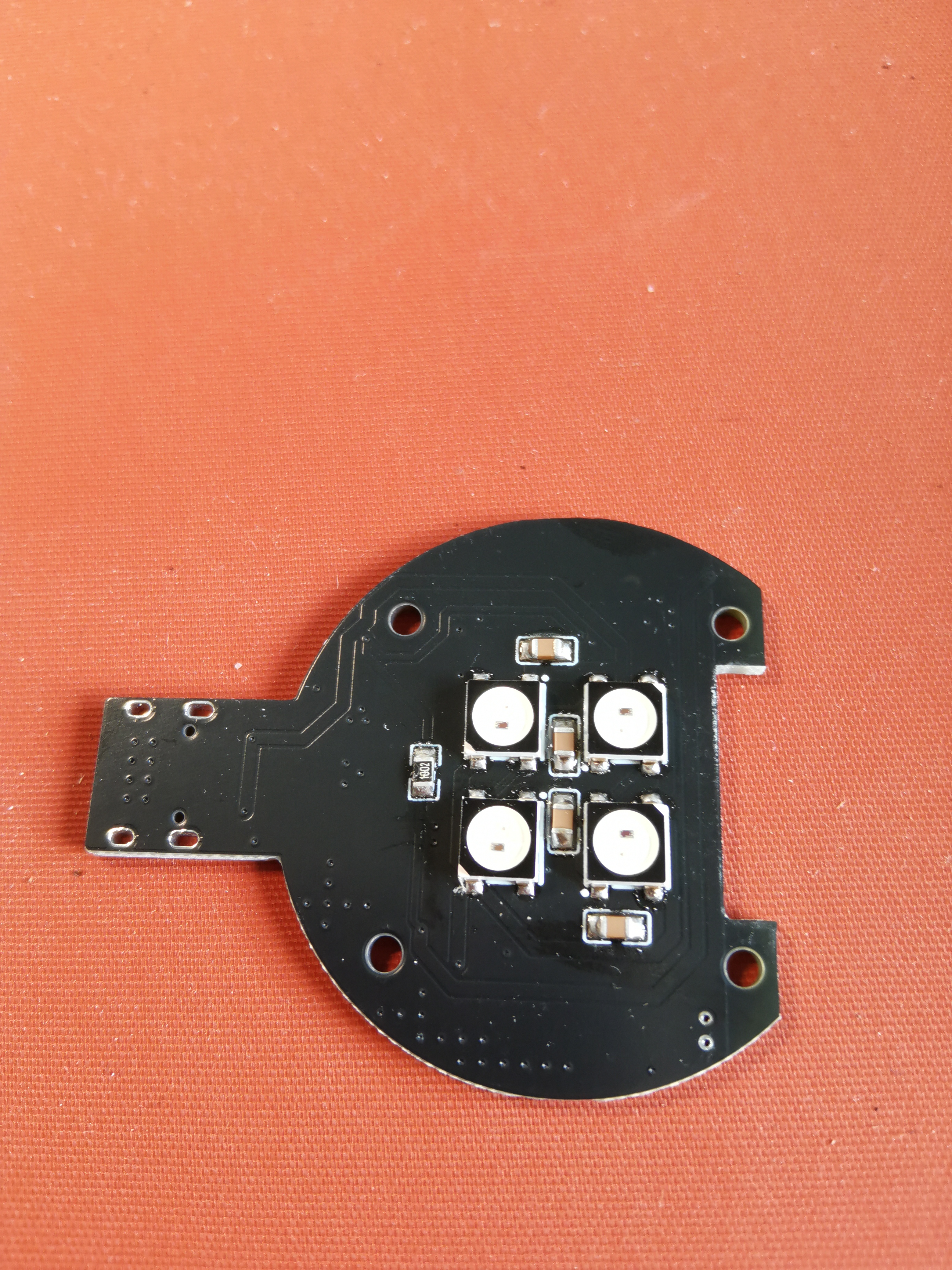
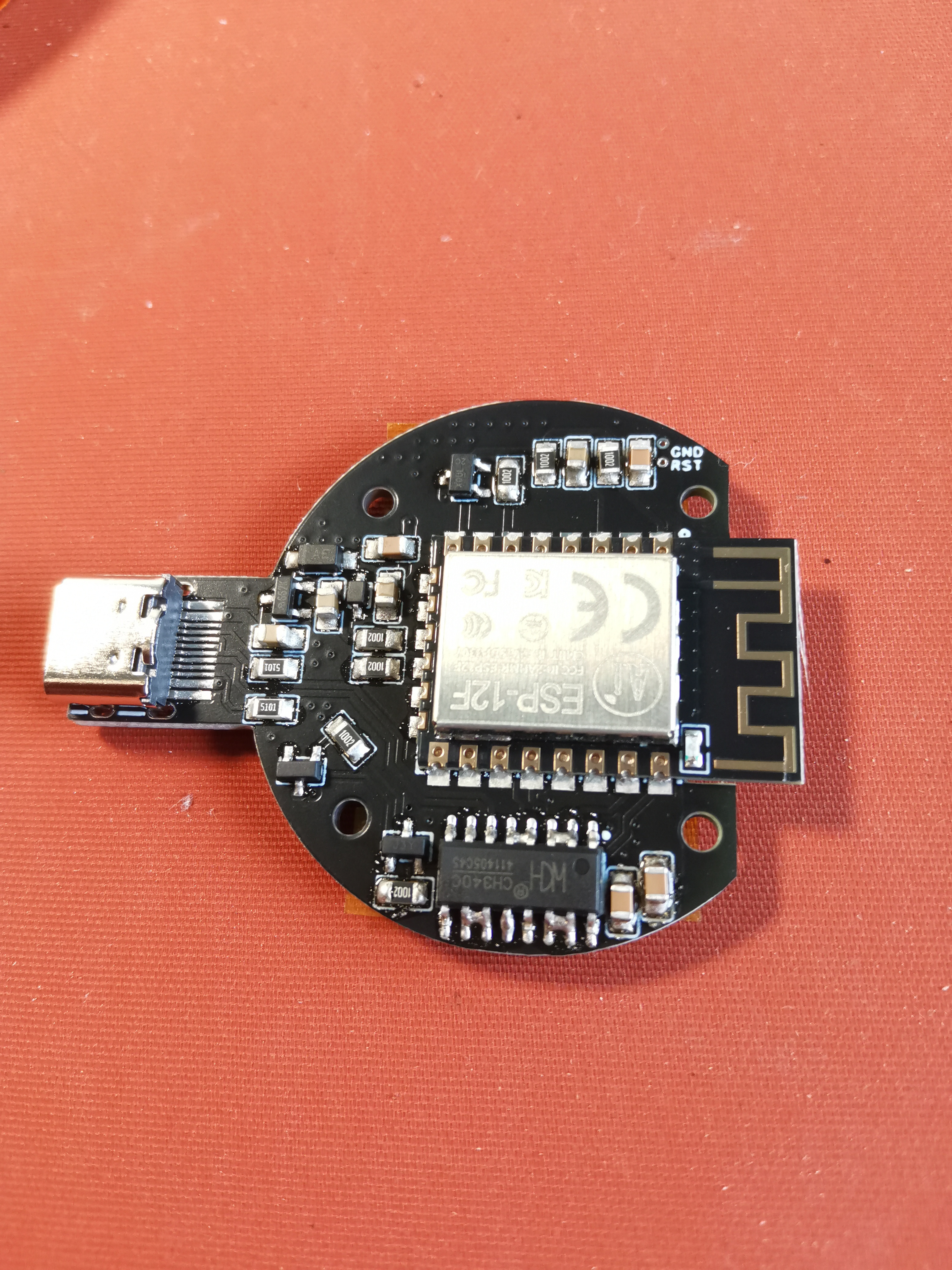
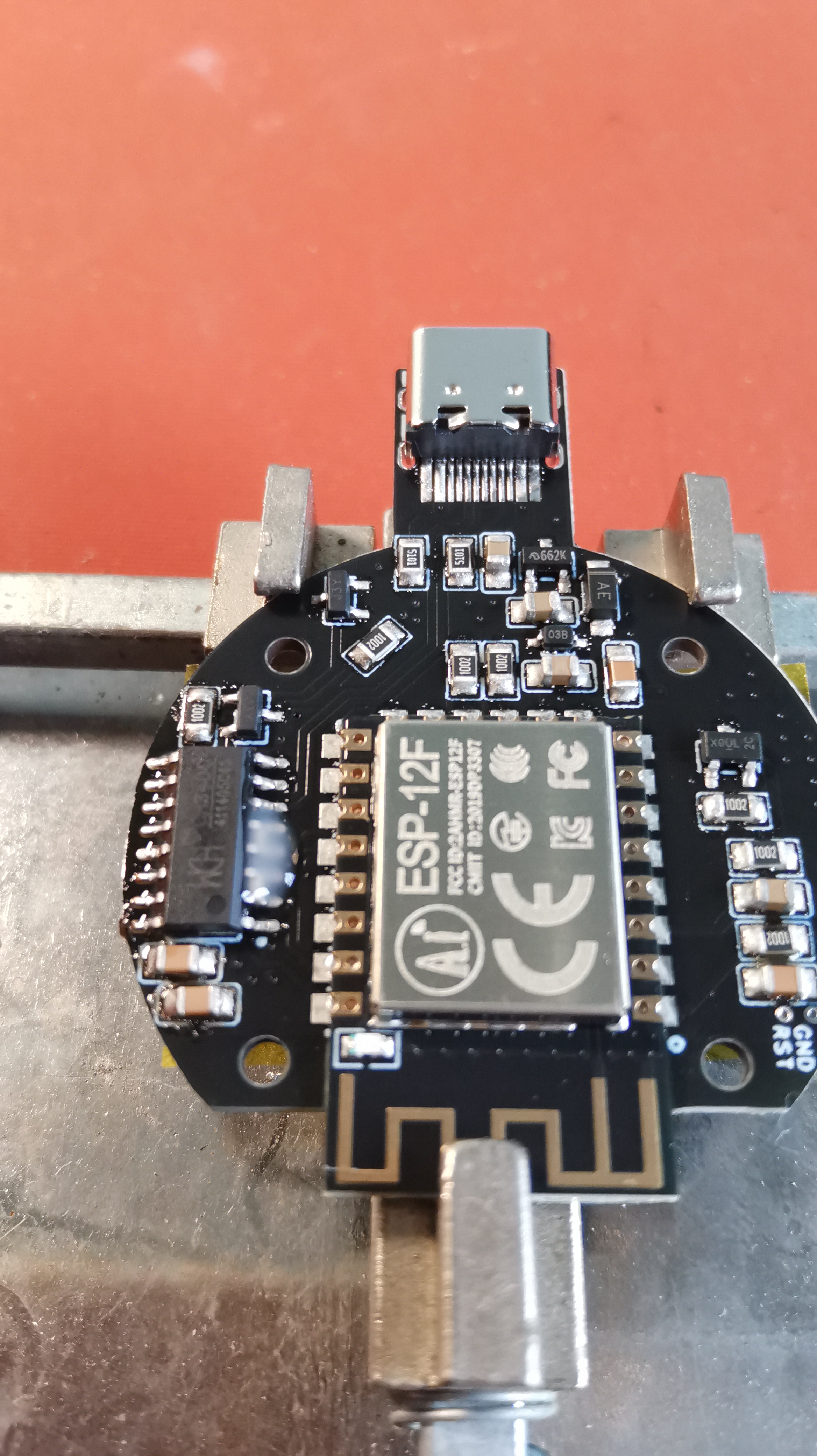
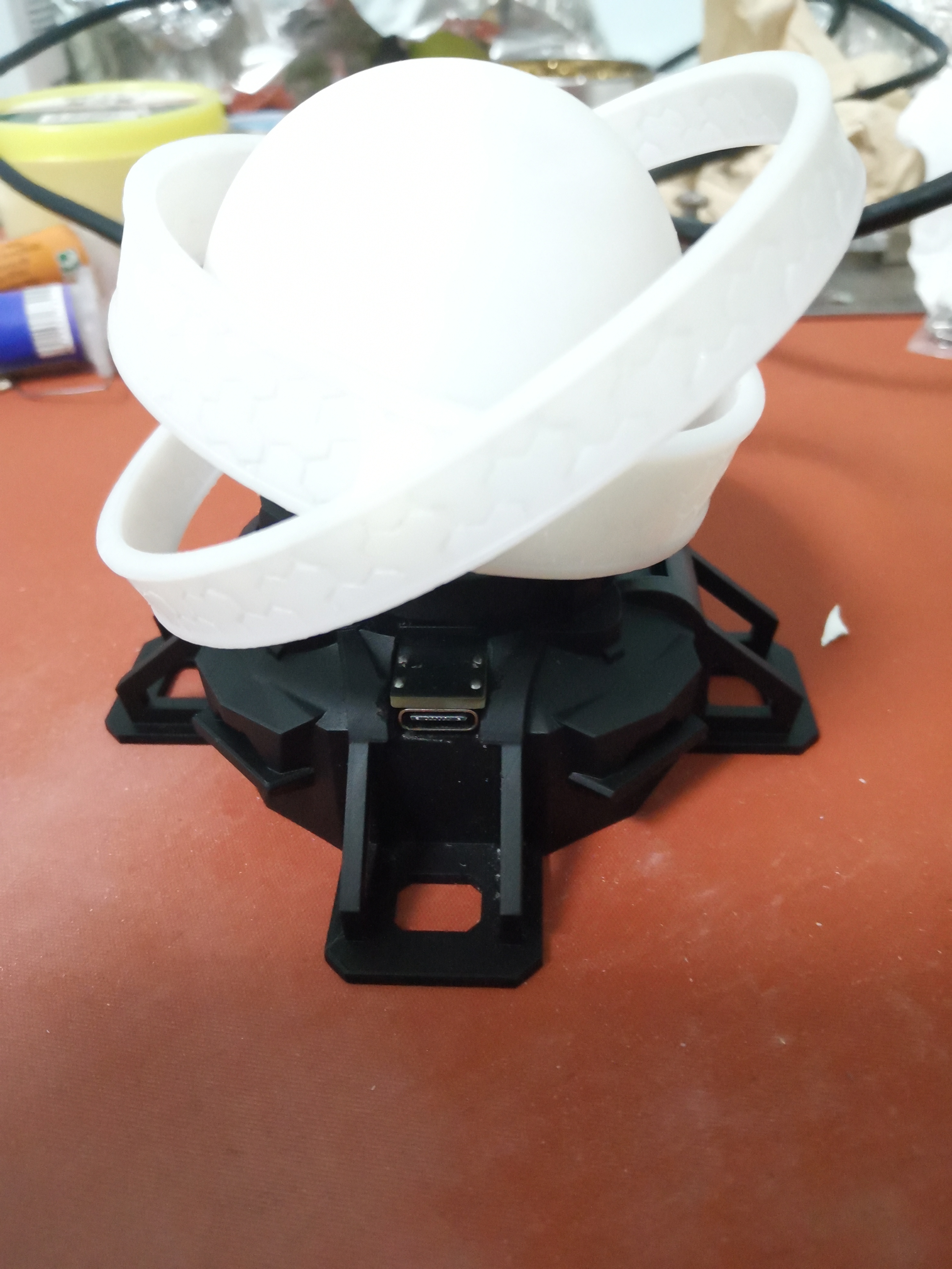
Dyson RGB WiFi LED
This Dyson sphere light was made using ESP8266 and WS2812, and supports WLED or Blinker control.
Demonstration

video:
https://www.bilibili.com/video/BV1r94y1k71H/
Update Log
2022/8/16: Added WLED firmware usage instructions
. Purchase List:
PCB components, 3D printed parts x2, M2 hex nuts x4, M2*7 round head screws x4 (Do not buy self-tapping screws; the thread ends are flat, not pointed. You can find them by searching "M2*7 screws" on Taobao).
Tools & Consumables:
Type-C data cable, tweezers
, screwdriver
, glue (used to fix nuts to 3D printed parts; 502 glue is not recommended as it is not very effective but not unusable), soldering iron, solder wire,
gold finger tape, solder paste (recommended for beginners; it is recommended to buy syringe-type low-temperature solder paste), heat gun (recommended for beginners), flux (recommended for beginners; buy no-clean or BGA soldering fluid; do not buy halogen-containing flux as it will conduct electricity).
PCB Purchase
Download JLCSC Order Assistant: https://www.jlc.com/portal/appDownloadsWithConfig.html
Left-side Coupon Center > Free Coupon Claim > JLCSC EDA Dedicated Coupon for 1-4 Layers (including aluminum substrate) PCB Order > Pricing/Order Placement > Upload Attached Gerber File Board Type: FR-4 Quantity: 5 Thickness: 1.6mm Solder Mask Color: It is recommended to choose a favorite color from green, blue, and black. White is not recommended (only white solder mask bridges have had problems, I don't know if it's an isolated case). In Other Requirements, select Specified Location Add Customer Code. Leave all other options as default or
choose any free shipping option.
On the right, select Coupon, and the price will become free.
Submit the order, then confirm the order and pay (although it's 0 yuan, you still need to click pay).
Component Purchase (Because there is a minimum purchase quantity, you will have many components left after completing one).
Components are recommended to be purchased from LCSC Mall: https://www.szlcsc.com/
Select BOM matching and upload the attached BOM.
Components are recommended to be purchased from Taobao (cheaper):
Reference Shop: Shenzhen Youxin Electronics Technology Co., Ltd. (search for Youxin Electronics directly).
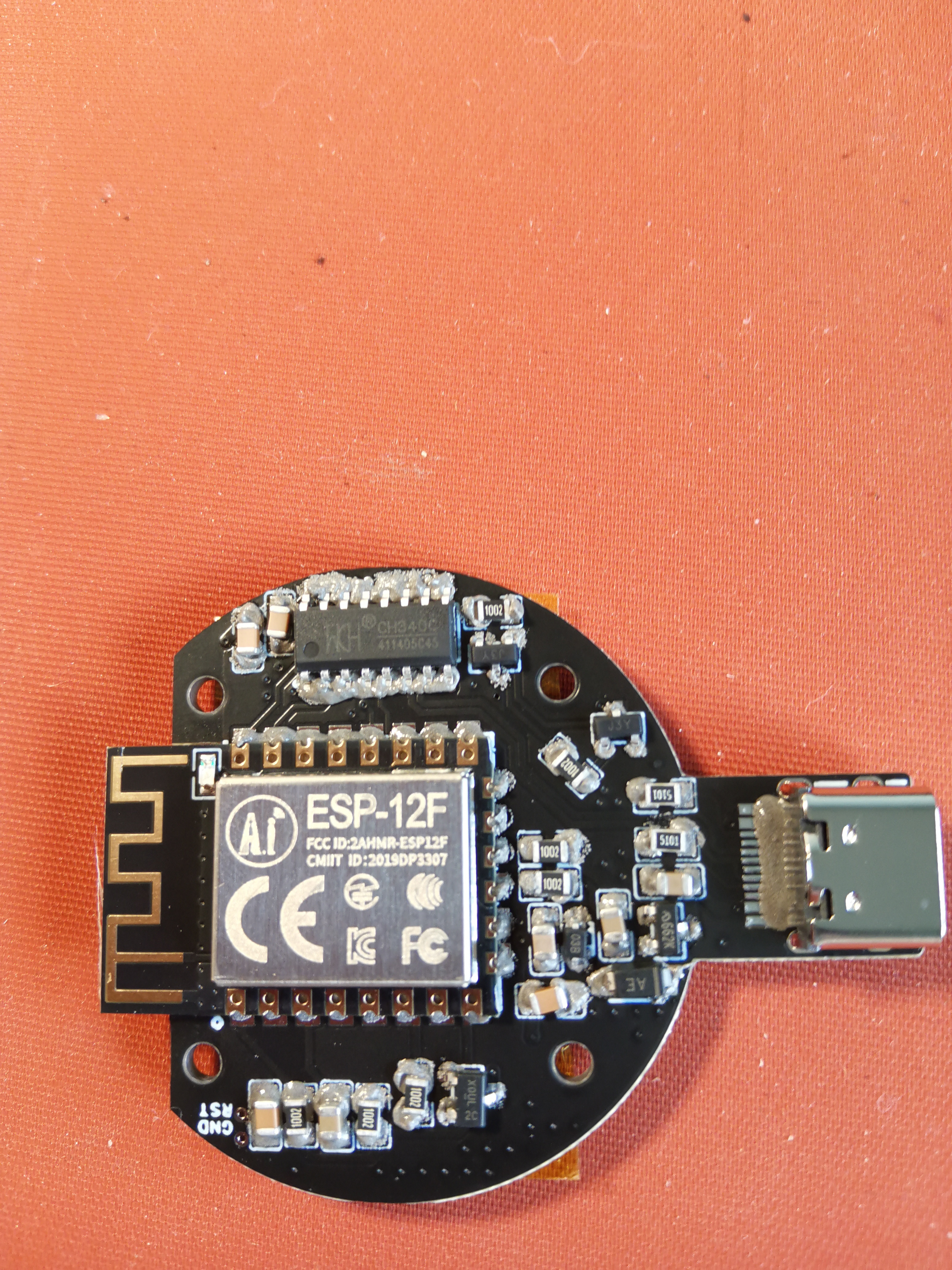
ESP-12F (single set usage: 1)
CH340C (single set usage: 1)
were purchased on Taobao. Simply uncheck or delete the materials and place
the order with one click. For 3D printing ,
open the JLCPCB order assistant
on the left, go to 3D Printing > Enter 3D > Upload the two attached STL files.
Sphere: LEDO 6060. Base: Imagine Black (black base in the demo image) or 8001 (transparent base in the demo image; the resin was randomly selected; I'm not sure if it's semi-transparent, but I think it is). For other preferred
surface treatments, choose coarse grinding. I haven't tried 8001 fully transparent; perhaps spray painting is necessary?
Then submit the order, wait for approval, and make payment. The total price should be less than 60 yuan (excluding postage). All components are 0805 packages.
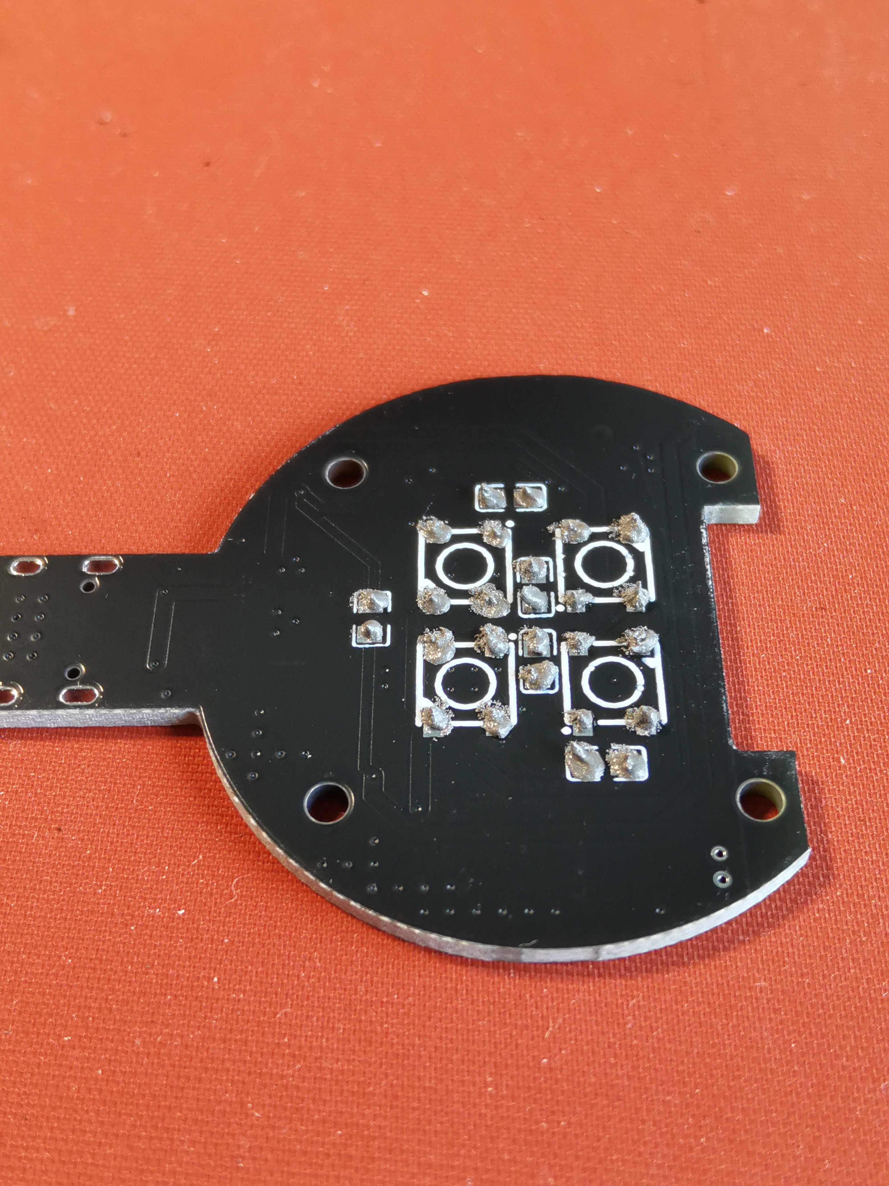
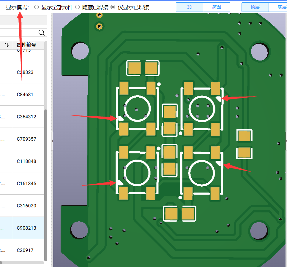
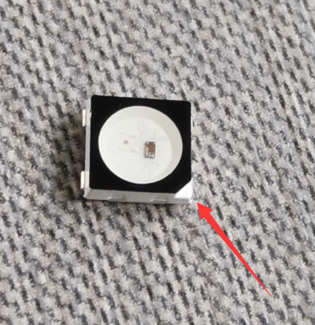
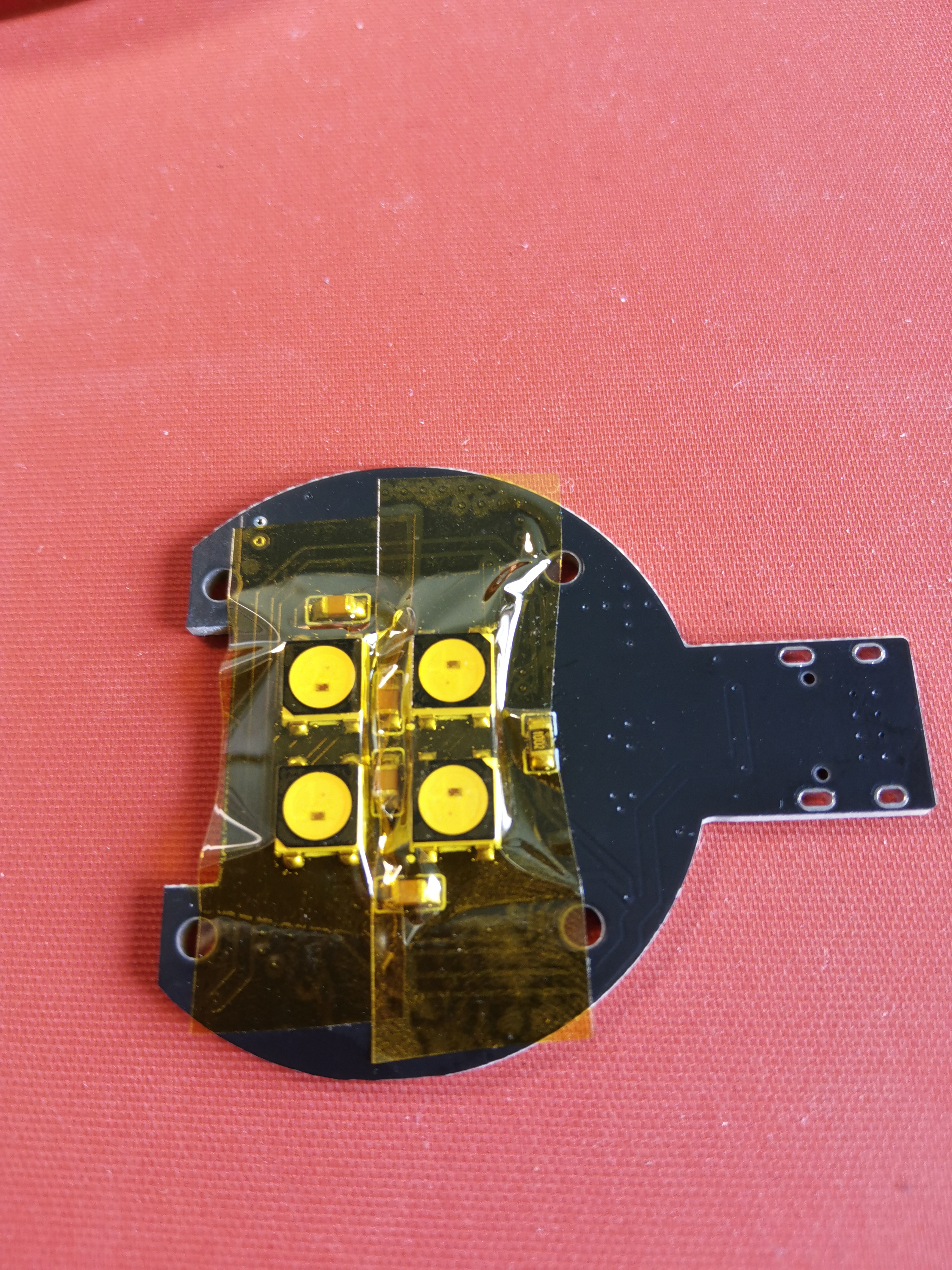
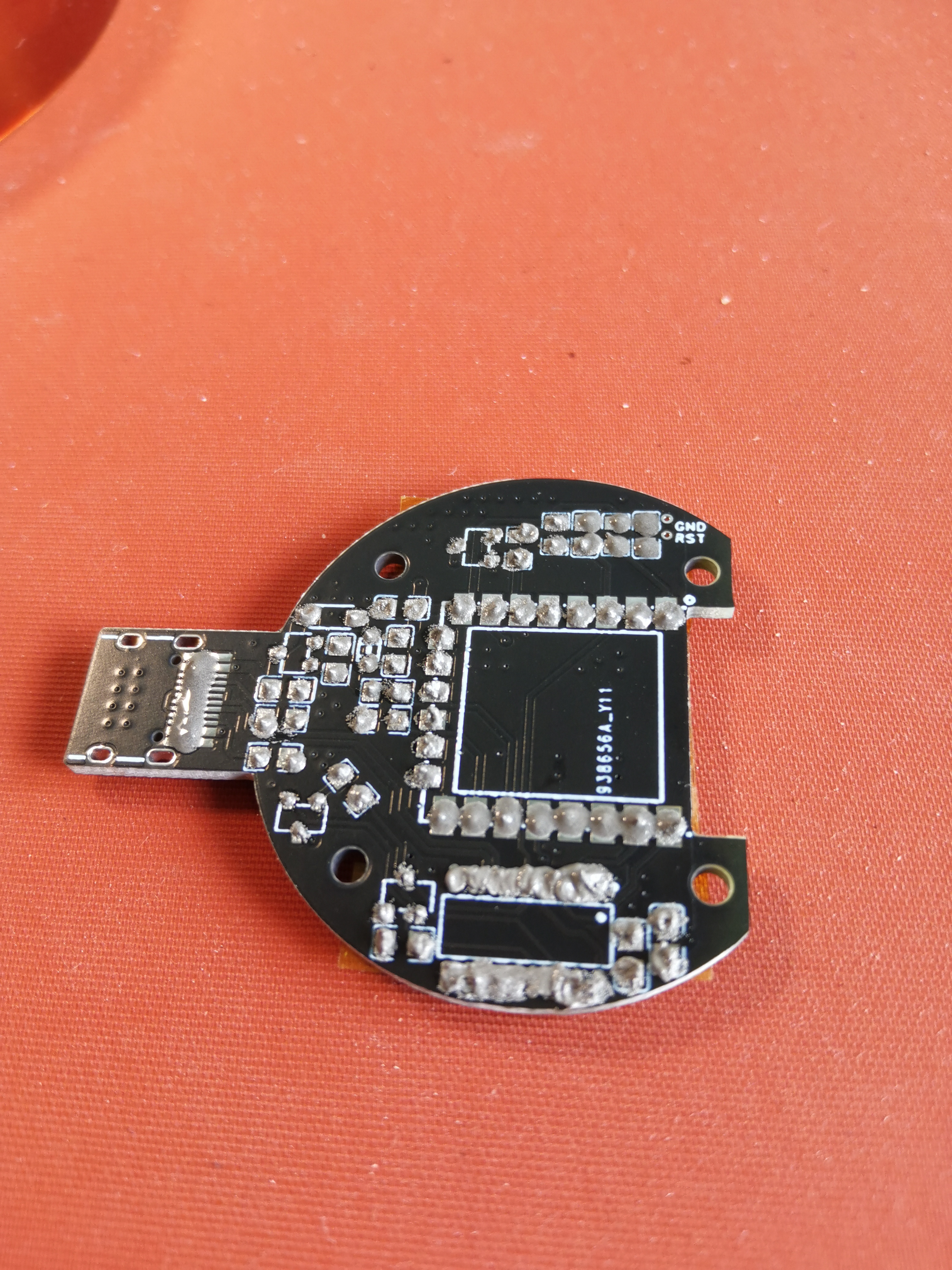
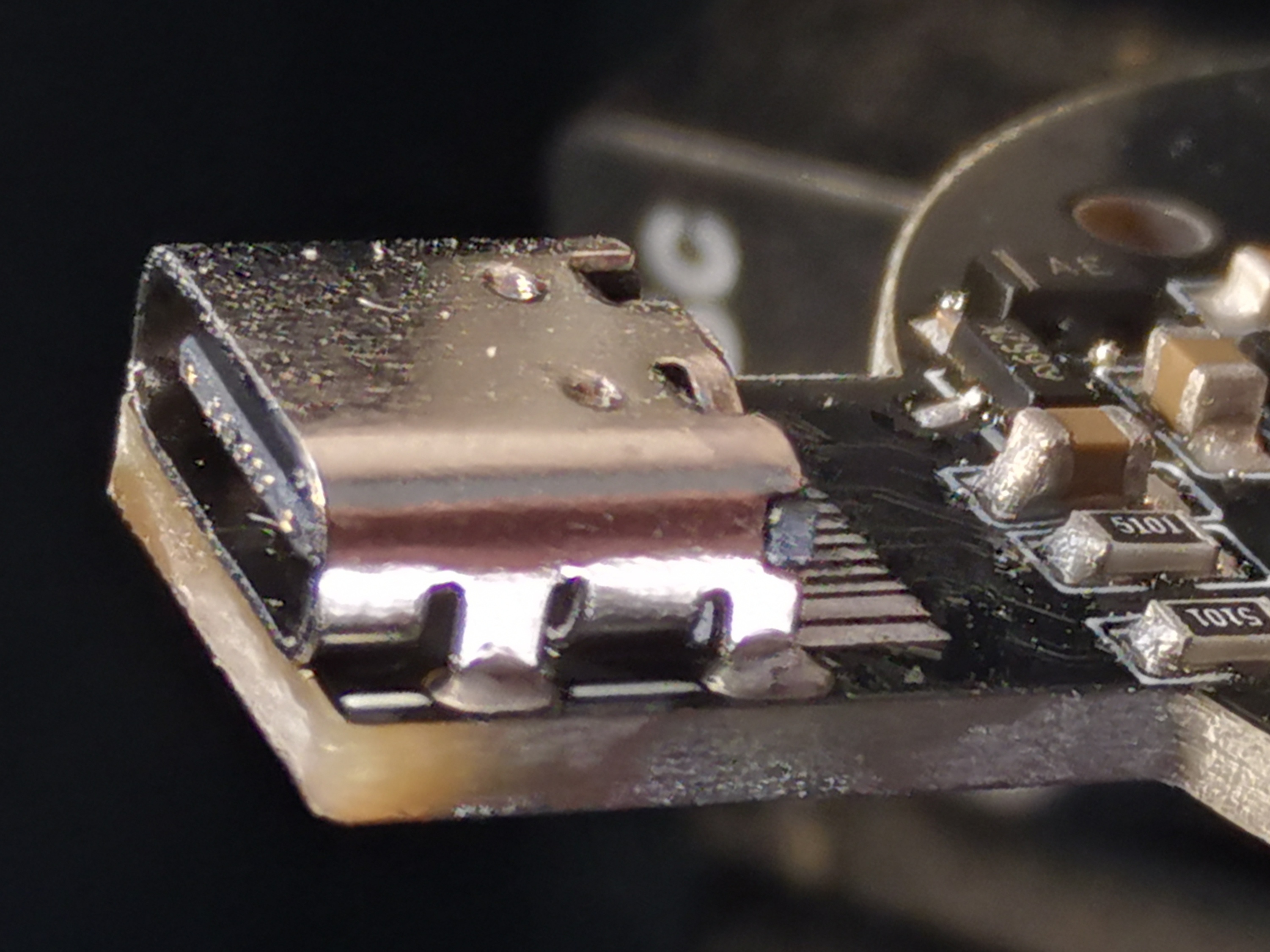
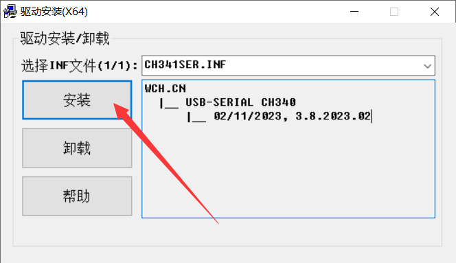
Soldering with a soldering iron isn't difficult , but the component spacing is relatively small. Beginners are advised to use solder paste and a hot air gun. It's recommended to buy low-temperature solder paste in syringes. The following demonstration uses solder paste and a hot air gun, which can be viewed in conjunction with the Bilibili demonstration video: https://www.bilibili.com/video/BV1r94y1k71H/ Apply solder paste to the front (a small amount overflowing is fine; it will shrink after heating). Arrange the components (you can use the attached soldering aid.html, which shows the component model and quantity; you can rotate and click on the components on the right, and click on the left to highlight all components of the same model). Note that some components are directional: WS2812B-B/W (the notched corner on the component corresponds to the small white triangle on the PCB). SMF5.0A (white line on component corresponds to white line on PCB) resistor (black markings side up) CH340C (white dot on component corresponds to white dot on PCB) What to do if the markings on the PCB are obscured by solder paste: Switch the display mode on the soldering assistance webpage to hide components. When placing components on the PCB, it's recommended to start with smaller ones and work up to larger ones. Use tweezers to hold the component onto the pad, gently press it down (a slight tilt is fine), then heat with a hot air gun. For low-temperature solder paste, you can use 250 degrees Celsius. After cooling, use gold finger tape to secure the component to prevent it from falling off when reversing the heat. Apply solder paste to the reverse side. For densely packed pads like Type-C and CH340C, you can apply a single strip of solder paste. Place components (start with smaller ones, then larger ones, paying attention to direction). After heating with the hot air gun , you can see that the CH340C has bridging. If you're lucky with Type-C, there might not be any bridging . How to deal with bridging: Apply flux (it's okay to apply more, it's non-conductive, and overflowing won't cause any problems), then use a soldering iron with a spatula tip to smooth it out (demonstration available in video: https://www.bilibili.com/video/BV1r94) (y1k71H/) If the Type-C connector has bridging, the same procedure applies, but be careful not to let flux flow into the connector. You can use tweezers to hold down the two recesses on the Type-C connector to prevent it from moving, then use a soldering iron with a blade tip to drag it. Do not solder for too long, otherwise you may damage the plastic of the connector. Solder the four mounting pins of the Type-C connector from the front of the board. You can set the soldering iron temperature slightly higher. If you see solder flowing through the solder from the back of the board, it means the solder is secure. Finally, remove the adhesive and check for any other bridging. If you see large solder balls, you can remove them with tweezers; leave the small ones alone. If you have a multimeter, you can check for short circuits between the positive and negative terminals. Burn the program first to test it, in case you find problems after installation. Download and install the CH340 driver: https://www.wch.cn/downloads/CH341SER_EXE.html Download ESP FLASH TOOL: https://docs.ai-thinker.com/esp_download Unzip and run flash_download_tool_X.XXexe. Select firmware 1 as shown in the image : WLED (Recommended, feature-rich) Chinese firmware (Recommended, machine translated, only commonly used functions are translated): Download the attached d1_mini.bin. Official English firmware: https://github.com/Aircoookie/WLED/releases Download WLED_X.X.X_ESP8266.bin


/*****
2: Blinker (features limited)
Download the attached blinker.bin file
*****/
Copy the path and paste it to the arrow position
, e.g., C:\myFolder\XXX.bin.
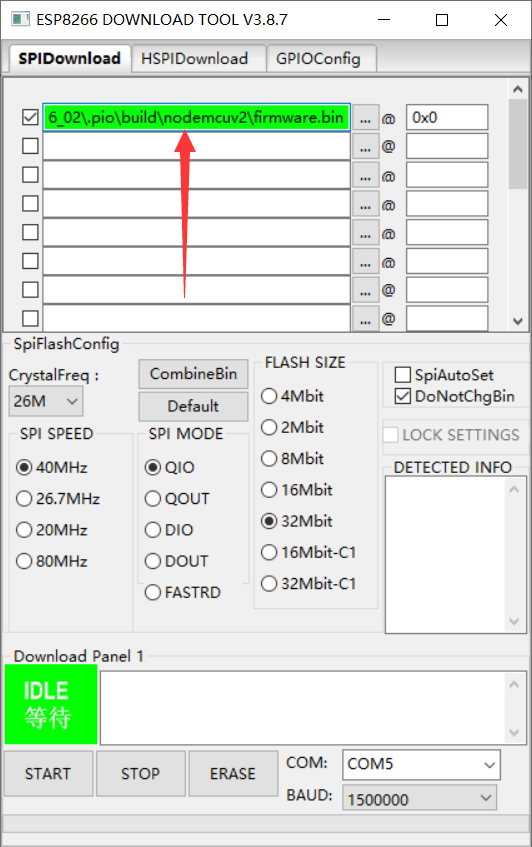
Other settings should follow the image (note that 0x0 is the number 0, not the letter O).

Connect the soldered board to the computer using a data cable,
then select COM (usually there's only one; if there are multiple, check which one appears after insertion).
Select BAUD, set it to maximum. If there's an error, you can reduce the setting.

Click ERASE, wait for completion

, then click start, wait for completion,

and reconnect the board.
WLED firmware:
The appearance of WLED-AP WiFi indicates a high probability of a problem; the orange light should still be on.
/*****
Blinker Firmware:
If the LED light is red, it means there's probably no problem.
*****/
I
'm too tired to do the coloring, so I'll leave it to you guys. Here's
a rendering. When you

receive
the 3D printed parts, there will be some residual liquid (ethyl acetate?). You can wipe it off slightly, then wash it with water and dry it.
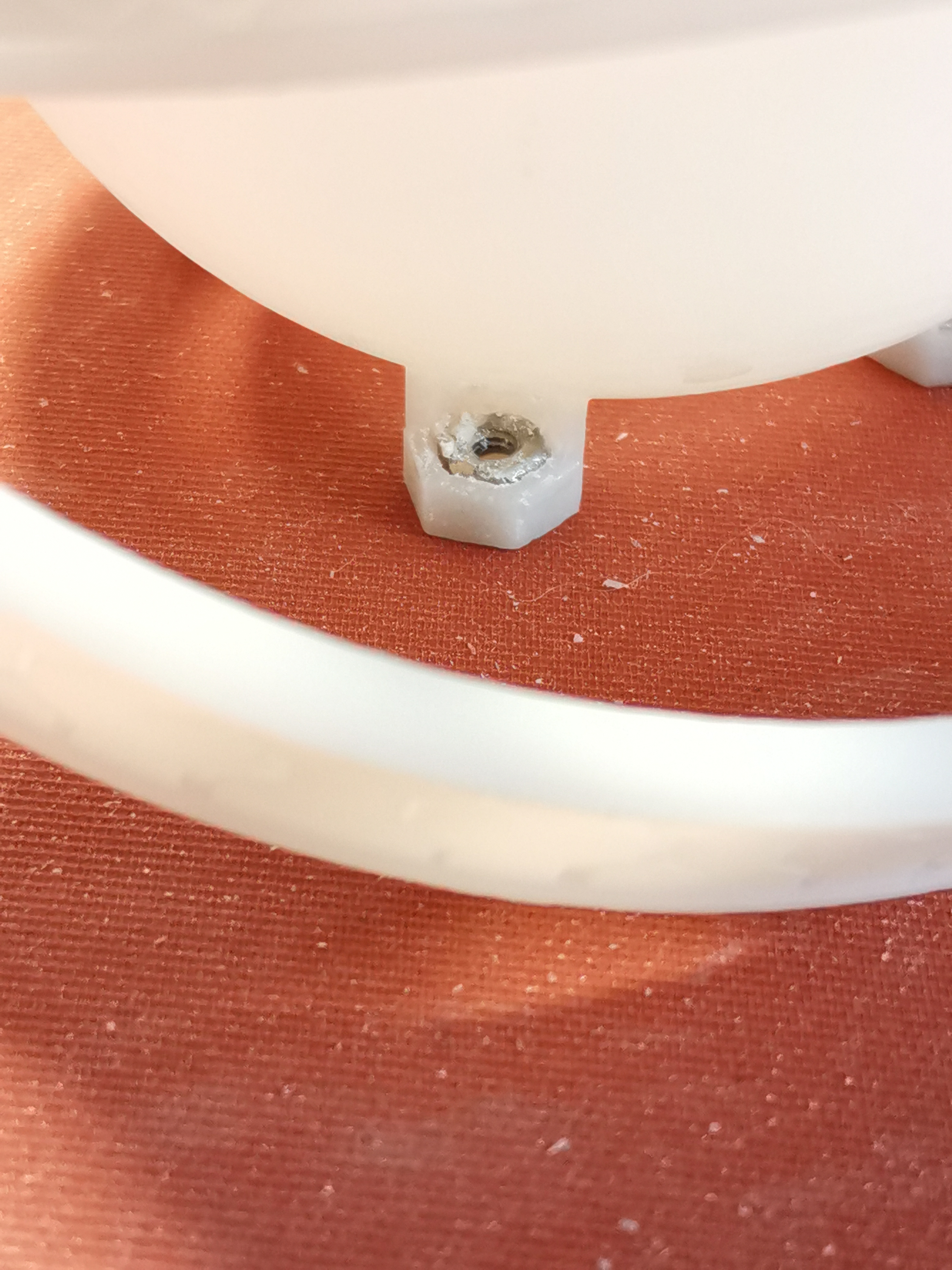
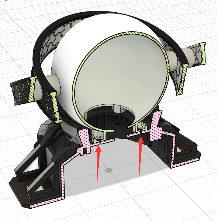
Install the four nuts into the grooves at the bottom of the ball and fix them with glue (I don't recommend 502 glue, the effect isn't very good, but it's not unusable).
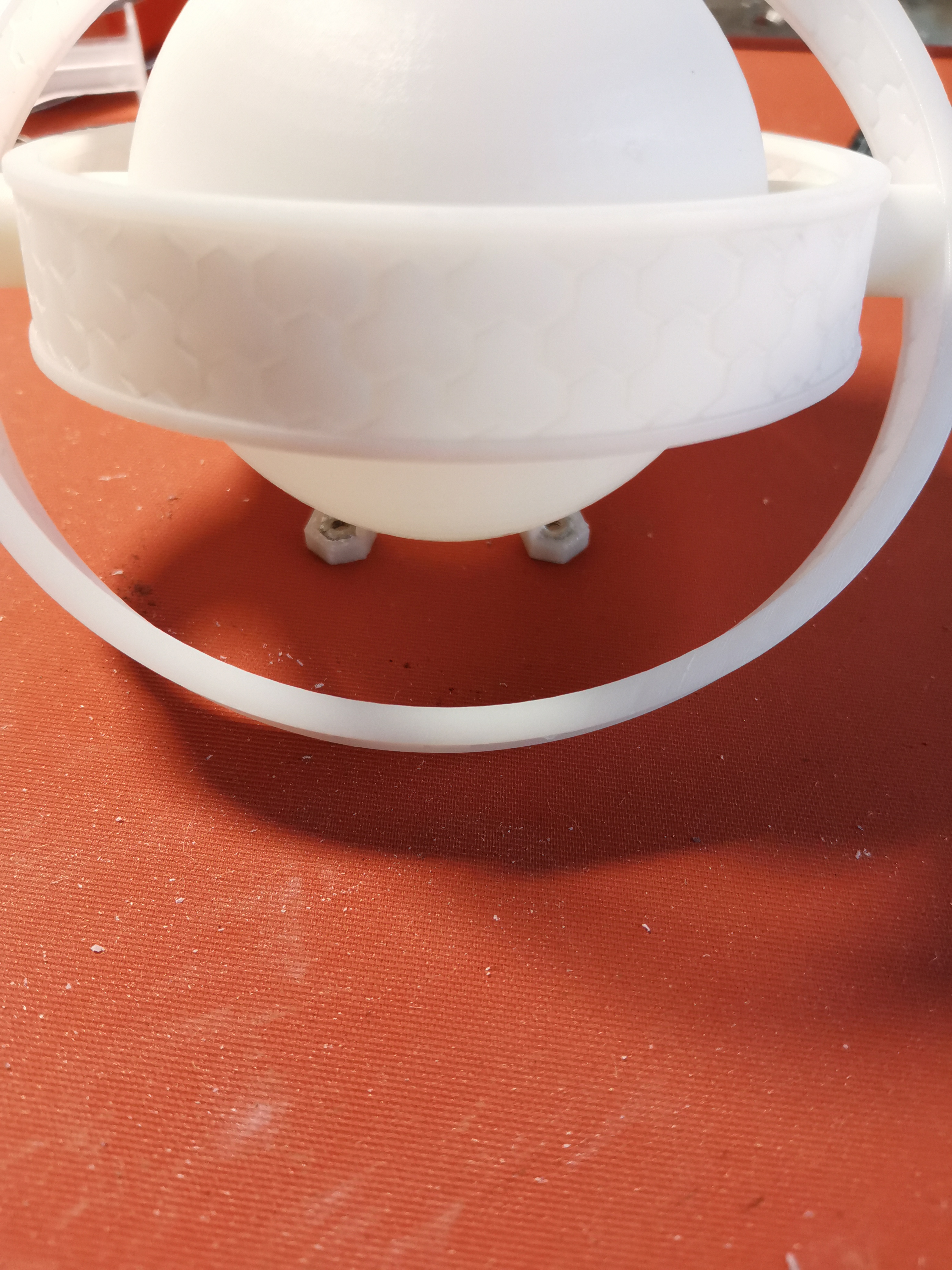
Install the PCB onto the base, making sure not to install it backwards.

Align the four nut holes on the ball, the four holes on the base, and the holes on the PCB, and install the screws.
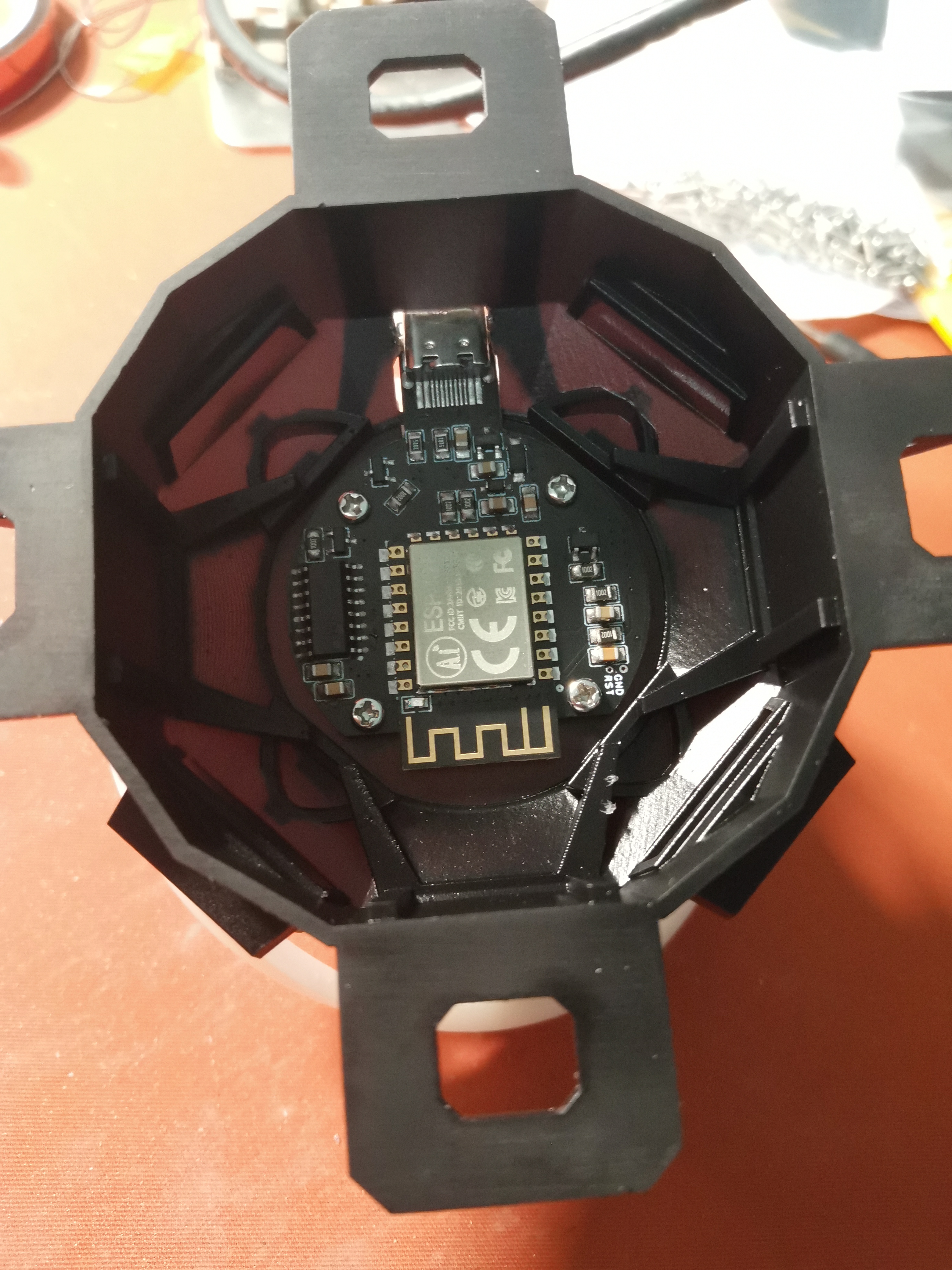
Due to a design issue, the Type-C hole is too small, so I used a utility knife to heat it up and cut a piece. The attached STL file has been enlarged, so it shouldn't need to be cut.
Using
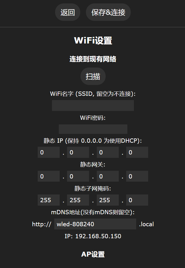
WLED Firmware: After
connecting to the WiFi named WLED-AP
with the password wled1234,
a configuration webpage will automatically appear.
Enter WiFi Settings
and click Scan. In the Network name field, select your WiFi (only 2.4G can be selected, and only 2.4G WiFi can be scanned).
Enter the WiFi password. (Password)
Then save (Save & Connect)
and download the WLED app:
Github: https://github.com/Aircoookie/WLED-App/releases
Google Play: https://play.google.com/store/apps/details?id=com.aircoookie.WLED&pcampaignid=MKT-Other-global-all-co-prtnr-py-PartBadge-Mar2515-1
App Store: https://apps.apple.com/us/app/wled/id1475695033
Considering some people don't know how to access Github, you can directly download the attached APK file
or directly enter the ESP8266's LAN IP address (which can be found on the router's management page, named wled-WLED).
In the app, click the plus sign in the upper right corner (skip this step if accessing directly via IP).
Click DISCOVER LIGHTS...
and it will display "Found WLED!" Afterwards, click
the WLED icon to enter the usage page.
Click the settings (Config) in the upper right corner (skip this step if using Chinese firmware)
to enter LED Preferences.
Change the Length to 4 and GPIO to 13 in Hardware setup.
Change Button 0 GPIO to Unused or -1 and Disabled.
Change Relay GPIO to 12 and check Invert.
Then save. Return to the color palette page and
click the Power icon in the upper left corner twice to ensure Power is in the high-brightness state .
Then click the color palette to display colors normally.

Basic usage:
The sun slider at the top can be used to adjust the brightness.
The Effects at the bottom can switch effects. Solid is the default display mode.
After selecting an effect, you can slide down the Color page at the bottom to select the color of the effect.
Colors and effects are used together. Try a few and you'll understand.
The slider at the bottom of the Effects page can adjust the speed and intensity of the effect
.
Blinker Firmware:
Download and register Blinker: https://diandeng.tech/dev
Add Device > Standalone Device > Network Access
Then click New Device > the three dots in the upper right corner >
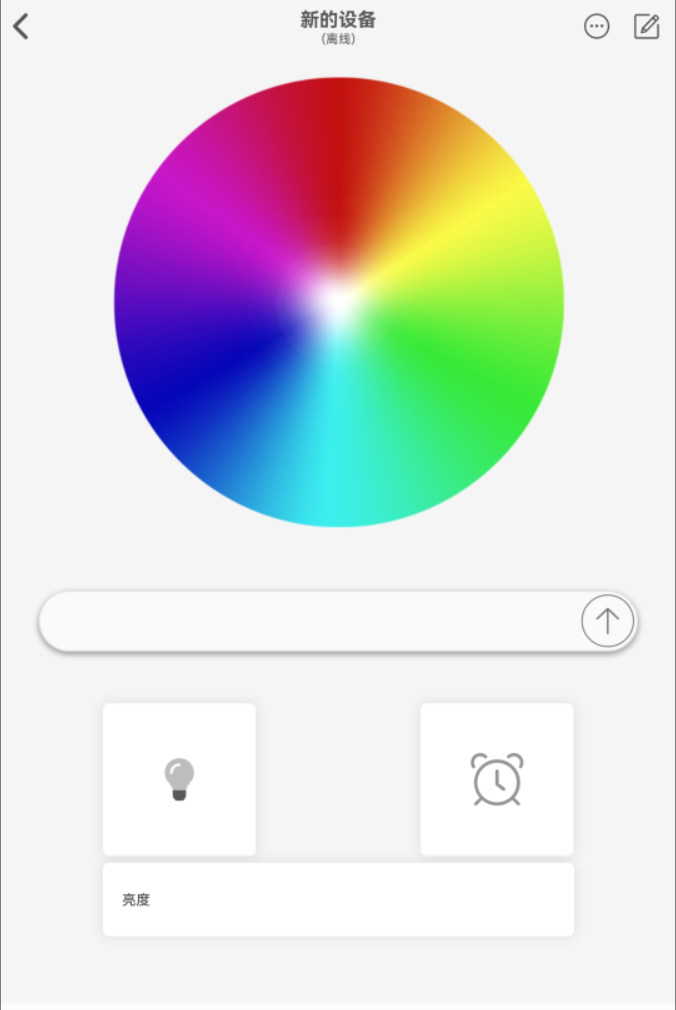
Delete all Interface Configuration, then paste the following content (if you have any problems, you can download the attached txt file, which contains the same content):
{¨version¨¨2.0.0¨¨config¨{¨headerColor¨¨transparent¨¨headerStyle¨¨light¨¨background¨{¨img¨´´}}¨dashboard¨|{¨type¨¨btn¨¨ico¨¨fad fa-lightbulb¨¨mode¨Ê¨t0¨´´¨t1¨¨text2¨¨bg¨É¨cols¨Ë¨rows¨Ë¨key¨¨switch¨´x´Ê´y´Ñ¨lstyle¨É¨clr¨¨#595959¨}{ßA¨tim¨ßIÉßJËßKËßL¨timing¨´x´Î´y´Ñ}{ßA¨col¨ßF´´ßO¨#389BEE¨ßIËßJÏßKÏßL¨color¨´x´ Ê´y´ÉßNË}{ßA¨ran¨ßF¨brightness¨ßOßT¨max¨¢1c¨min¨ÉßIÉßJÏßKÊßL¨luminance¨´x´Ê´y´¤AßNÎ}{ßA¨inp¨ßIËßJÑßKËßL¨inp-g0y¨´x´É´y´Ï}÷¨actions¨|¦¨cmd¨¦ßM‡¨text¨‡¨on¨¨turn off¨¨turn on¨—÷¨triggers¨|÷¨rt¨|÷}
Update the configuration and restart the software. You should see the components now.
Click the three dots in the upper right corner, copy the key
, and power on the board. A red light will illuminate after power-on, indicating network configuration is enabled.
Connect your phone or computer to the ESP8266 and configure the network using the DSP_Light Wi-Fi. This
will automatically open the network configuration page.

Enter the Wi-Fi name (only 2.4G Wi-Fi is supported), Wi-Fi password, and the Blinker key, then save.
If the Wi-Fi connection is successful, the light will flash yellow, indicating it's connecting to the Blinker MQTT server.
Once the light turns solid yellow, you can control
the color palette, on/off state, timer, and brightness within Blinker. These are straightforward; try them out yourself.
Text input box usage:
Send hexadecimal color (requires a hash symbol, case-insensitive): #ff00ff
Send RGB color (requires parentheses): (255,0,255)
*****/
Other issues:
This project is prohibited from sale
/*****
Blinker Firmware:
How to reconfigure the network/how to change the key or Wi-Fi/what to do if the key is entered incorrectly:
Method 1: Turn off the router; if unable to connect to Wi-Fi, it will automatically reconfigure the network.
Method 2: Short-circuit GPIO2 and GND with tweezers until the light turns red (this should take about ten seconds).
Method 3: Re-flash the firmware
. Red light/unable to connect to Wi-Fi:
Can only connect to 2.4G Wi-Fi; try again closer to the router.
Flashing yellow light:
Check if the network is working properly.
Yellow light constantly on but showing offline:
The device and the light need to be on the same local area network; check if the router is blocking communication between devices
.
Welding Assistance.html
BOM_oshwhub_dsp_01_v1.xlsx
Interface Configuration.txt
gerber_oshwhub_dsp01_v1.zip
Base_oshwhub_v2.stl
ball_oshwhub_v2.stl
blinker.bin
d1_mini.bin
WLED_1.1.0.apk
PDF_Dyson RGB WiFi Light Sphere.zip
Altium_Dyson RGB WiFi LED Sphere.zip
PADS_Dyson RGB WiFi LED Sphere.zip
BOM_Dyson RGB WiFi LED.xlsx
90789
electronic


 京公网安备 11010802033920号

 114195-50-23-101/003


