August 29, 2024 Update:
I haven't logged in for a long time for some reasons, and I apologize. I found that all my previous comments are gone, and I can't comment under the project anymore; submitting results in an error. This seems to be a bug in the LCSC system, and I'm not sure why LCSC hasn't fixed it. I've also tried re-editing the project, but I still can't comment. I've received many private messages in the backend, all inquiring about the project or requesting modified source code. There are simply too many to reply to individually. I see that Qifan has now released the source code, so that everyone can improve it themselves. Therefore, I'm also releasing my modified source code here. Additionally, I completely redesigned the heating platform's outer shell, modeled after the one from the "Find Sheep" design. It's still compatible with the "Find Sheep" shell; only minor modifications were made. If you've already printed the "Find Sheep" version, you don't need to print it again. I modified the screw holes for easier installation, removed the test button, and made adaptations for FDM printing, along with other minor optimizations. This was primarily a remake for learning Fusion 360. There are two versions of the upper shell; you only need to print one. One version is optimized for FDM and can be printed directly without a support. I hope this is helpful. The relevant files are attached; please download them yourself.
Shell 3D printing files: 3D printing files (if the link is broken, it may be under review).
This project originated from the LCSC community; thank you to the original authors for their hard work!
Heating platform mass production plan: https://oshwhub.com/sheep_finder/pcb-heng-wen-jia-re-tai
Qifan Technology's IoT heating platform: https://oshwhub.com/dhx233/pcb-heng-wen-jia-re-tai
August 25, 2023 Update:
The original version had a certain probability of automatically heating upon startup. Investigation revealed that the original IO14 pin (PWM) lacked a pull-down switch; leaving the pin floating during startup caused a certain probability of automatic heating (100% occurrence during firmware upload). A 10K pull-down correction was added.
Minor firmware changes: If the fan is manually started when not heating, it must also be manually turned off; a fan icon was added to the display when the fan is running.
Some modifications were made based on the original version. If you haven't seen the original version, it's recommended to review the relevant documentation first; it's very detailed and excellent!
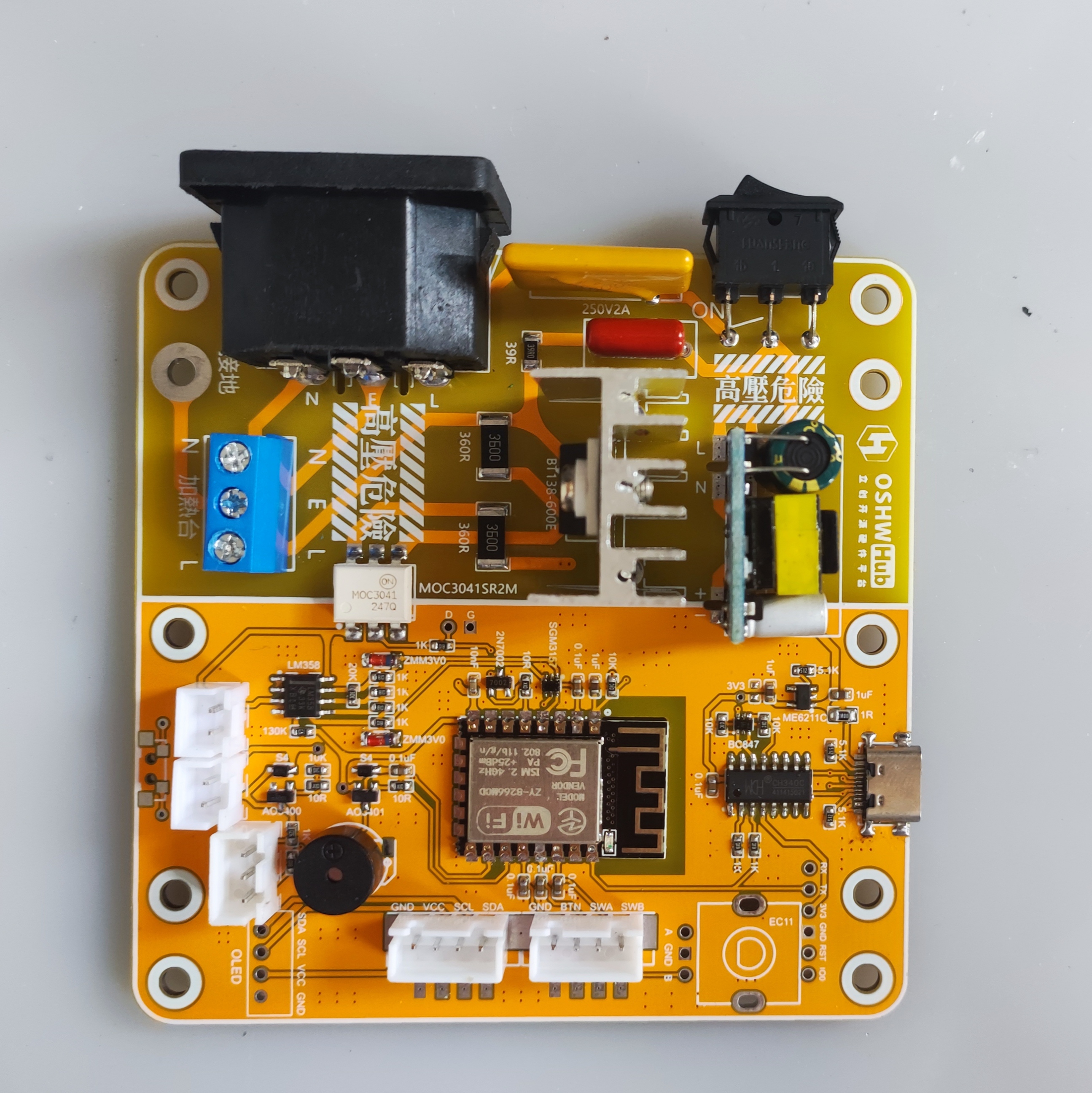
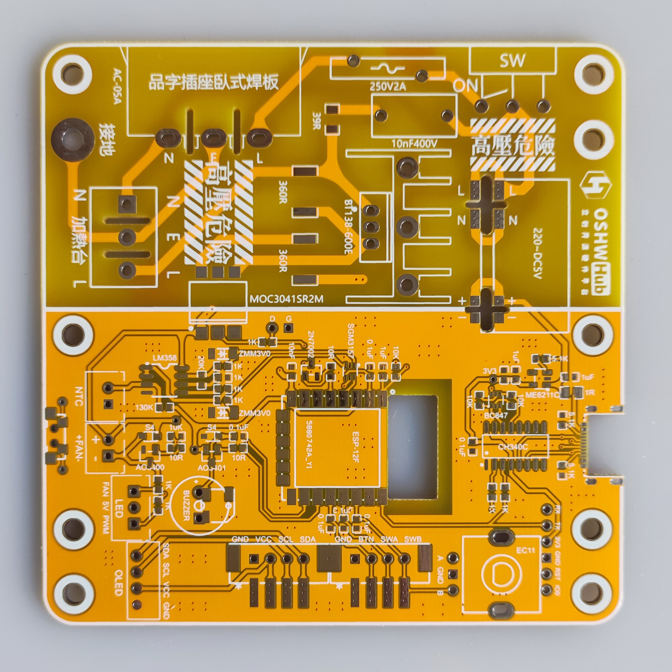
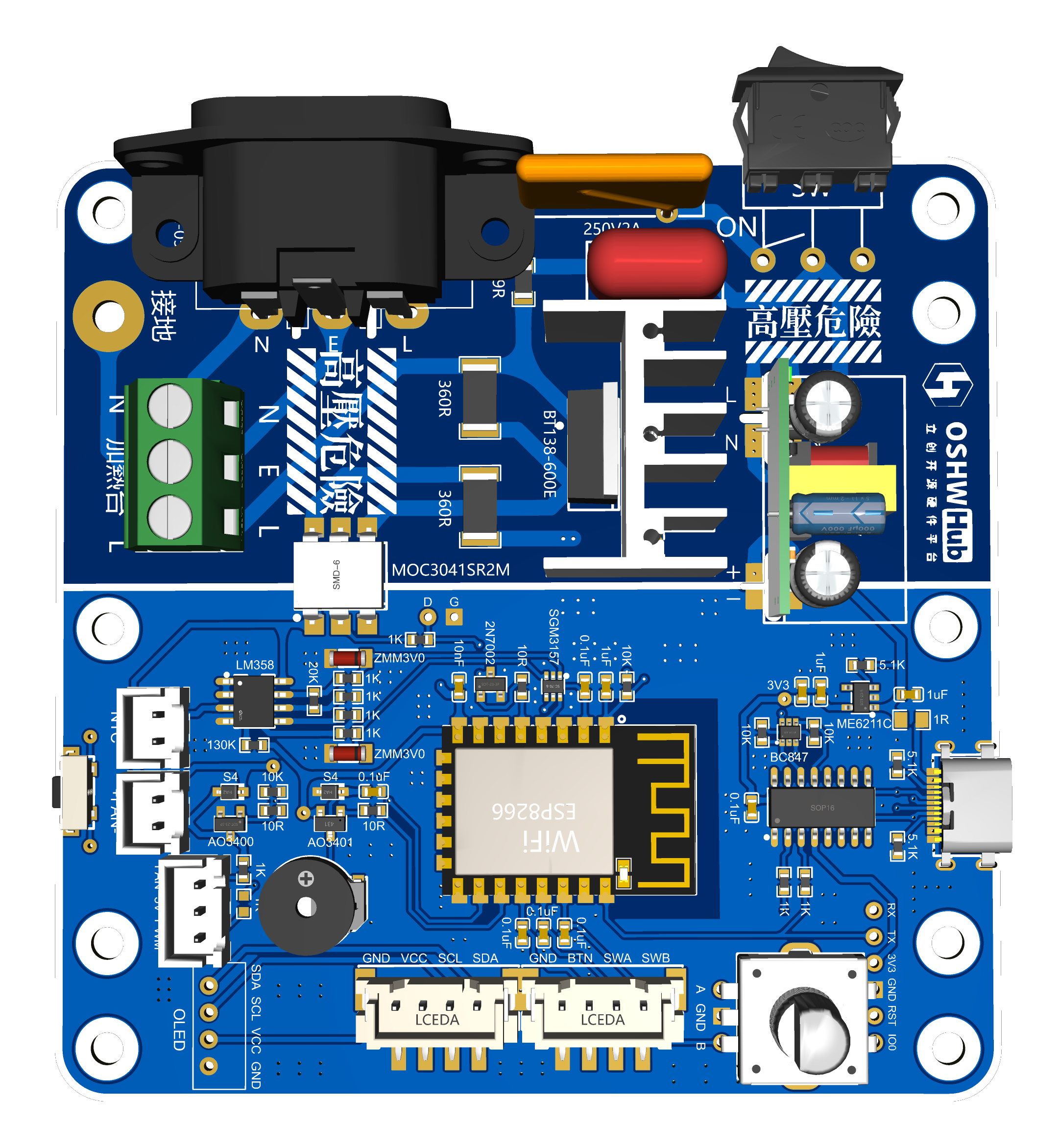
PCB Part - Motherboard:
The motherboard's AC power section remained unchanged; only the low-voltage section was modified.
Both CC pins of the Type-C port have been fitted with 5.1K resistors to ensure compatibility with fast charging cables (the original had the two CC pins shorted, which caused issues with Type-C cables with chips). The resistor and capacitor
packages are now standardized to 0603.
The antenna section of the ESP-8266 main controller has been recessed, theoretically resulting in a stronger Wi-Fi signal.
The original screen and encoder were difficult to plug in, so they have been modified to be compatible with standard XH2.54 straight-through and right-angle connectors, and also compatible with the original.
The original fan microswitch button was not very useful, so a side button with a different package was used (the circuit is disconnected, so soldering is not required, and it is slightly misaligned with the outer casing button).
The original SGM2028 LDO chip has been replaced with ME6211C33M5G-N (C7 10uF is optional), which is also compatible with the original SGM2028, RT9013-33GB, etc., and the circuitry is basically the same; I just prefer using the ME6211C.
Pull-down resistors R28 (IO12-SDA) and R29 (IO13-SCL) have been added (these two resistors are added later and do not need to be soldered). A
10K pull-down resistor has been added to pin IO14 to correct a potential issue of automatic heating upon power-on.
The original fan LED indicator has been replaced with a dual-color LED: green for fan operation and red for heating (which will flash according to the heating PWM status).
A buzzer has been added to provide beeping indications for power-on, heating start, and heating stop.
The original LM358P op-amp pinout has been changed to a surface-mount package, model LM358DR.
Due to modifications to several I/O ports, it is incompatible with the original firmware, but it will normally be updated synchronously with the original firmware.
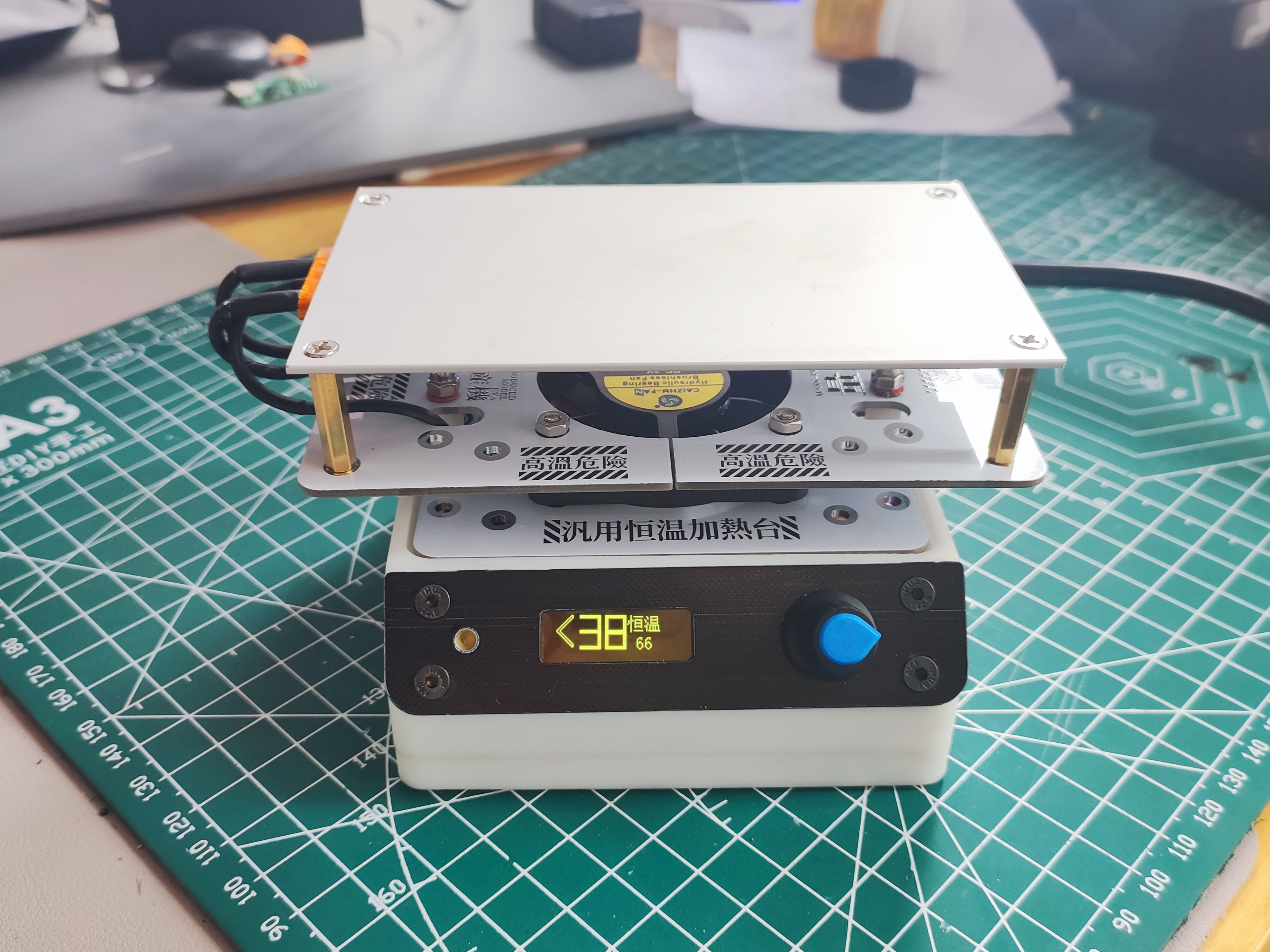
PCB section - middle and upper heat insulation boards:
the two middle holes (two of which connect to the base plate) have had their original pads replaced with slots without metal connections to reduce heat transfer to the motherboard. The upper heating plate's hole positions are based on the Deer Fairy 400W heating plate (70*120mm), but have been changed to an oblong shape to ensure compatibility with other boards on the market that have the same dimensions but slightly different hole positions.
A new PCB for the display cover has been added .
The original project includes a BOM with a purchase link; the link for replacement is:
Replace the original LM358P with LM358DR. Uxin
has added a passive buzzer, compatible with both through-hole and surface-mount types. The through-hole size is 9*4mm (4.2mm is also acceptable), and the surface-mount size is 5*5mm (5020).
A PMOS AO3401 has been added to the buzzer circuit (note that this is AO3401, not AO3400; be careful to distinguish it from the fan circuit during soldering). Uxin
has replaced the original fan LED with a 3mm dual-color LED common anode (color can be chosen according to personal preference). Uxin
has replaced the original SGM2028 with ME6211C33M5G-N (optional). Uxin
has replaced the original 1N4148 diode with a smaller packaged 1N5819WS (S4).
The XH2.54 sockets used in the Uxin display, encoder, fan, and NTC have all been changed to through-hole type (compatible with the original surface-mount type). A new 3P socket for dual-color LEDs has been added. Uxin (this link includes 2P, 3P, and 4P)
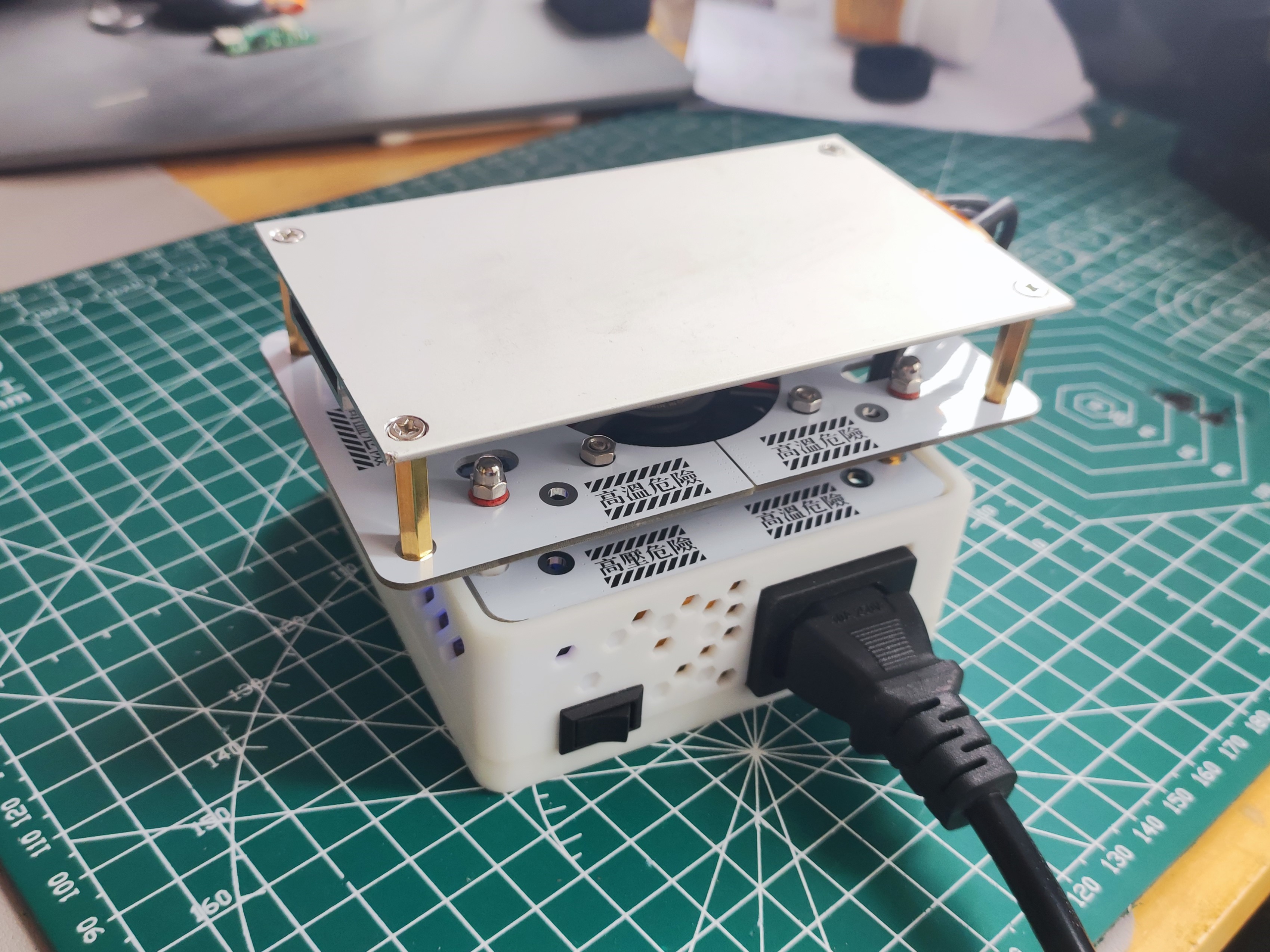
has also made these changes compatible with the original casing
. Firmware modifications:
Based on changes in the hardware IO pins, the relevant IO definitions have been modified
for power-on start, heating start, and buzzer reminders on shutdown. The fan now
requires manual shutdown when manually started at room temperature.
A fan activity icon has been added.
Other minor optimizations are also
included. The revised firmware is in the attachment. To obtain the modified source code, please obtain permission from the original author (Qifan Kechuang) before the source code can be provided (the actual changes in the revised source code are minimal).
For more information, please refer to the original project's

display cover.


 京公网安备 11010802033920号

 EB71F62E28BV2-20.000M


