 , a high-performance, low-cost 32-bit microcontroller from STC Microelectronics. It boasts powerful performance, featuring a 32-bit ARM Cortex-M3 core with a clock speed of up to 72MHz, providing strong processing and computing capabilities suitable for handling complex algorithms and tasks. It offers rich peripheral interfaces, supporting multiple general-purpose timers, multi-channel ADCs and DACs, and abundant communication interfaces such as UART, SPI, and I2C, meeting the needs of various applications. Its low-power design employs advanced low-power design and technology, demonstrating excellent energy efficiency, making it ideal for applications requiring long-term operation or battery power. The device boasts ample storage space, featuring large-capacity Flash memory and SRAM, facilitating the storage of substantial amounts of program code and data. The
  This method is also known as cold start mode. During a cold start, the internal components of the device operate at a lower temperature than during normal operation. High temperatures accelerate component aging and damage; therefore, cold starts help extend the lifespan of electronic components. Furthermore, cold starts reduce electromagnetic interference. The circuit exhibits higher stability during cold starts, with smoother current and voltage changes, which helps reduce electromagnetic interference generated during startup and improves the device's anti-interference capabilities. To improve system reliability, cold starts allow for more precise current and voltage control of devices during the initial operation phase, reducing the risk of damage caused by voltage transients and current surges during startup, thereby improving the overall system reliability and stability. Therefore, circuit cold starts offer significant advantages in energy efficiency, component lifespan, electromagnetic compatibility, and system reliability, making them a commonly used startup method in many electronic devices and system designs.
  uses a 16-pin TYPE-C port, supporting the USB 3.0 protocol for easy data transfer and download. The USB-to-
  Considering the small size of this core board, the CH340N is used as the USB-to-serial chip in this circuit. The IN5819WS chip in the circuit primarily protects the computer hardware, preventing backflow and damage when the USB is plugged into the computer.
  the interactive button circuit
 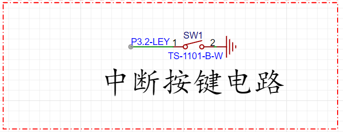 , since serial port code download is used, the STC USB-HID communication protocol is not used. Therefore, the interrupt button on the P32 microcontroller in this computer design functions as a regular button; when the P32 detects a falling edge, it triggers an interrupt and executes the interrupt instruction.
 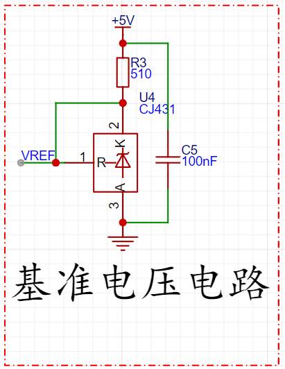 The key operating principle of the TL431 is as follows:
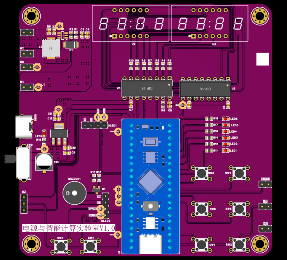
  (PCB image
 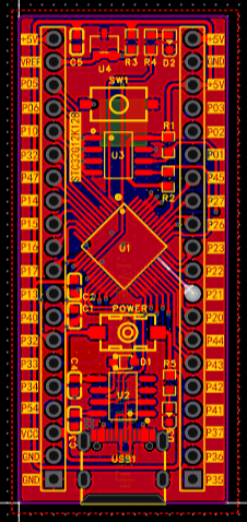 , 3D image,
 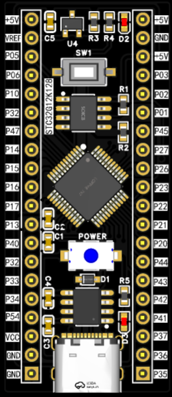 physical sample shown ) I also built an STC32G12K128 expansion board to verify if the core board's functions were implemented.
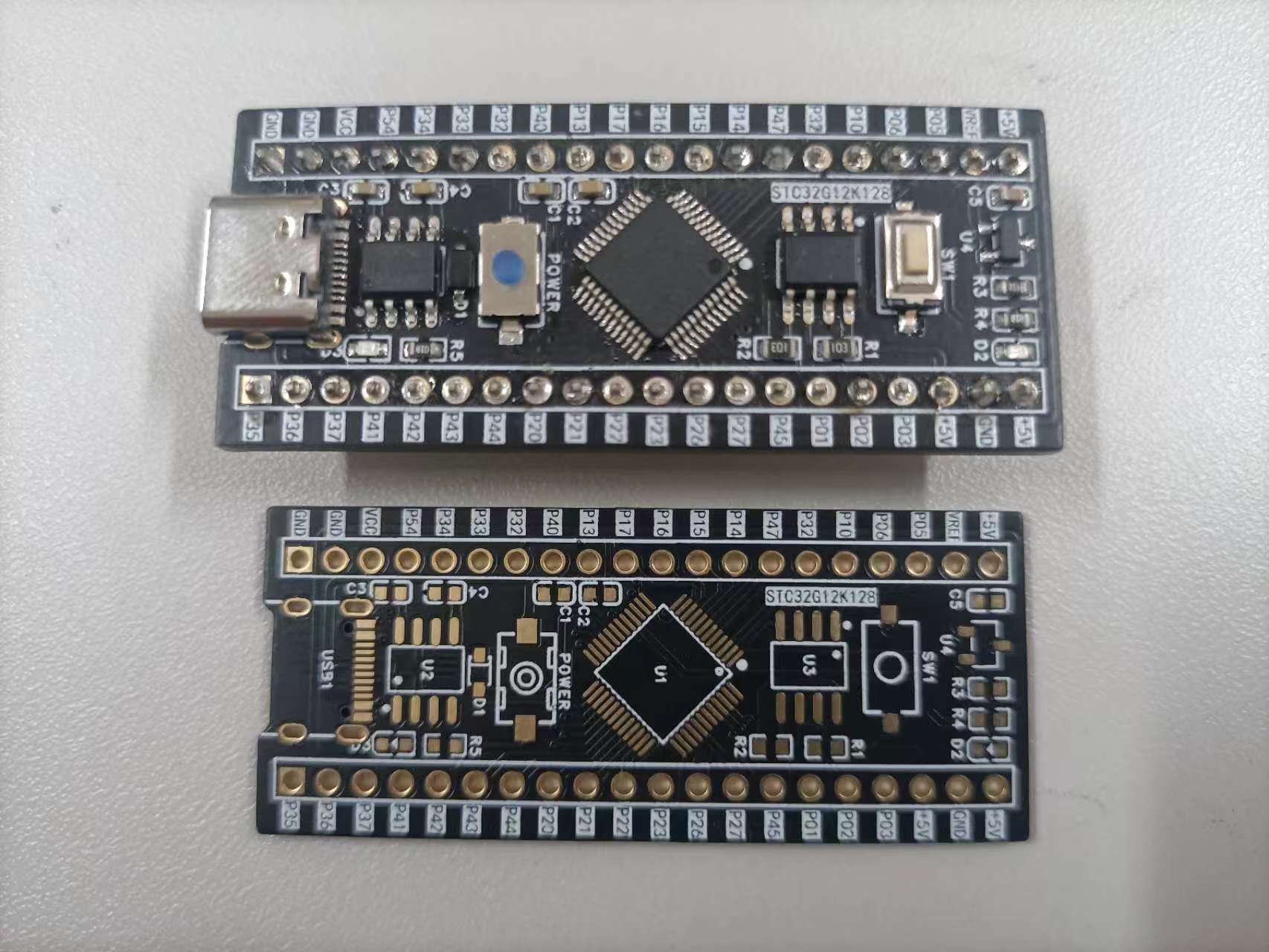
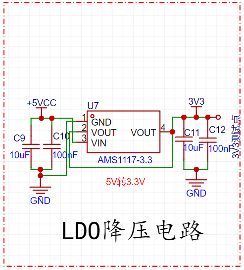
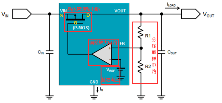
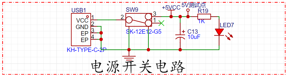
 ( Hardware circuit schematic design) The AMS117 LDO step-down circuit is a low-dropout linear regulator (LDO) with a fixed output voltage, providing a high-precision, stable output voltage. The AMS117 is based on a feedback regulation circuit using a reference voltage source and an error amplifier. It uses a differential amplifier to compare the output voltage with the reference voltage, adjusting the output voltage to maintain stability. An LDO typically consists of four main components: a voltage divider sampling circuit, a reference voltage, an error amplifier circuit, and a transistor adjustment circuit. Voltage divider sampling circuit: The output voltage is acquired through resistors R1 and R2; Reference voltage: Generated by a bandgap voltage reference to minimize the impact of temperature changes on the reference; Error amplifier circuit: The acquired voltage is input to the inverting input of the comparator and compared with the reference voltage (the desired output voltage) at the non-inverting input, and the comparison result is amplified; Transistor adjustment circuit: The amplified signal is output to the control electrode of the transistor (the gate of a PMOS transistor or the base of a PNP transistor), so that the amplified signal (current) can control the transistor's on-state voltage, which is a negative feedback adjustment loop. Power switch circuit: When the 2PIN-Type-C is plugged in, the switch is turned on, VBUS and +5V are conducted, and LED7 lights up for indication; when the switch is turned off, LED7 turns off. Buzzer circuit: 8-pin digital tube circuit PCB diagram, 3D diagram, physical diagram, software code design, button selection experiment, buzzer experiment, marquee experiment, interrupt experiment. Bilibili video link: JLCPCB & STC32G12K128 core board
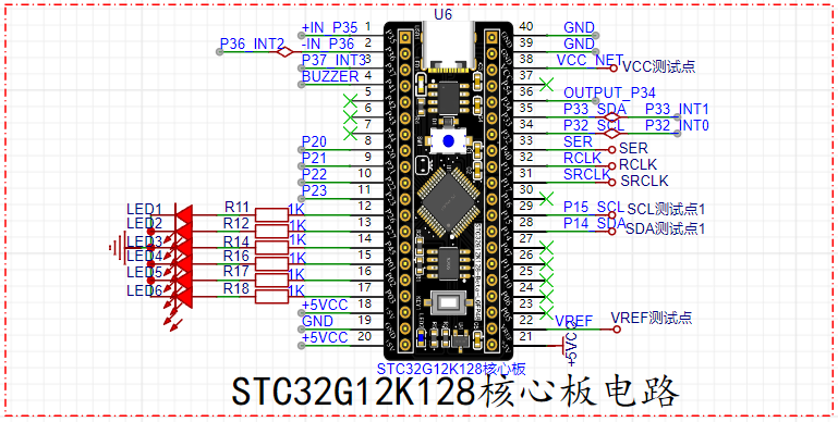


All reference designs on this site are sourced from major semiconductor manufacturers or collected online for learning and research. The copyright belongs to the semiconductor manufacturer or the original author. If you believe that the reference design of this site infringes upon your relevant rights and interests, please send us a rights notice. As a neutral platform service provider, we will take measures to delete the relevant content in accordance with relevant laws after receiving the relevant notice from the rights holder. Please send relevant notifications to email: bbs_service@eeworld.com.cn.
It is your responsibility to test the circuit yourself and determine its suitability for you. EEWorld will not be liable for direct, indirect, special, incidental, consequential or punitive damages arising from any cause or anything connected to any reference design used.
Supported by EEWorld Datasheet
EEWorld
subscription
account

EEWorld
service
account

Automotive
development
community

Robot
development
community

About Us Customer Service Contact Information Datasheet Sitemap LatestNews


Room 1530, 15th Floor, Building B,
No.18 Zhongguancun Street,
Haidian District,
Beijing, Postal Code: 100190
China
Telephone: 008610 8235 0740
 京公网安备 11010802033920号

 DCG015


