I. Project Description
A headphone amplifier, or headphone power amplifier, can drive headphones with higher internal impedance and enhance the music listening experience. However, commercially available headphone amplifiers are several times more expensive than their cost price, lack USB-C input, and make it impossible to design the internal circuitry yourself. Therefore, this project aims to create a powerful, low-cost portable headphone amplifier.
>>>Click here to watch the demo video<<<
II. Open Source License
GPL 3.0
III. Project Features
[x] Can drive headphones with a maximum impedance of 600 ohms, even low-sensitivity headphones;
[x] Compact size, easy to carry;
[x] Powered by USB Type-C, supports PD/QC protocols;
[x] Carefully designed circuitry ensures minimal interference for a truly HI-FI music experience.
IV. Project Attributes
This project is being publicly released for the first time and is my original work. This project has not won any awards in other competitions.
V. Project Schedule
February 17, 2024:
Project created, schematic drawing started . February
18 , 2024:
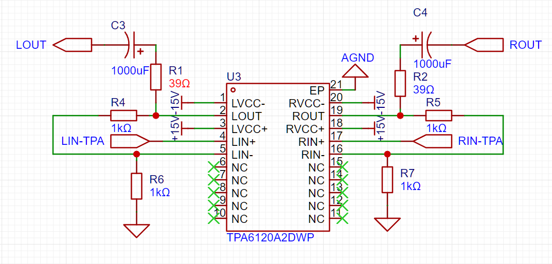
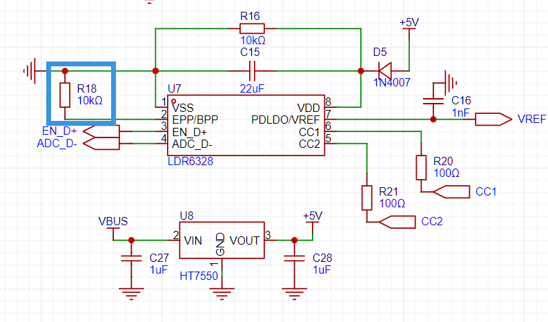
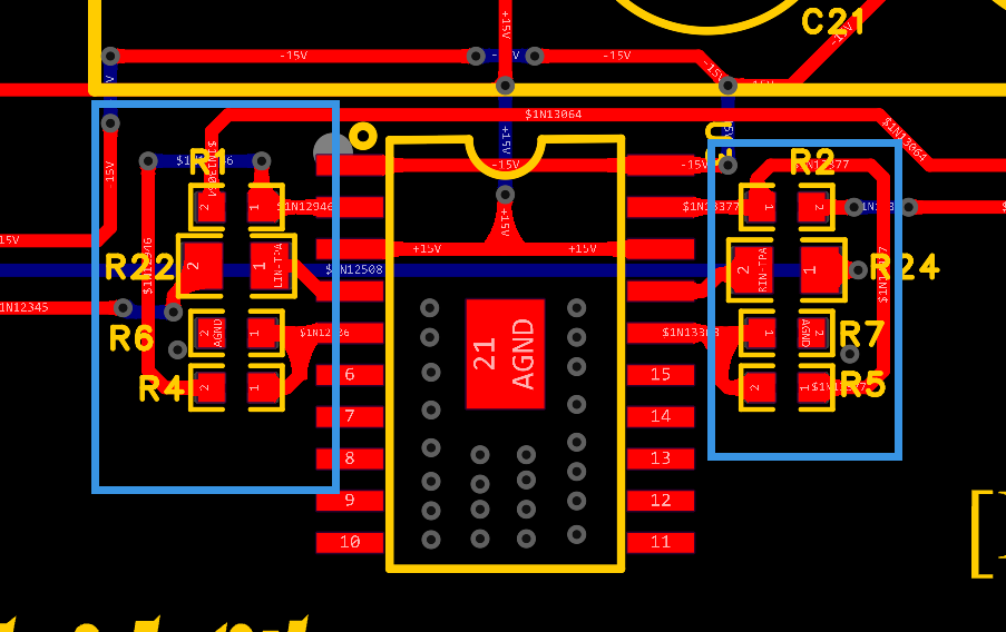
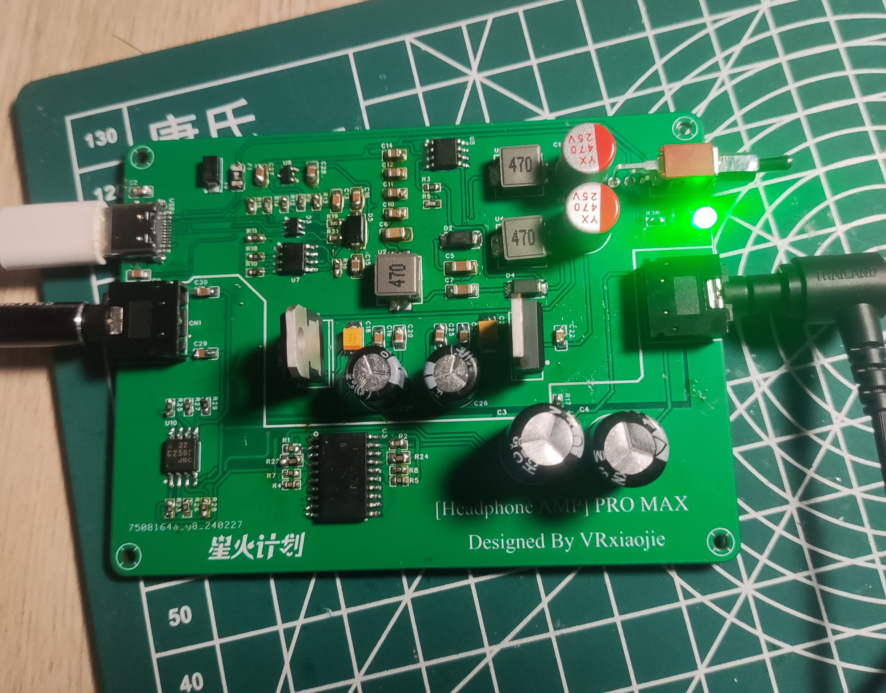
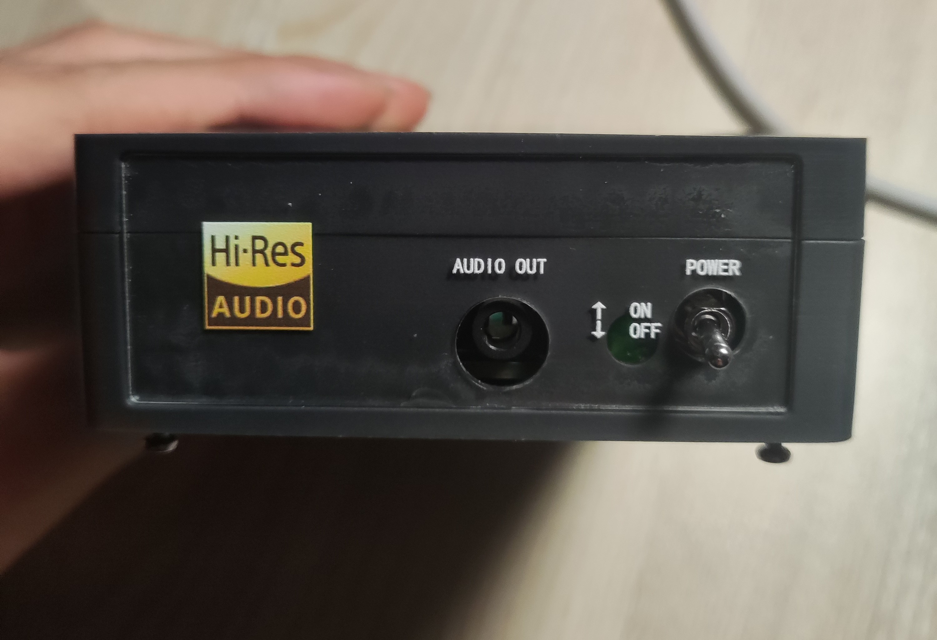
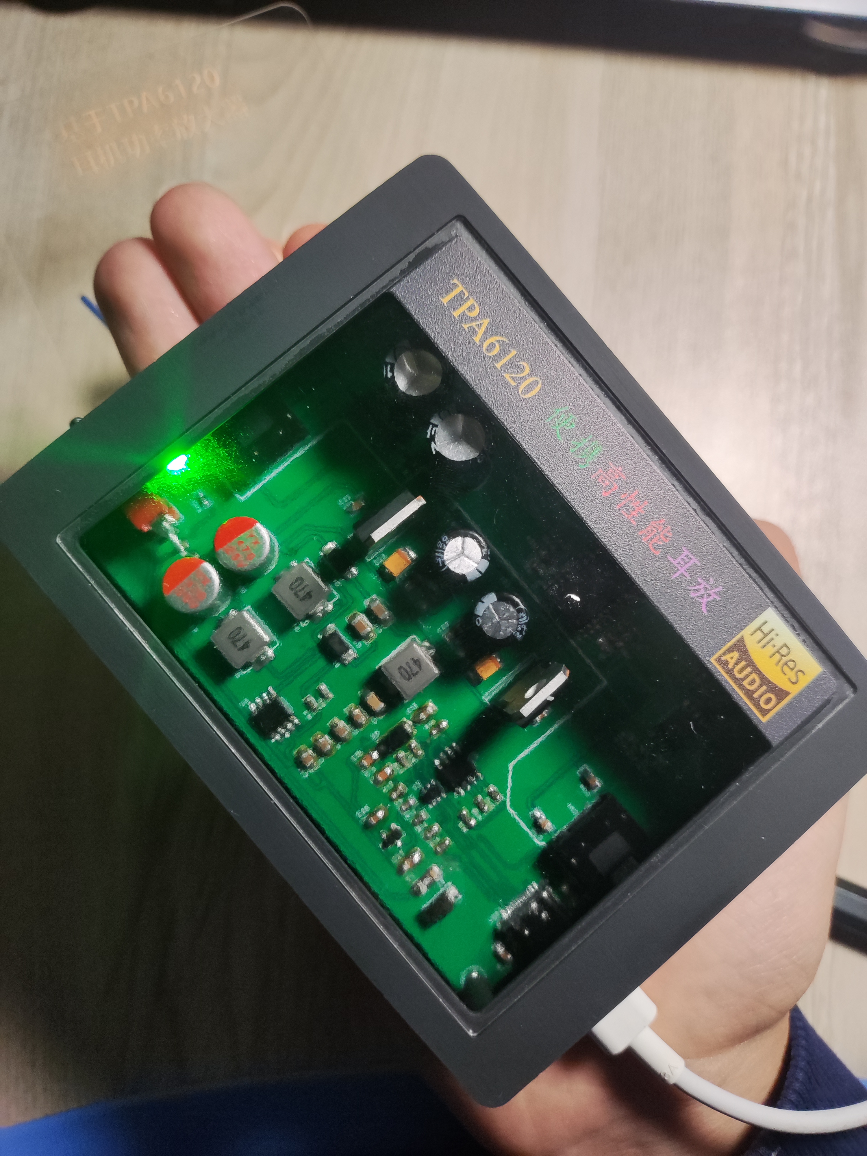
Schematic drawing completed. February 19 , 2024: PCB design started . February 27, 2024: Design completed, PCB layout optimized. February 29, 2024 : Soldering started. March 2, 2024: Physical testing completed, functions normally; casing and panel design started. March 5, 2024: Casing and panel design completed . March 8, 2024: Casing and panel installation completed; project completed! VI. Design Principles 1. TPA6120A2 Audio Power Amplifier: This is the core of the project. According to the datasheet, ±15V power supply performs better than ±5V; therefore, ±15V power is used. 2. NJM5532 I/V Conversion 3. LDR6328 PD/QC Decoy Input: Pin 2 of the LDR6328 is connected to a pull-down resistor, indicating that the adapter is decoyed to try 12V, 9V, and 5V outputs sequentially, prioritizing PD and then QC. 4. The voltage is converted to ±17.5V by a SPEIC circuit, and then regulated to ±15V by an LDO to provide the operating voltage for the op-amp. VII. Precautions: Note that the resistor next to the TPA6120 should be placed close to the chip pins (within the blue box). Recommended power-on and wire insertion order: First connect the audio output device (phone/computer, etc.) to the AUDIO IN interface, then connect the AUDIO OUT interface to the headphones, then plug in the Type-C power supply, turn on the power switch, and finally put on the headphones. This is to prevent the "pop" sound caused by power-on from damaging hearing. If you have a solution, please leave a comment! Thank you! It is best to use a power bank/phone charger that supports 9V/12V voltage and QC/PD protocol. Testing with a computer's USB 3.0 interface showed a voltage of around 5V, with very noticeable background noise, which is suspected to be due to insufficient power supply from the computer's USB interface. VIII. Project Reference Circuit: Refer to the designs of the following two experts, thank you. The TPA6120 desktop headphone amplifier and TPA6120A2 headphone amplifier also referenced the datasheets of the chips used: LDR6238, XL6007E1, and TPA6120A2. IX. Physical Demonstration : During operation, the bare board appears as a 3D-printed shell with a transparent top panel. The front and rear panels are shown. The headphones used for testing were Sony WH-1000XM4, and the soundstage was found to be wider and the details richer. X. Notes: 10.1 Originally, I wanted to make a portable headphone amplifier with a Bluetooth + battery combination. However, halfway through, I realized that adding more batteries significantly reduced its portability (increasing its size) and required frequent charging (the measured power was approximately 1.5W; assuming a 5000mAh lithium battery, it theoretically only lasts about ten hours). Therefore, I changed my approach and made a smaller headphone amplifier that can be used on a desktop or carried around. It uses Type-C power and is powered by a power bank when out and about, or a mobile phone charger. Additionally, "portable" refers to its small size (only palm-sized) and light weight. This is my second open-source project ( 10.2 ). It's been a month and a half since I first encountered JLCPCB, so there are bound to be shortcomings. I hope to learn from and exchange ideas with experienced developers in the comments section. This project participates in the Spark Program. If you think it's good, please like and bookmark it, and leave your opinions and suggestions in the comments section. Welcome to replicate and improve this design! Possible features to be added after 10.3 (version 2.0): [ ] Type-C digital input, built-in DAC decoding


 京公网安备 11010802033920号

 PDM505HA


