As of December 25, 2023, I have updated the second-generation portable beacon light and modified and optimized the 3D model in the project and attachments.
I have created a QQ group for electronic exchange, and all enthusiasts are welcome to join: 527972069.
I. Project Introduction:
At the beginning of this year, a light-up prop in the game "OUTER WILDS" caught my attention, inspiring me to bring it from the virtual world to real life. To this end, I invested a lot of time designing the circuit and model, going through multiple iterations. Now, I have finally successfully created a satisfactory portable light.
II. Functions and Design Scheme:
This work uses a 12V lithium battery pack to provide power to the linear regulator and LED light strip. The linear regulator reduces the 12V voltage to 3.3V to power the control module. The control module integrates single-channel touch stepless dimming, 433MHz wireless reception and decoding functions, giving the work remote control and touch dimming capabilities. In addition, the circuit board is equipped with three series-connected lithium-ion charging management modules, which can charge the 12V lithium battery pack. This piece is not only highly aesthetically pleasing but also functional, serving as a desktop decoration and outdoor lighting. Furthermore, the circuit board integrates a lithium battery charging management module, allowing for battery charging via a Type-C charging cable.
Below is a simplified structural diagram of the circuit design:

III. Material Preparation:
This section lists some of the components needed to assemble this piece.
Accessory
Quantity
and Purpose:
M6 Flat Head Screws 6mm
6
for Fixing Handle;
M3 Studs 30mm+6mm
3
for Internal Bracket Assembly;
M3 Studs 13mm+6mm
6
; M3 Socket Head Screws 15mm
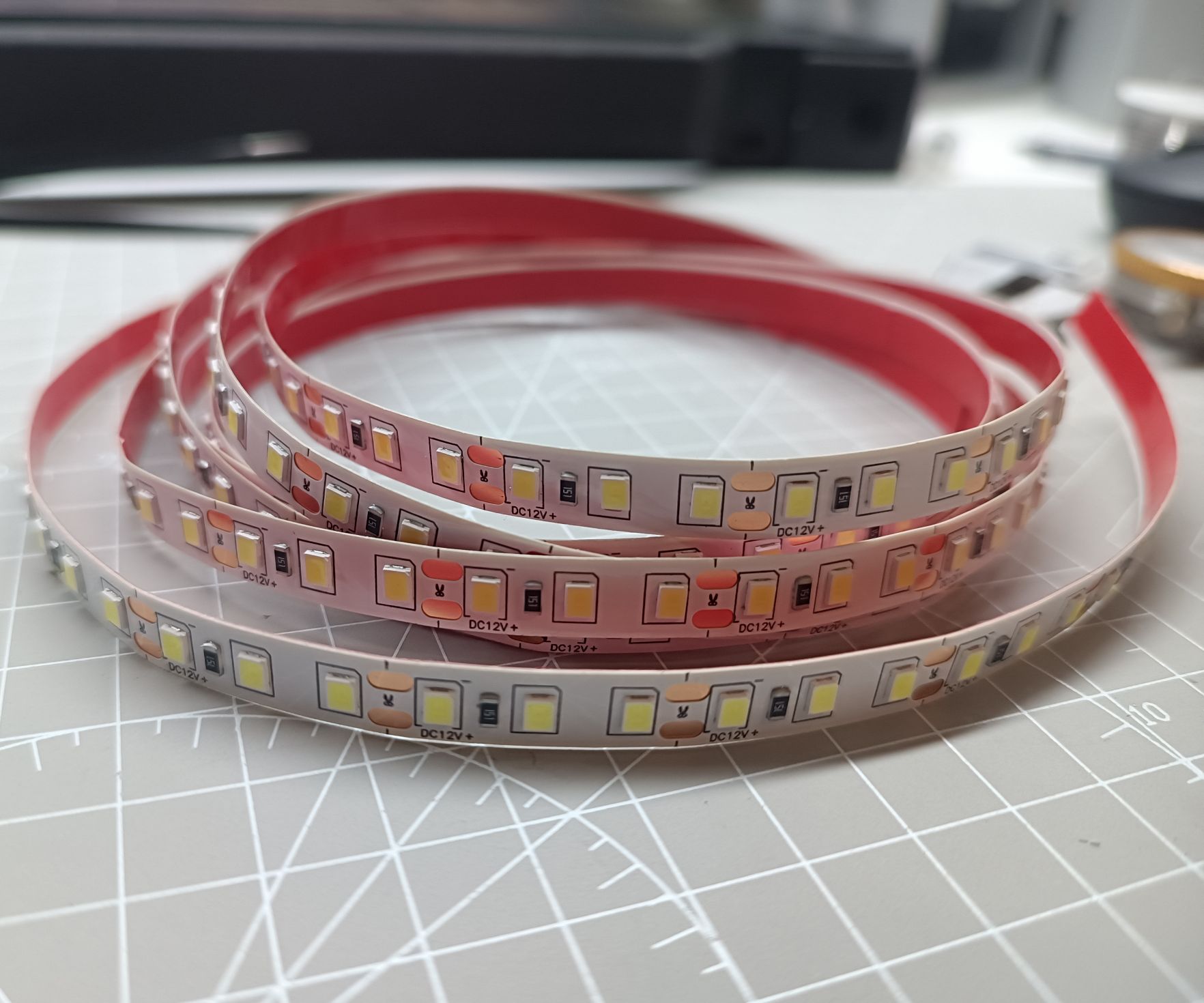
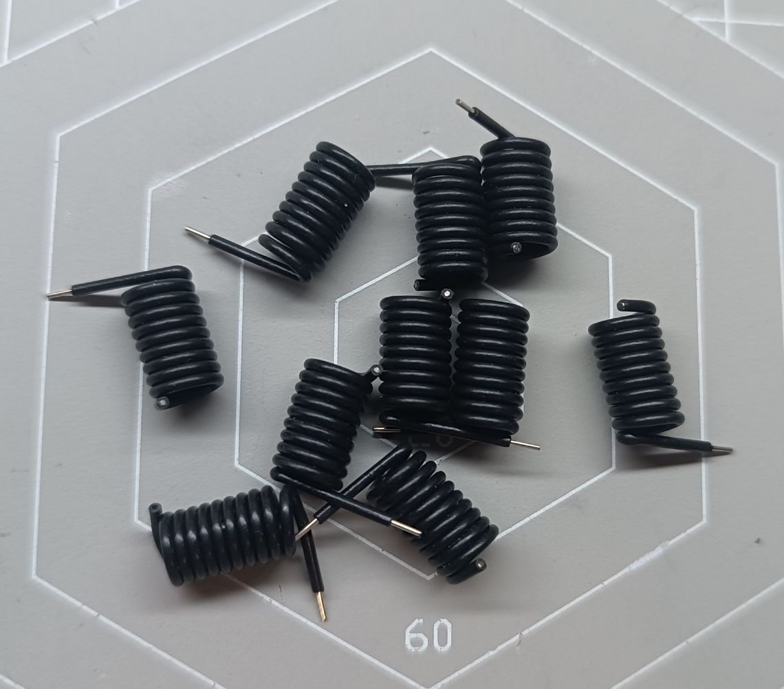
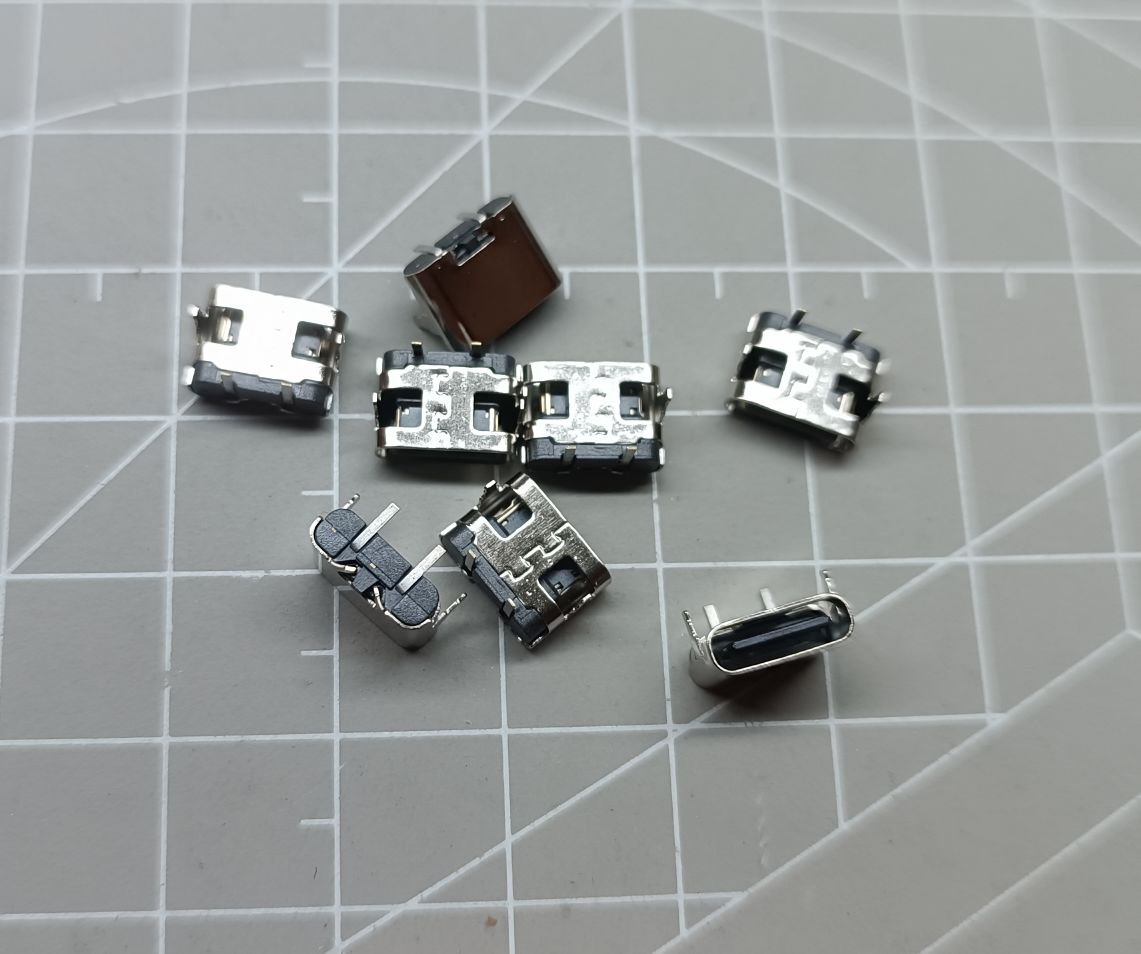
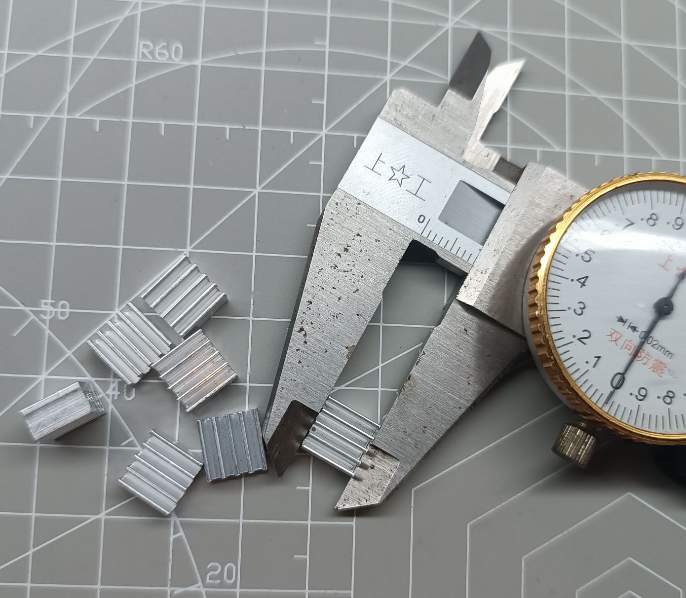
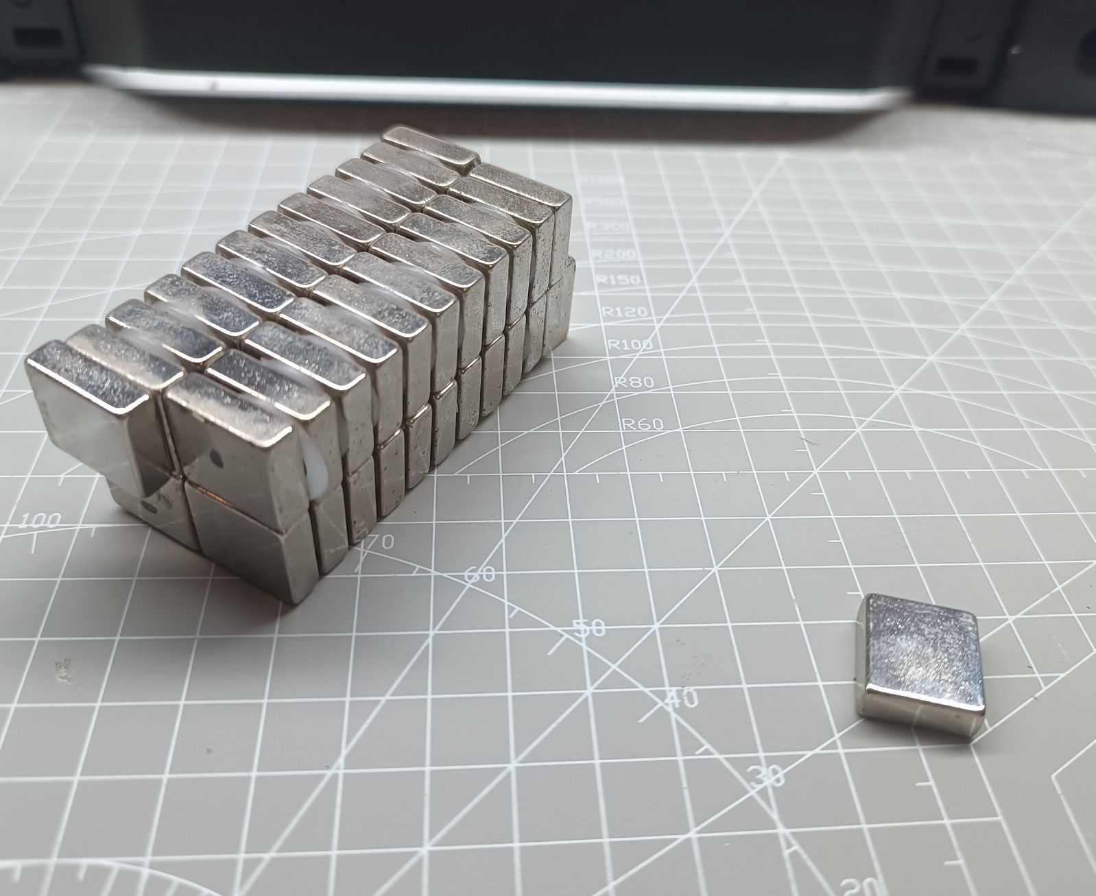
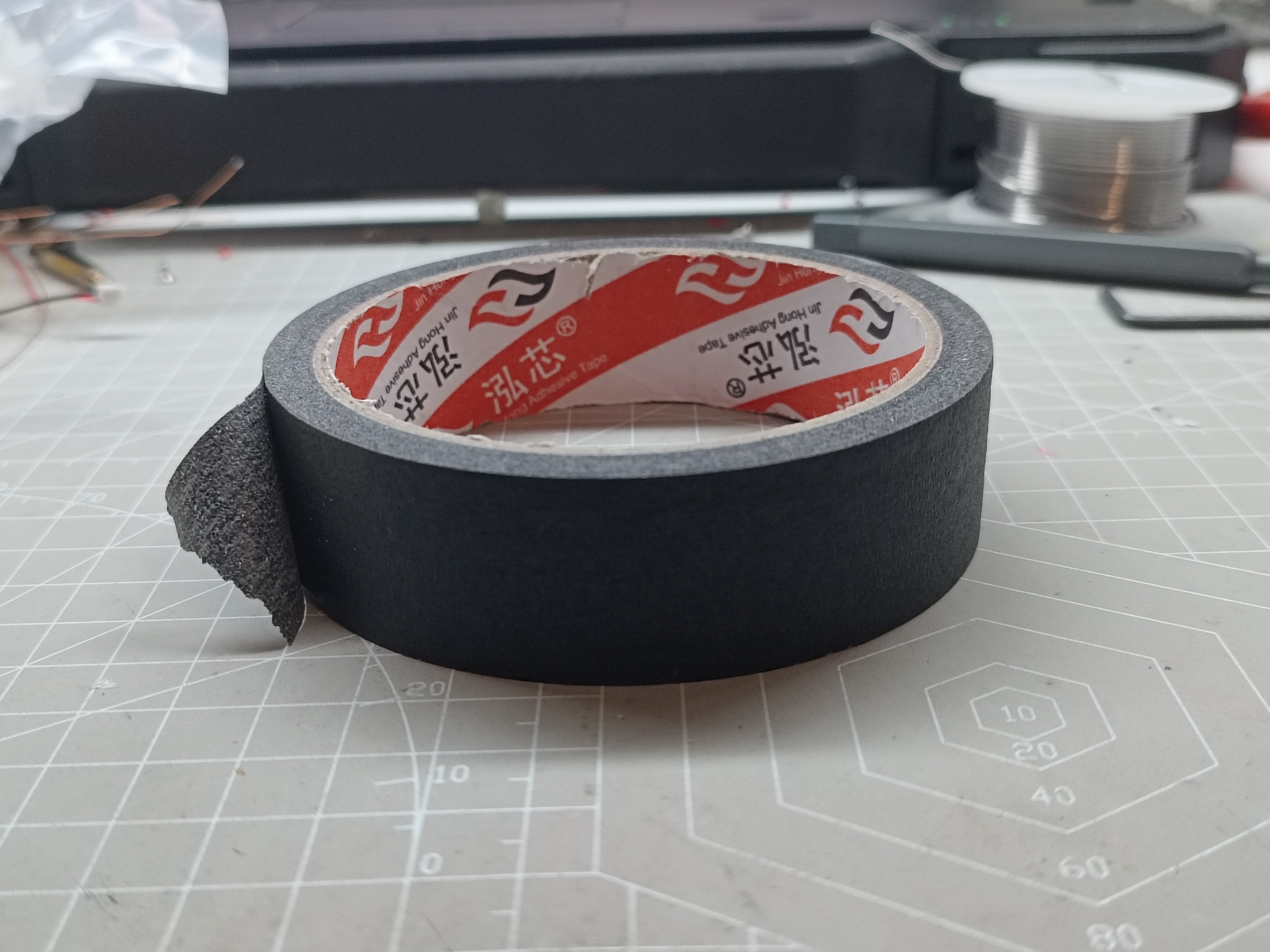
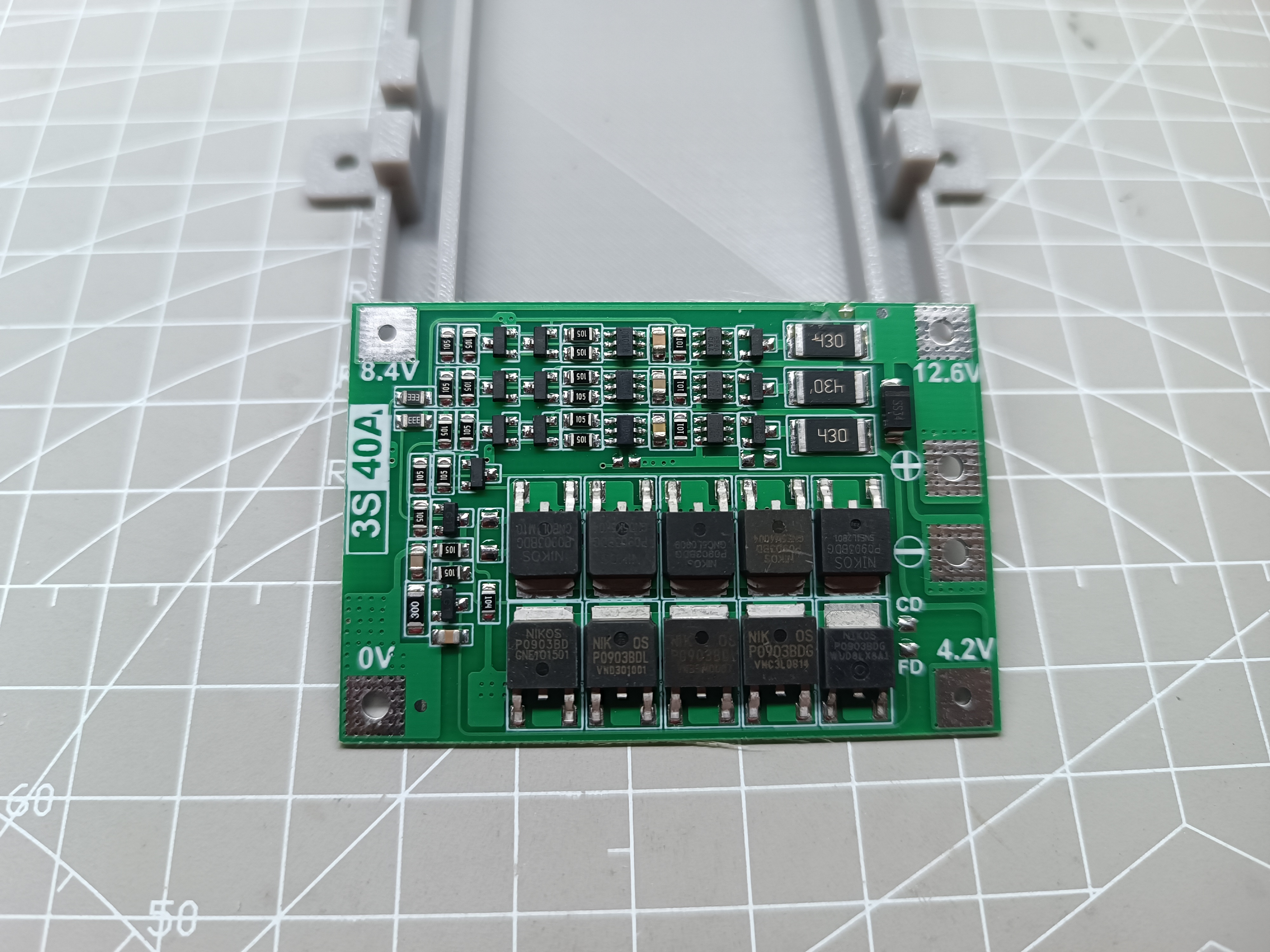
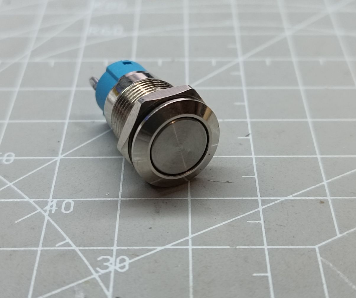
3 ; M3 Socket Head Screws 8mm 4 ; M3 Stainless Steel Washers 4 ; M3 Nuts 1 ; M3 Self-Tapping Screws 8mm 2 for Fixing Battery Compartment ; M2 Self-Tapping Screws 10mm 4 for Remote Control Installation and Fixing; M2 Self-Tapping Screws 5mm 4 for Fixing Main Circuit Board; Circuit Board 1 for Remote Control Receiver, Stepless Dimming, and Charging Management; Remote Control Transmitter Board 1 for Remote Control Transmitter; Three-Cell Series Lithium Battery Protection Board 1 for Lithium Battery Equalization Charging, Overcurrent, and Over-Discharge Protection; 12mm Metal Self-Locking Switch 1 for Main Switch; XH 2.54mm 2-Pin Terminal Block 5 for Circuit Connection; 18650 Lithium Battery 3 for Power Supply ; Heat Sink and Thermal Grease 1 for Charging Chip Heat Dissipation; Copper Foil Tape and Wires 1 for Touch Sensing ; T9000 Glue 1 for Adhesive Lampshade; Black Masking Paper 1 for Internal Light Shielding; 3D Printed Parts 1 for Outer Shell ; Lamp Strip: 6000K Color Temperature 12V LED strip. Self-adhesive backing; strip can be freely cut to size. Antenna: Both transmitting and receiving antennas use 433MHz spring antennas. Charging connector: Type-C 2-pin horizontal connector. Heatsink: 9*9*5 aluminum heatsink. Adhesive backing is recommended. Magnet: 17mm*15mm*6mm (L*D*H) neodymium magnet. Copper foil tape: Copper foil tape acts as the touch sensing electrode. Cut 20mm*30mm pieces of copper foil tape, solder them to the TCH circuit, and attach them to the back of the sensing surface. Black masking tape: Used for internal light blocking. The gray casing is slightly translucent; black masking tape inside reduces light transmission. Lithium battery protection board: Uses a three-cell series-connected lithium battery protection board, which provides equalization charging, undervoltage, overvoltage, and overcurrent protection. Metal self-locking switch: Uses a 12mm metal self-locking switch for controlling the overall circuit. IV. Hardware Introduction: Battery Charging Management: This product uses the IP2325-3S chip for battery charging management. This chip is a synchronous switching boost charging management chip for three series-connected lithium batteries. When connected to a 5V power supply, it can charge a three-cell series-connected lithium battery pack. The IP2325-3S has rich protection functions to ensure stable and reliable module operation. The chip integrates an NTC temperature control function, which can detect the battery temperature by connecting a resistor to pin 4 (NTC). When the battery temperature is too high or too low, the charging management chip will stop charging the lithium battery pack. Please note that the charging management chip generates heat during charging. It is recommended to use a 9*9 (mm) heatsink attached to the top of the chip for good heat dissipation. When using the heatsink, ensure that the height of surrounding components does not exceed that of the charging management chip and avoid the heatsink causing short circuits to surrounding components. Single-Channel Touch Stepless Dimming: This product uses the single-channel touch chip RH6618A to achieve stepless dimming. This chip's stepless dimming PWM frequency is up to 25KHz, making the dimming process smoother. The RH6618A incorporates a capacitive touch sensor circuit, enabling touch dimming via the TCH pin. During operation, the POUT pin outputs a PWM signal, connected to the gate of an NMOS transistor to drive a high-power LED strip. Notably, this chip requires no programming and includes built-in mode configuration pins: MOD1 and MOD2. Changing the levels of these two pins switches between stepless dimming modes. A high level configuration pin is connected to VDD or left floating; a low level configuration pin is grounded. Pin 5 (TCH) of the RH6618A is the touch sensing pin, which can be connected to a copper foil in series with a resistor. The copper foil is attached to a non-metallic sheet; touching the sheet dims the light. For high/low level control of dimming, a signal line connecting a diode and a resistor in series can be connected next to the copper foil. A high level input to the stepless dimming chip dims or switches the circuit; a low level stops dimming.

It is important to note that other circuit layouts should be minimized near the TCH pins to improve the anti-interference capability of touch dimming.
Wireless Remote Control Circuit: The
433MHz remote control circuit, as a common wireless remote control solution, transmits information by transmitting and receiving electromagnetic waves at a frequency of 433MHz. In this project, I used an integrated encoder-transmitter chip (LBT12B), a receiver chip (LR680J), and a decoder chip (FJ1527-M3) to achieve complete wireless remote control functionality. These chips are characterized by low cost, simple peripheral circuitry, and low power consumption; the 433MHz transmitter module only requires a 3V button battery to operate.
In the wireless remote control module, the input electrical signal undergoes a process of encoding, transmitting, receiving, decoding, and outputting electrical signals to achieve remote control functionality. The decoder chip (FJ1527-M3) is equipped with a multiplexer switch. Pressing the switch twice consecutively within one second will enter the pairing mode, which supports adding a remote control circuit. In pairing mode, simply pressing the remote control transmit button once completes the pairing process. If you press and hold the switch for more than 8 seconds, the decoding chip will clear the pairing record, making the previously paired remote control unrecognizable. To re-identify, you need to pair again.
To increase the remote control distance of the 433 remote module, please ensure there is no copper plating around the transmitting and receiving antennas (ANT).
Linear Regulator:
Since the project uses a 12V lithium battery pack, and some control chips have lower rated voltages, the 12V voltage needs to be reduced to 3.3V to power the control chips. Here, I used a stable linear regulator—ME6118A—to convert the 12V power supply to a voltage that the chip can safely and normally operate at.
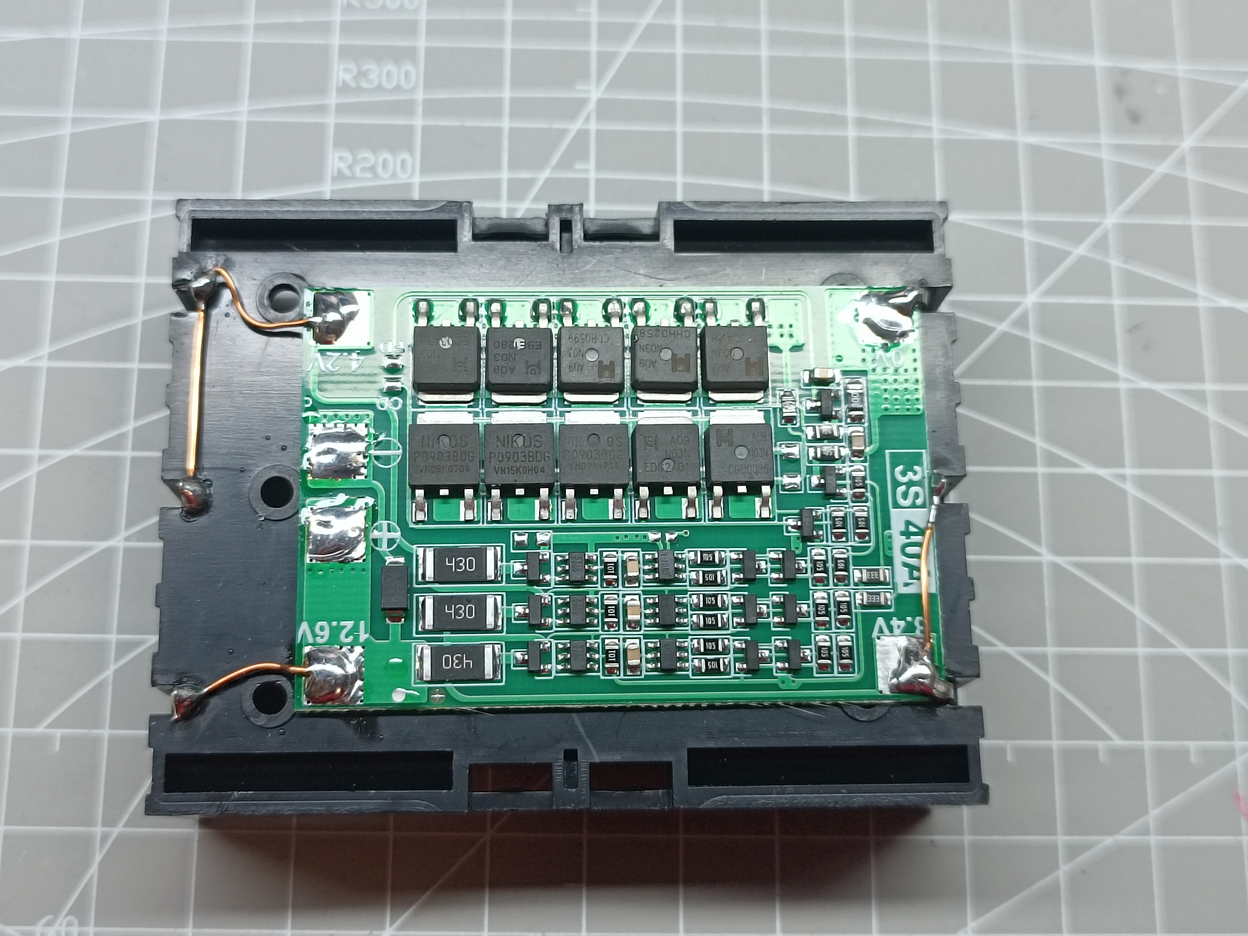
Three-cell series lithium battery pack:
The lithium battery pack is homemade and has a built-in charging protection module. For details, please refer to my other open-source project: FM3450C Three-cell series lithium battery charging protection chip.
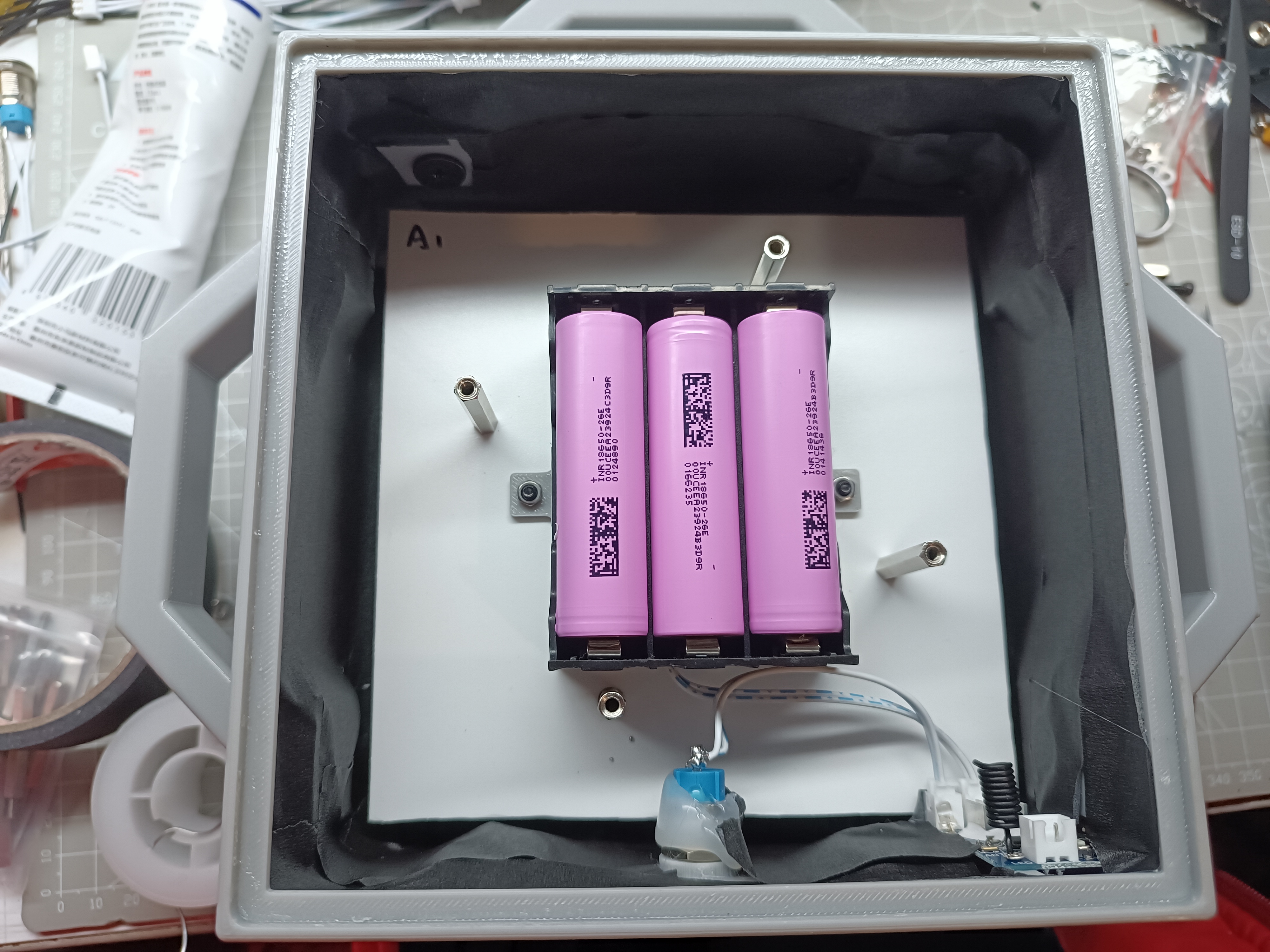
The second-generation lithium battery pack uses 18650 lithium batteries, a lithium battery charging equalization protection board, a battery compartment, and 3D printed parts, and can be assembled through simple soldering.
Circuit diagram drawing:
I used JLCPCB EDA to design the schematic and PCB layout. These two diagrams are relatively simple and very suitable for beginners to try DIY. In the schematic diagram, I have marked some capacitors that require attention to voltage rating. These capacitors are marked with an asterisk (*) after their values. It is recommended to use capacitors with a voltage rating of 16V or higher to ensure circuit stability.
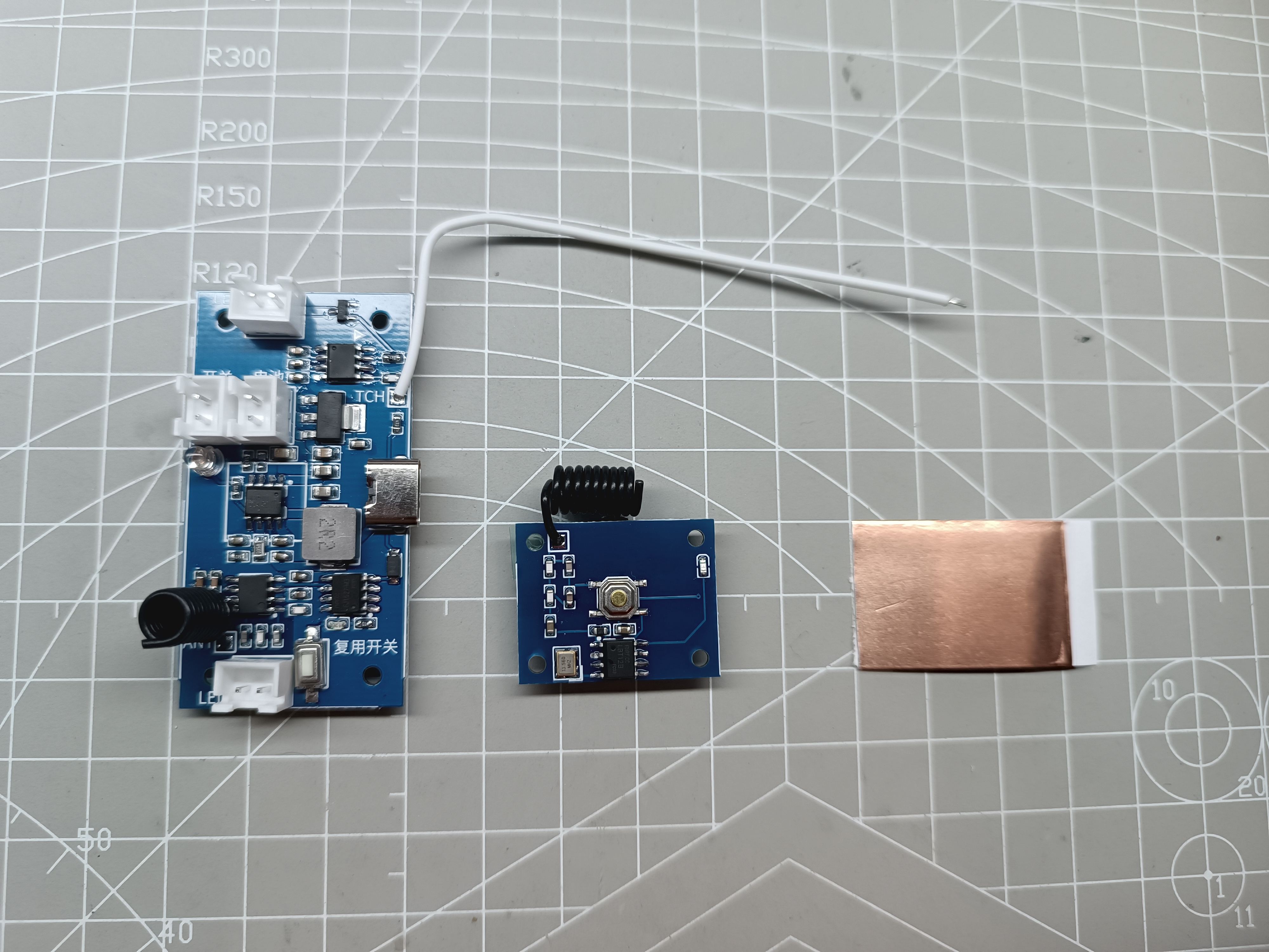
Below is a picture of the actual board:
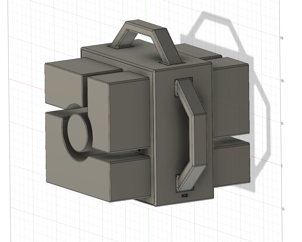
V. 3D Model Design:
Autodesk Fusion 360 is a modeling software that is very suitable for beginners, and this model was also designed using it.
After the design is completed, use an FDM printer to print out the 3D physical picture.

VI. Production Process:
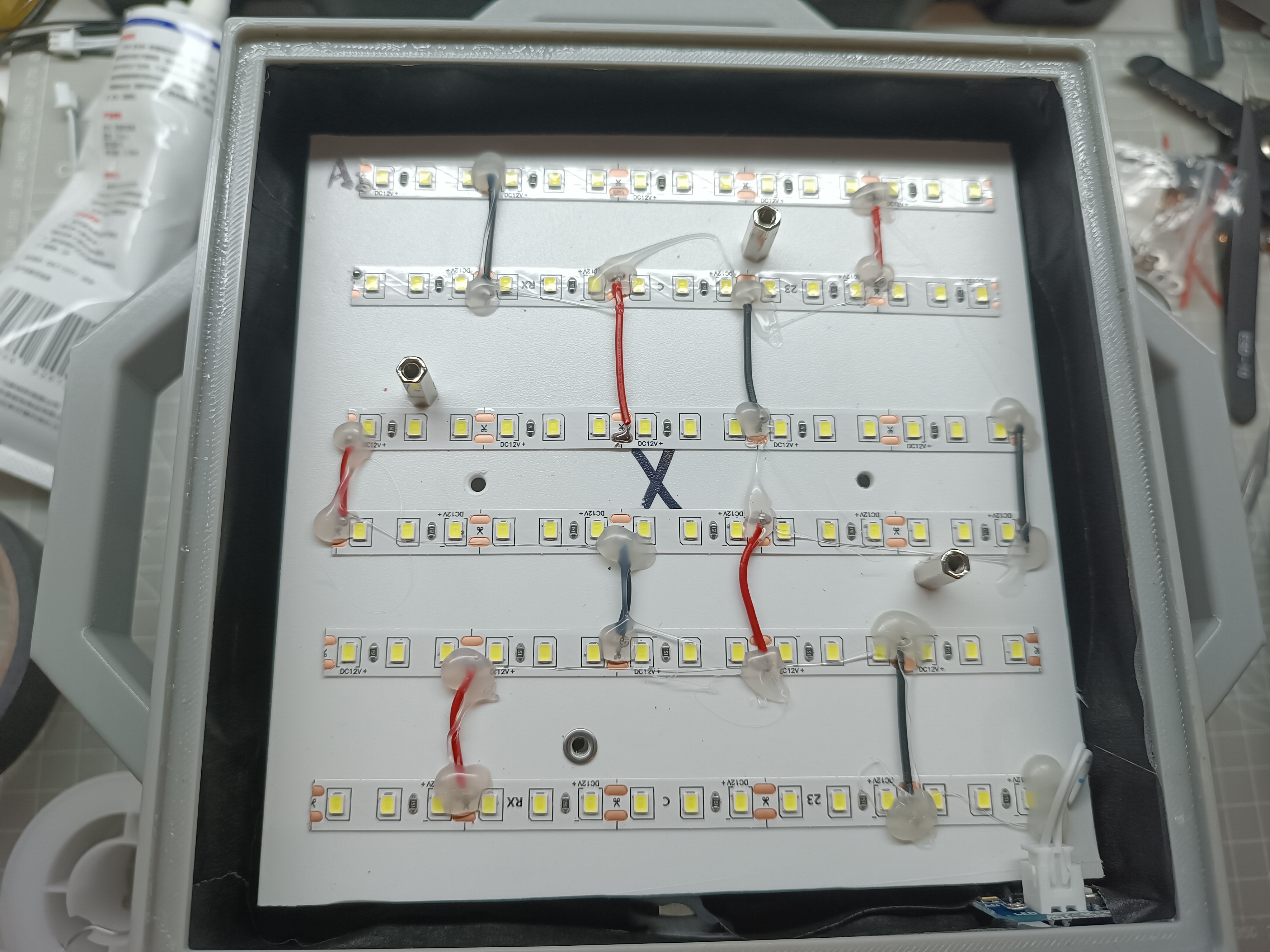
LED Board: Cut the LED strip to an appropriate length, attach it to the base plate, then connect it in parallel with wires, and finally fix it with hot melt glue.
The base plate can be the one included in the 3D model. Alternatively, you can buy two 140mm*140mm*2mm plastic plates and drill holes yourself.

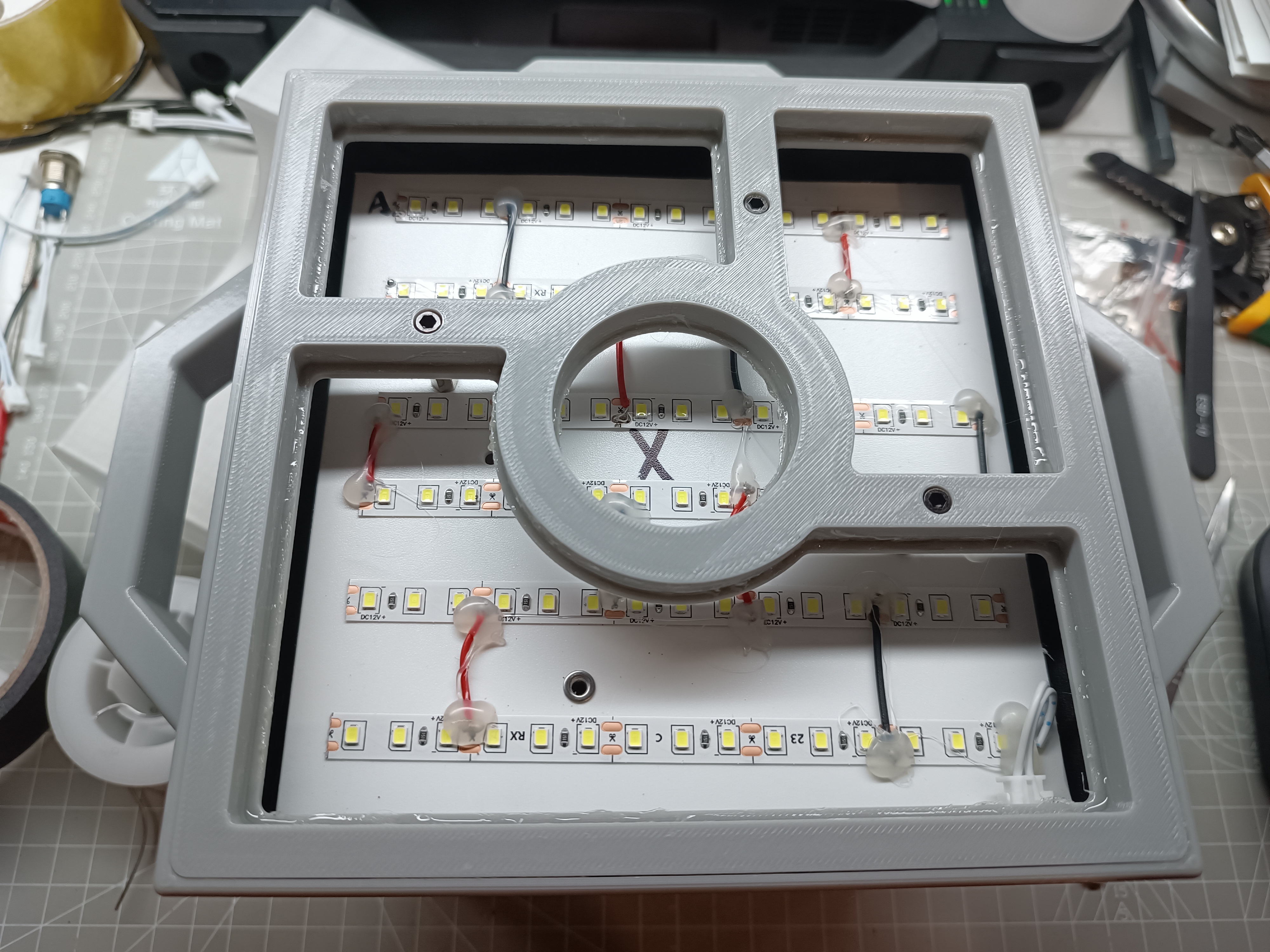
Fix the handle, copper foil tape, circuit board, neodymium magnet, and copper pillar to the model.

Cover the inside of the model with black masking tape, install the lampshade (it needs to be fixed with glue, T9000 glue can be used, the lampshade can be installed last), and apply hot melt glue to the screw holes of the switch to prevent loosening.
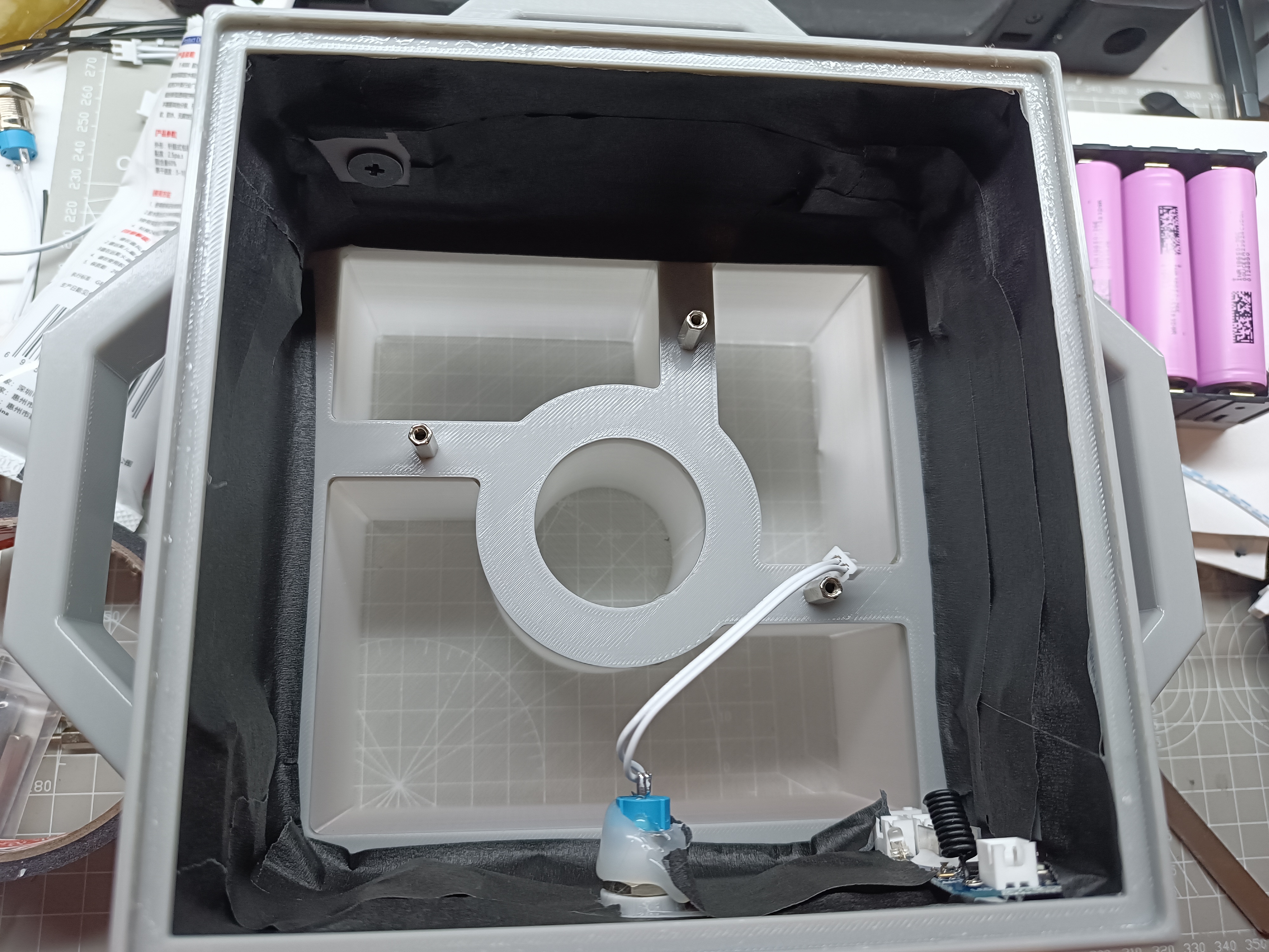
Install the lamp board, battery, washer, and studs. Then connect the wiring. (At this stage, you can start the module to test whether the circuit can work properly.)
Cover with the other lamp board and fix it with studs.
Cover with the lampshade fixing piece and install the screws. After applying glue to the lampshade fixing piece, install the lampshade.
After it solidifies, it can be used.
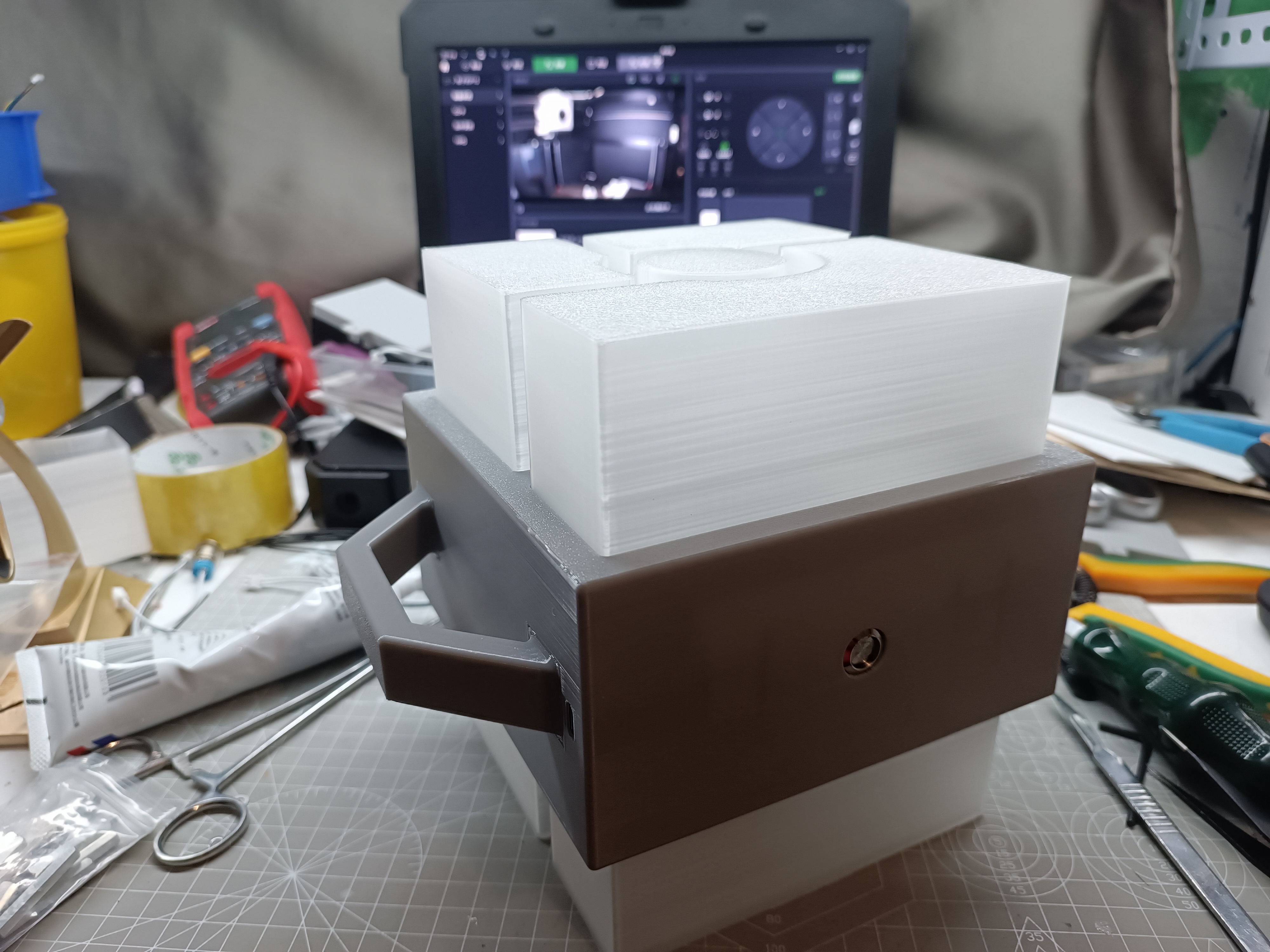
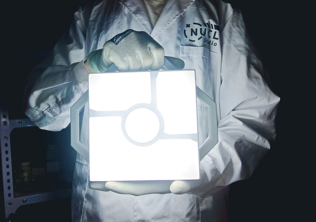
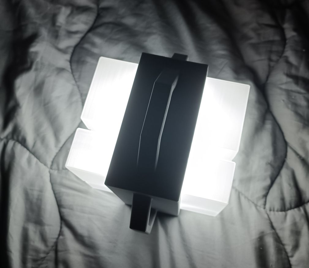
The following is a display of the finished product:

VII. Conclusion:
This portable lamp is not only a real-world embodiment of the spirit of games, but also my tribute to game creativity. My goal is to let more people feel the unique charm and inspiration of games through this work. You can scan the QR code at the beginning of the article to watch the demonstration video of the portable lamp. This project has been published on the LCSC Open Source Hardware Platform. I will continue to update and improve the project. Those interested can search for me on Bilibili by entering the article title or click the following link to find the video: [LCSC Open Source] I Replicated the Beacon Light from Outer Wilds.
Finally, I sincerely thank the LCSC Open Source Hardware Platform for providing me with free consumables support, which gave me more opportunities to verify the solution. Thank you for your attention and support!


 京公网安备 11010802033920号

 HB11190


