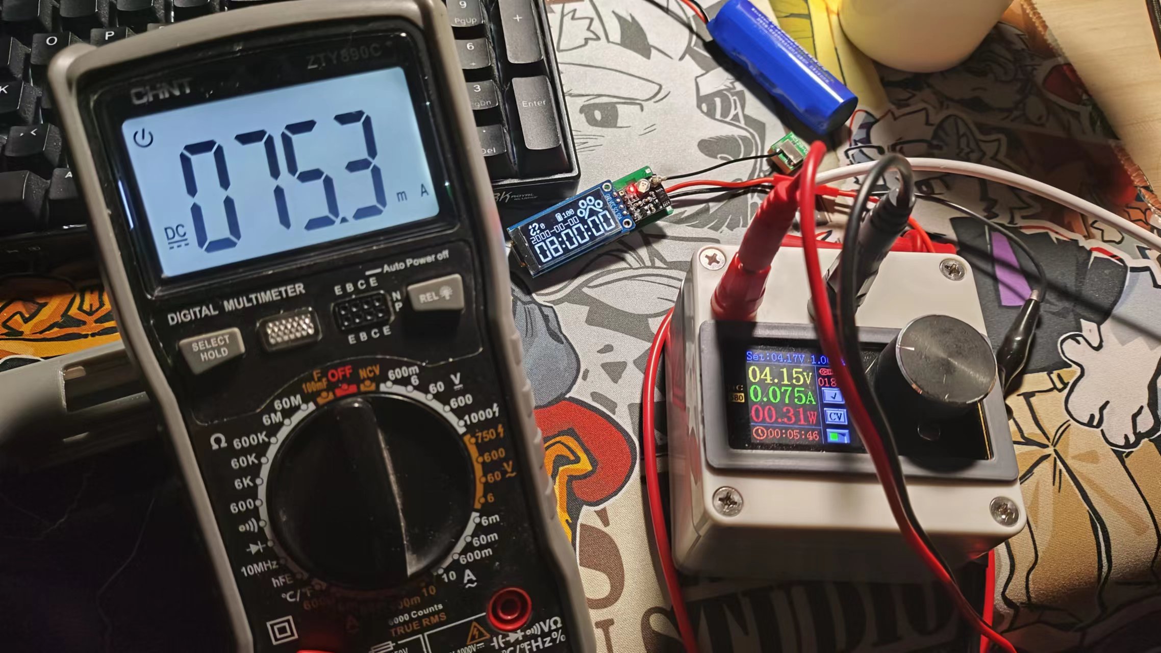
 This version incorporates regional power control, achieving one-button power-on, power-on hold, and automatic power-off without adding buttons. It can also independently disconnect power to components other than the main controller to achieve ultra-low power consumption.
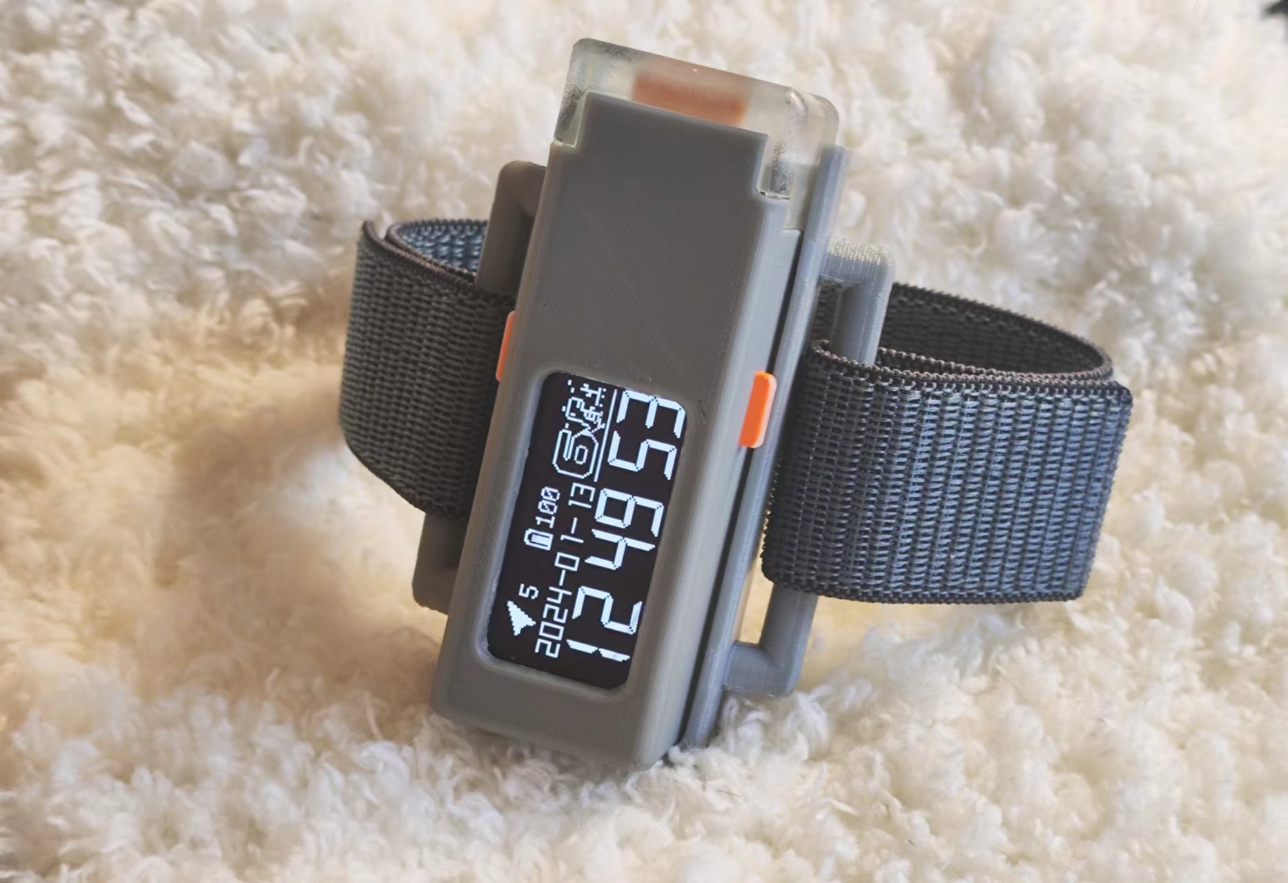
  This version features an expandable shell design, allowing it to be worn or attached to more locations by connecting expansion modules (a possible extension: solar charging).
 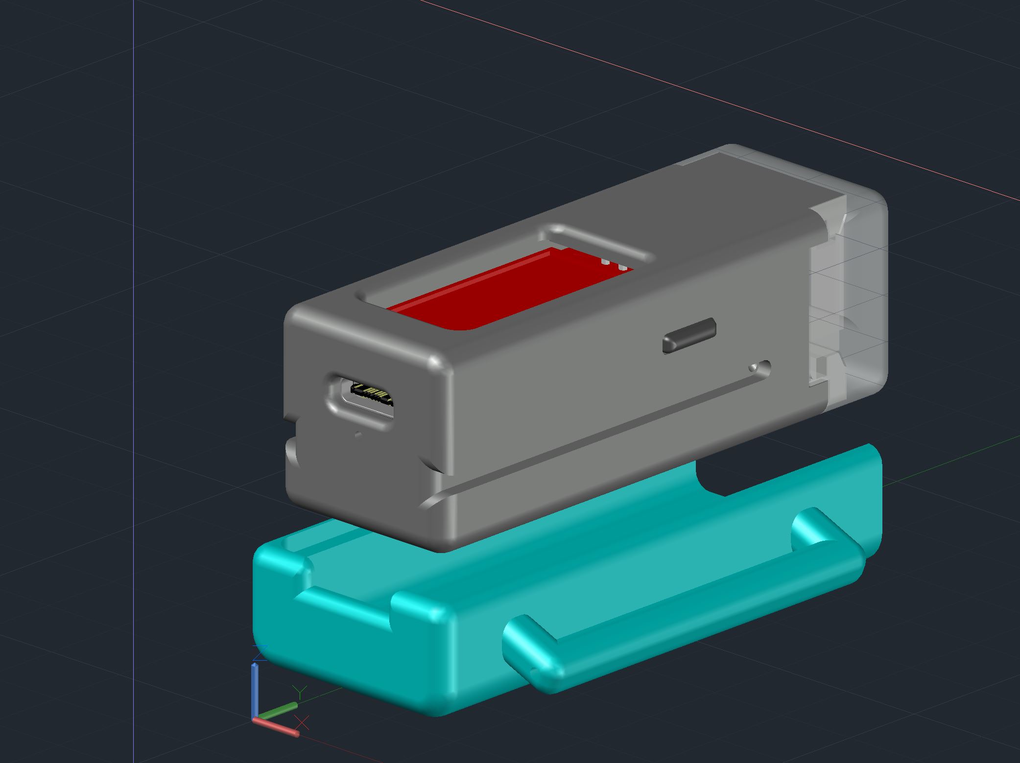 PCB uses a 3D stacked design, making the structure more compact.


 Regarding soldering: The temperature sensor, magnetometer, and barometer are temperature-sensitive devices and require special protection before soldering.
  The pins need to be shortened beforehand, and the soldering should be rounded to avoid scratching the battery.
 2. Positioning latitude and longitude display interface: After successful positioning, it displays the latitude and longitude information of the current location.
 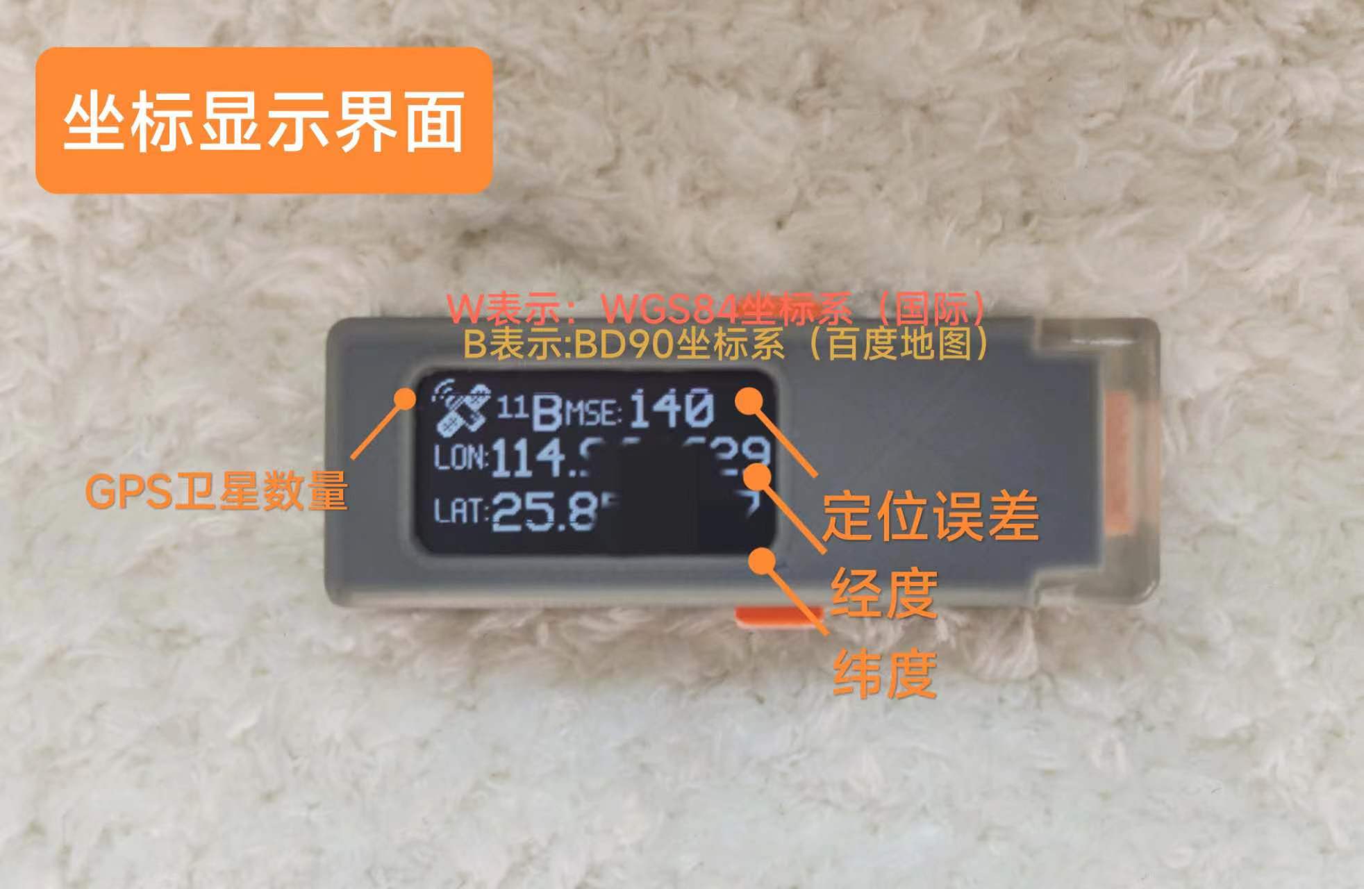 3. Compass Display Interface:
 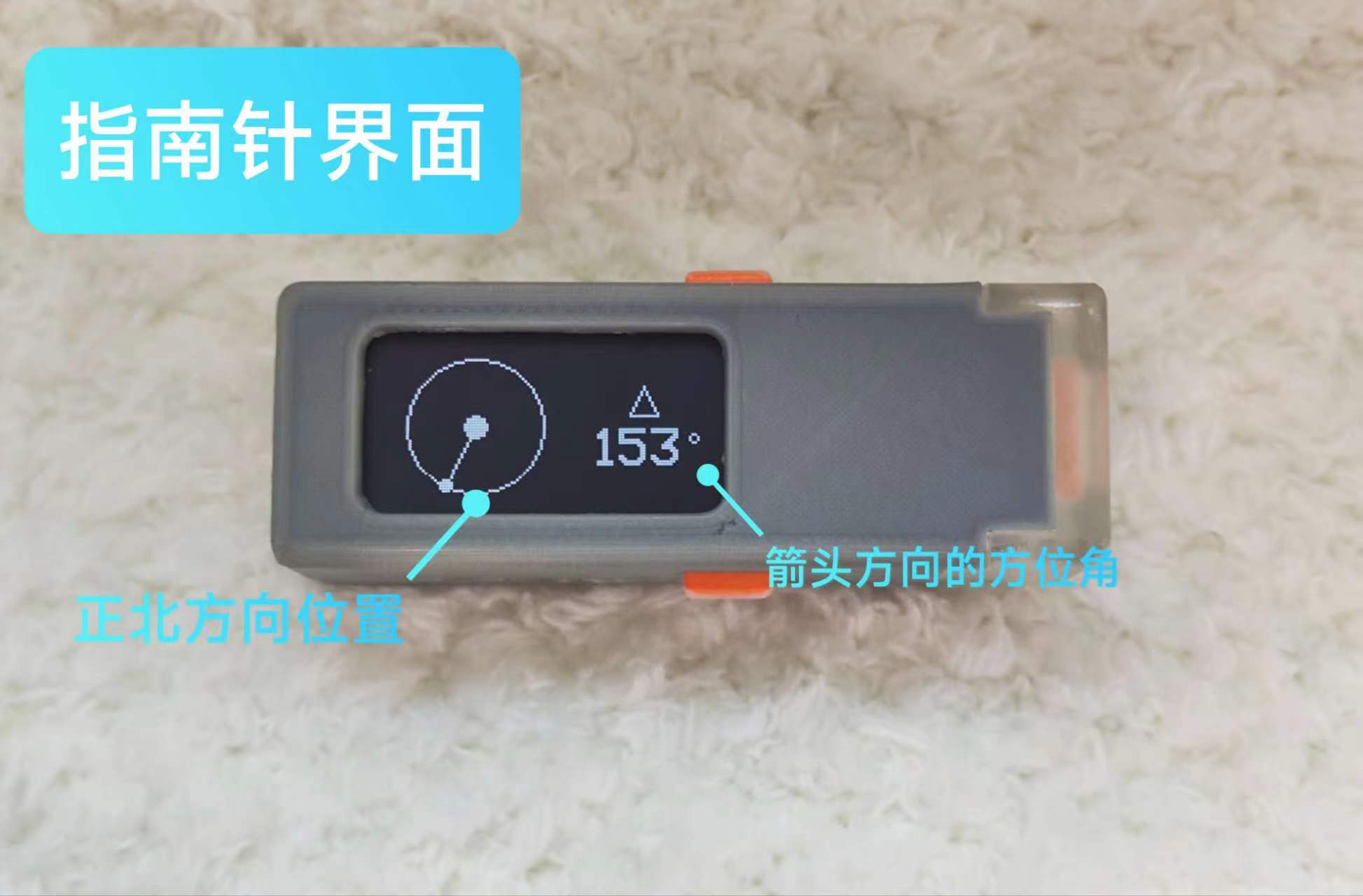 4. Altitude Display: Displays altitude and air pressure data.
 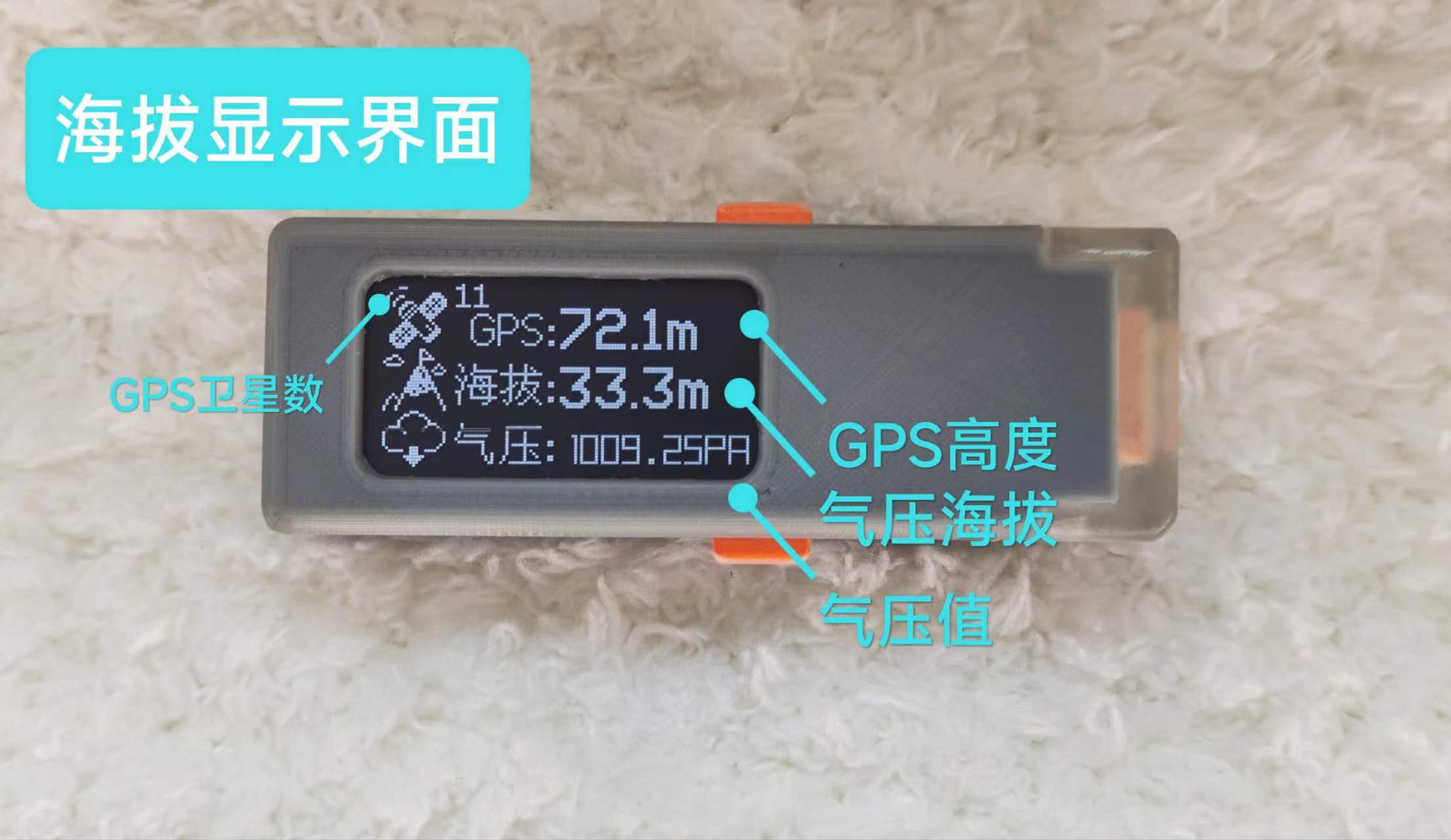 5. Temperature and Humidity Display: Displays temperature and humidity data obtained by the sensor.
  6. Flashlight Function Interface: Turns on the flashlight;
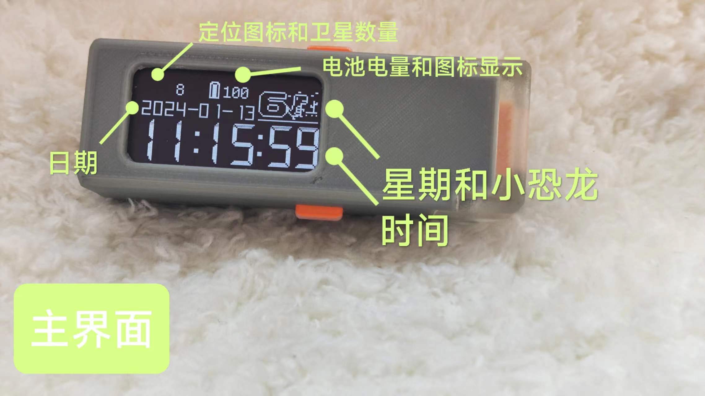
 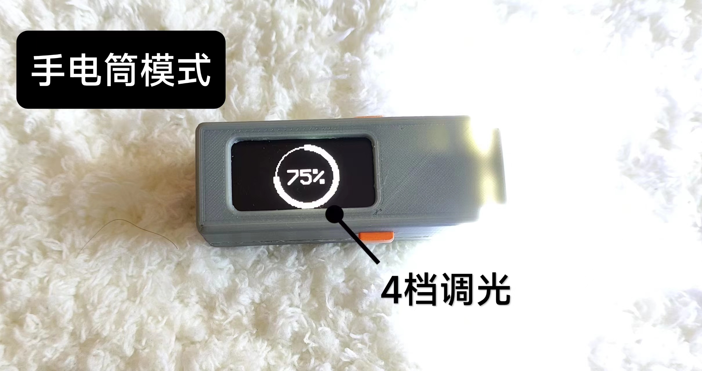 7. Always-on Display Interface: Simply displays the time.
  Features to be developed:
All reference designs on this site are sourced from major semiconductor manufacturers or collected online for learning and research. The copyright belongs to the semiconductor manufacturer or the original author. If you believe that the reference design of this site infringes upon your relevant rights and interests, please send us a rights notice. As a neutral platform service provider, we will take measures to delete the relevant content in accordance with relevant laws after receiving the relevant notice from the rights holder. Please send relevant notifications to email: bbs_service@eeworld.com.cn.
It is your responsibility to test the circuit yourself and determine its suitability for you. EEWorld will not be liable for direct, indirect, special, incidental, consequential or punitive damages arising from any cause or anything connected to any reference design used.
Supported by EEWorld Datasheet
EEWorld
subscription
account

EEWorld
service
account

Automotive
development
community

Robot
development
community

About Us Customer Service Contact Information Datasheet Sitemap LatestNews


Room 1530, 15th Floor, Building B,
No.18 Zhongguancun Street,
Haidian District,
Beijing, Postal Code: 100190
China
Telephone: 008610 8235 0740
 京公网安备 11010802033920号

 93LC66BIMSG


