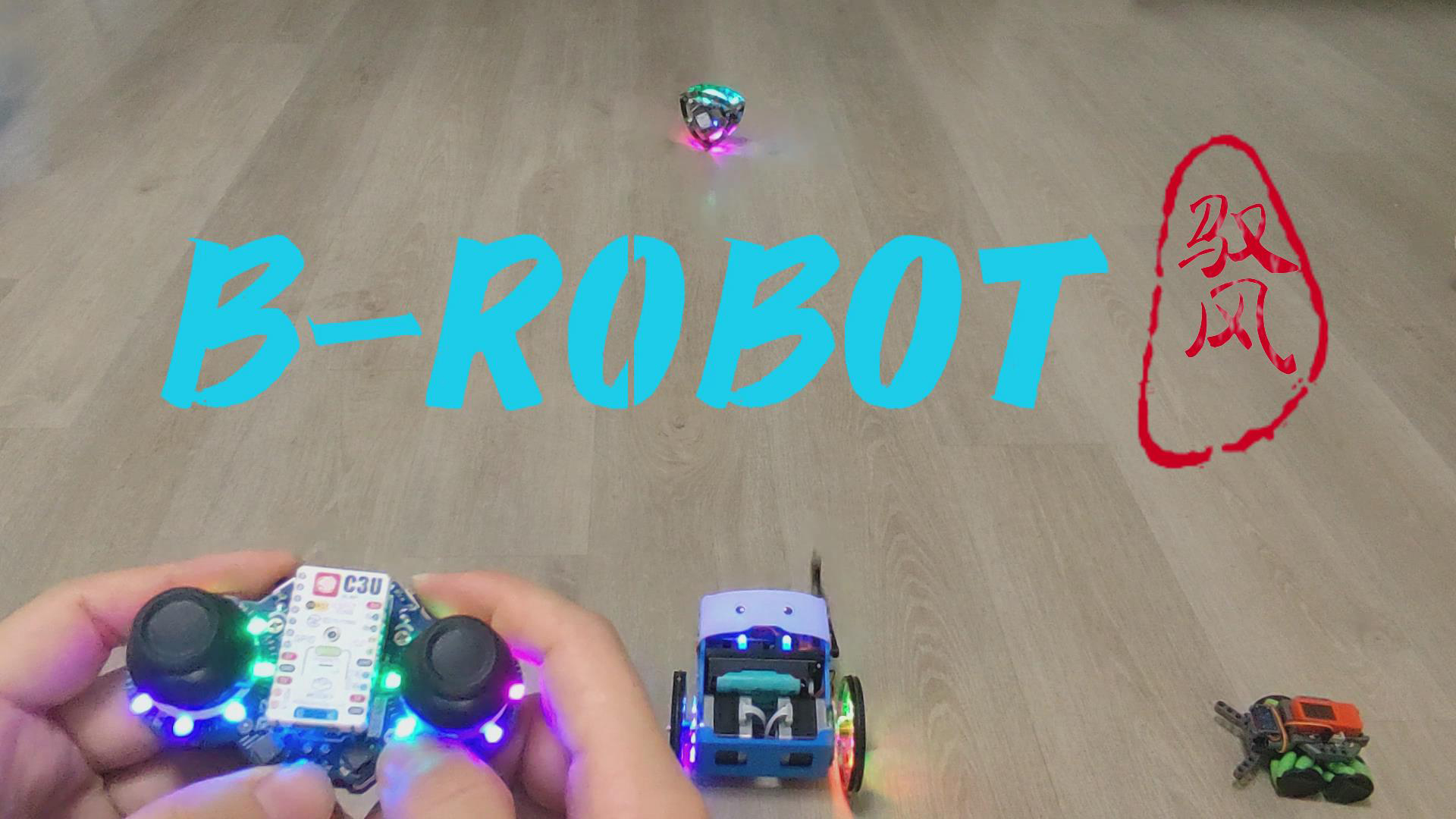
This general introduction

is based on the open-source project BROBOT, featuring a stepper motor self-balancing scooter. It offers multiple control methods, two dazzling colored light wheels for a cool look, smooth handling, and an attractive design. If it falls, the servo arms automatically help it get back up, making it very popular with children.
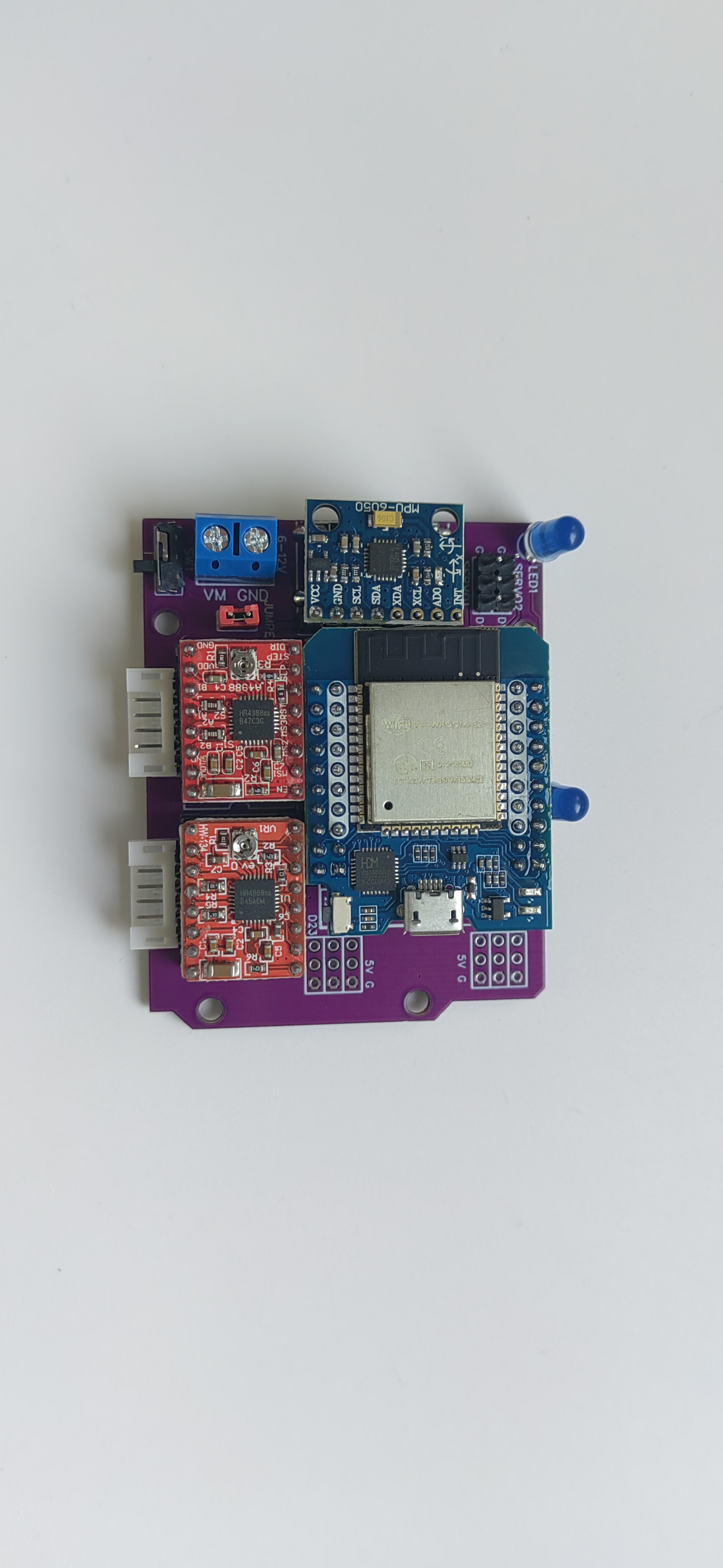
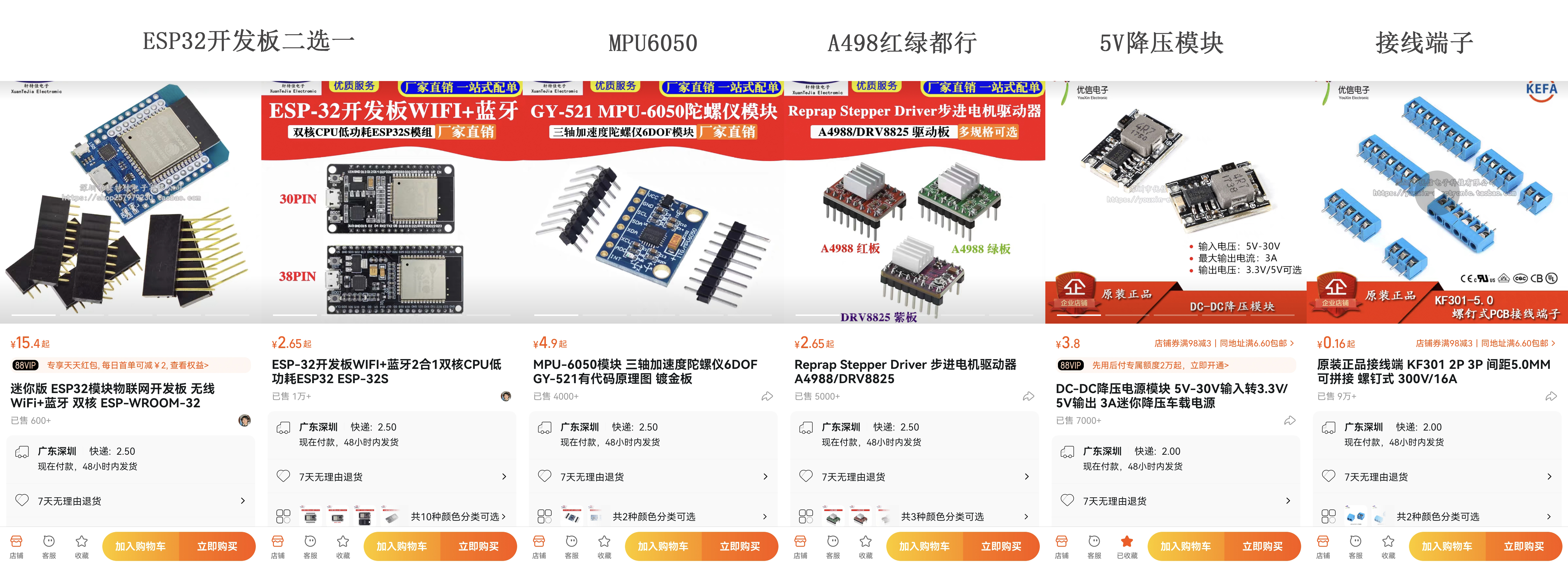
The main control board is an ESP32, with two 42 stepper motors driven by two A4988 modules. The arm servos use all-metal MG90S modules. An essential aesthetic enhancer is the RGB light ring. Power is supplied by three 18650 batteries. A simple battery box PCB was designed to eliminate the need to remove the batteries for charging, and it can be charged using a self-balancing charger. Two versions of the PCB were created, both with a fully modular design and universal program compatibility. The only difference is the development board shape: one is the commonly used rectangular ESP32-WROOM, and the other is a smaller ESP32-Mini development board, with some I/O interfaces provided for backup.
The scooter structure was modified and redrawn based on the original author's design, increasing battery space to accommodate the three 18650 batteries. Other features include custom-designed wheels and solutions for fixing the wheels to the motor shafts.
The original open-source website for B-ROBOT EVO2 is: B-ROBOT EVO 2. Much more than a self-balancing robot – jjrobots
Schematic and PCB Design.
This project requires controlling two stepper motors (5 I/Os), one servo, one RGB motor, one MPU6050 (I2C), and an unnecessary LED front light. The total number of I/O ports required is not large, and a modular design facilitates soldering and is convenient for beginners.
The PCB schematics for both versions are basically the same, except that version V2 has some additional I/O interfaces that can be used for other purposes. It features
a fully modular design, using the A4988 stepper motor driver. For ease of routing, a design using header pins and jumpers to switch microstepping is not used; the wiring is directly fixed to 1/8 microstepping of the A4988. If you want to change to a different microstepping setting, you need to make simple modifications to the wiring.
I also made a simple 3S battery box PCB with two XH2.54 connectors. The 2-pin connector connects to the expansion board, and the 4-pin connector connects to a plug, allowing direct charging of the battery with a balance charger (I used a regular B3 balance charger; make sure the wiring sequence matches your charger).
Alternatively, you can use a regular 3-cell series battery box and modify it by adding a 4-pin plug for the same effect, although soldering is more difficult.
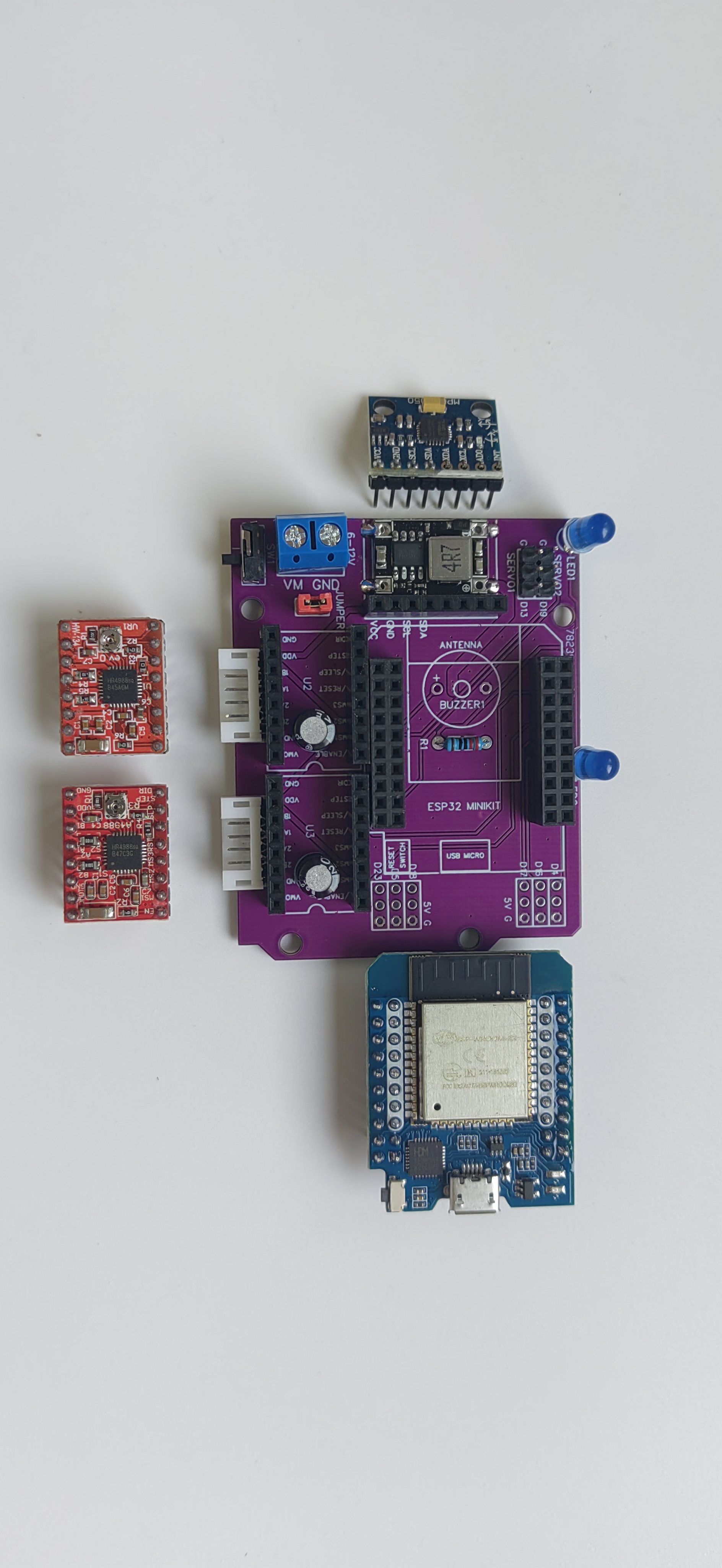
Because it consists of various modules, the PCB design is relatively simple, using the same UNO shape as the original author. All modules are arranged compactly. The following two images are schematics of the two versions: The
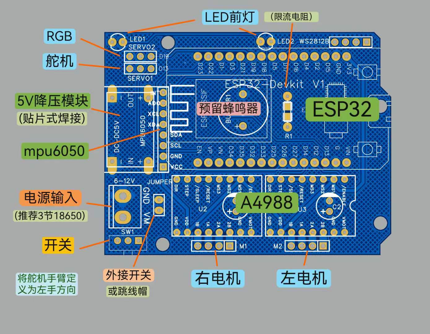
"external switch or jumper cap" in the image refers to the use of an external switch fixed to the right side panel of the balance scooter. The switch wire is plugged in here as the balance scooter's power switch. If this expansion board is used for other purposes, a jumper cap is plugged in here, and the small switch on the edge of the expansion board acts as the power switch.
The LED headlight and current-limiting resistor (any few hundred to 1K ohms) are only for easy identification of the front of the scooter while playing and can be left unsoldered. Pay attention to the positive and negative polarity when soldering.
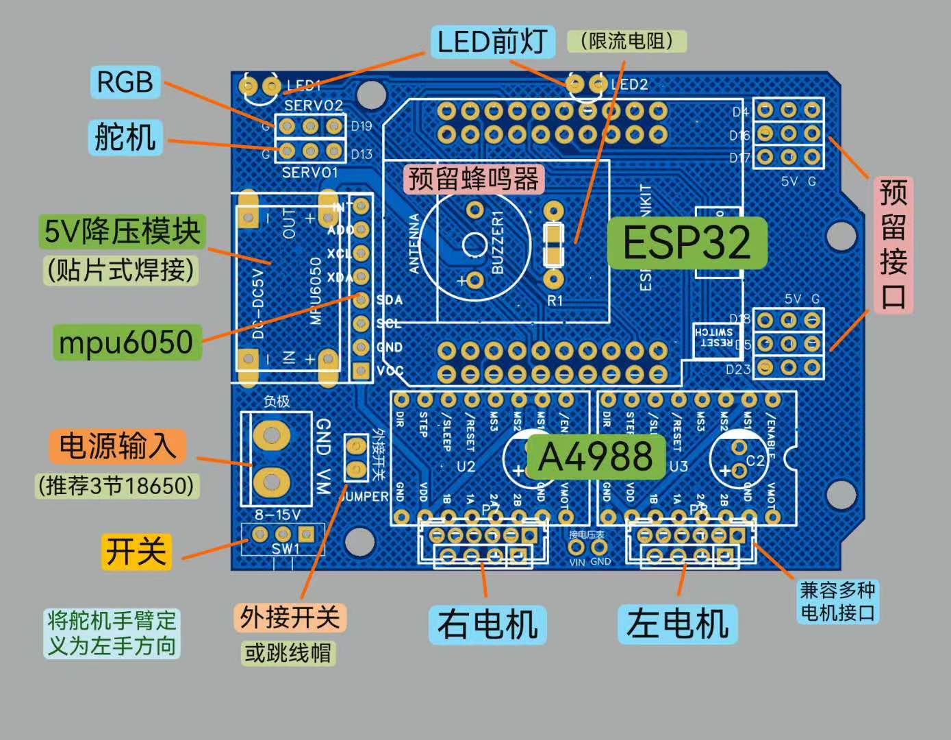
As you can see, the V2 version has some extra interfaces. The motor interface can use 4-pin connectors or headers with a 2.54mm pitch, or 4-pin or 6-pin connectors with a 2.0mm pitch, to accommodate various common stepper motors. Solder the appropriate connectors or headers according to your connector type.
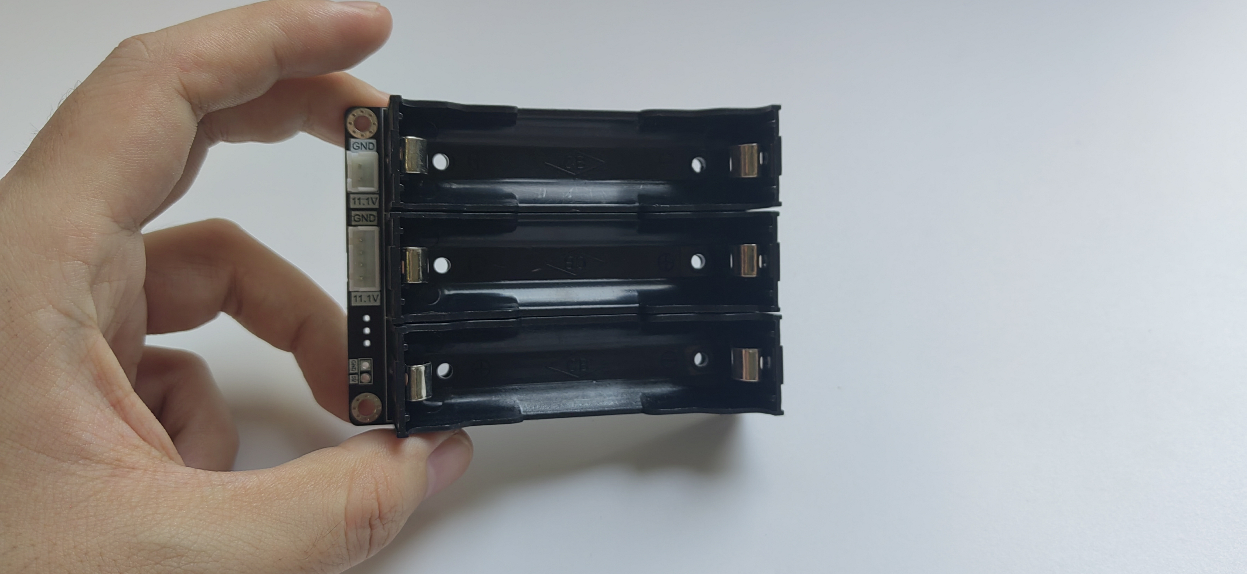
The simple battery box PCB has two XH2.54 interfaces (or headers or female connectors). The 2-pin is for power output, and the 4-pin is for the balanced charger. Be sure to connect the positive and negative terminals correctly to prevent reverse connection or short circuit.
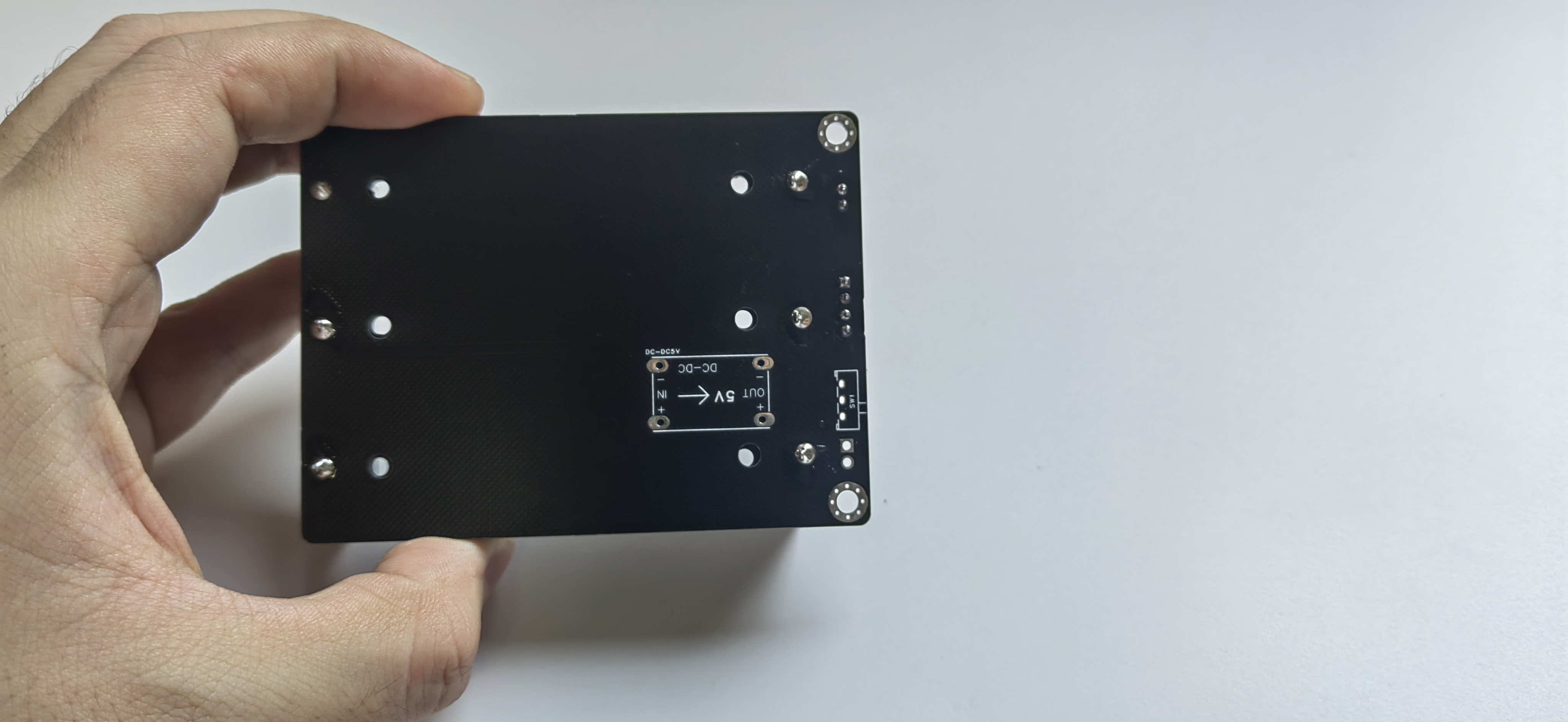
The back of the battery box has a reserved space for a 5V step-down module and a small switch; soldering these on will provide an additional 5V output power.
Of course, a regular 3-cell series 18650 battery box can also be used. You can modify the battery box by adding a 4-pin plug to connect a balance charger.
You can refer to my video on modifying a 2S battery box: https://www.bilibili.com/video/BV1VY411n7r1/?spm_id_from=333.999.0.0 The overall appearance of
the vehicle structure
is basically the same as the original author. I have also compiled several versions of the open-source vehicle body in the resource package, including various servo arm shapes, such as hammers and axes, which you can choose freely.
Because the axles of the wheels in the original author's and other versions are fixed holes, the motor is either too tight to install or too loose to slip. Even if it works during installation, it will slip after a while.
Therefore, I redesigned several types of wheels with a fastening function, similar to couplings, and selected the most suitable version after testing.
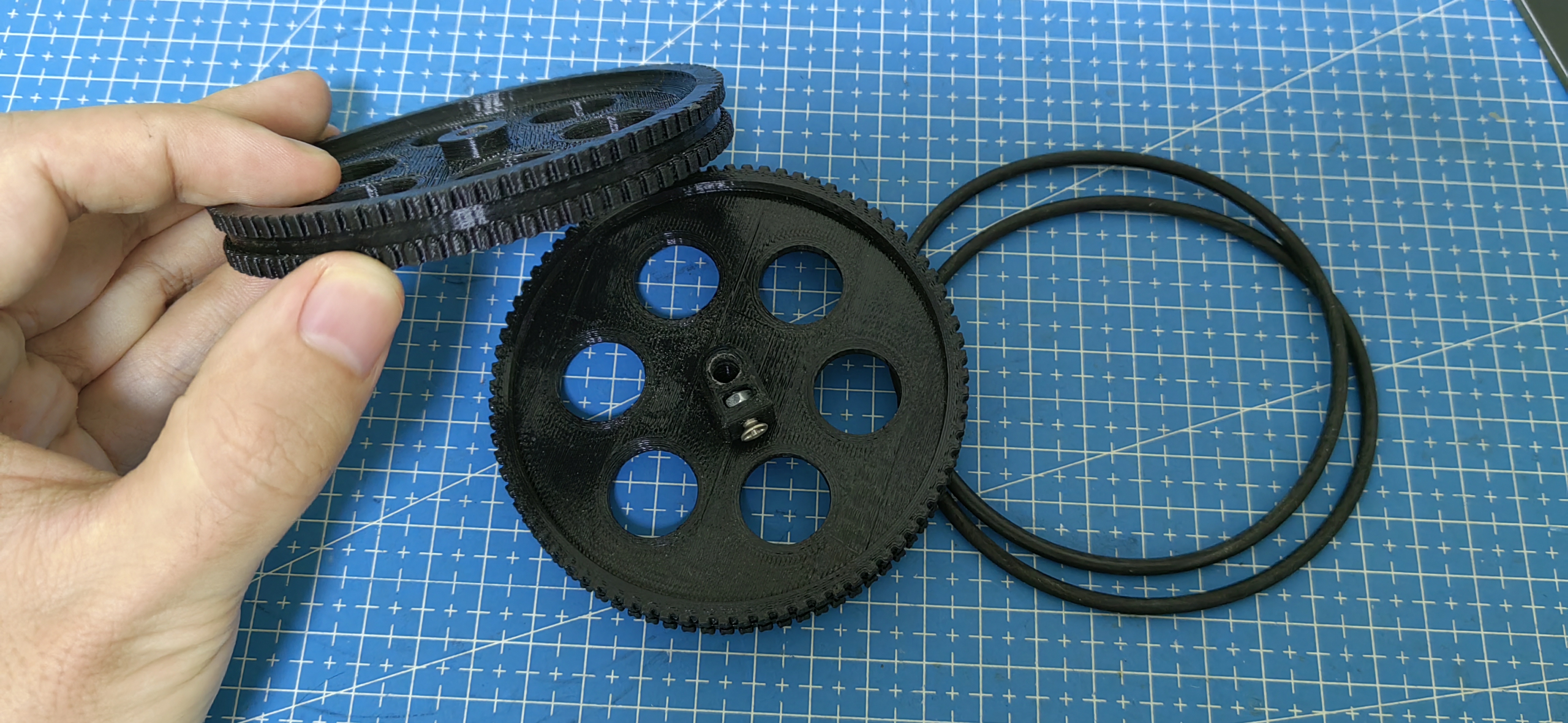
The construction is relatively simple: print it out, clean the support, install M3 screws and nuts, and install O-rings for both anti-slip and quiet operation.
The LED rings on both sides of the wheels are directly fixed with hot melt glue.
Other modifications, such as battery space, servo position, and switch position, will not be detailed here. The V2 PCB has a pre-installed pad for a voltmeter, allowing real-time monitoring of the battery voltage to prevent over-discharge. Those interested can try adding another voltmeter mounting point on the top or side plate. The original B-ROBOT
program and control
uses a Wi-Fi control method with an app; this modified version also supports this method. I added RGB effects to the program. I demonstrated this in a previous video: https://www.bilibili.com/video/BV13Y411c7JL/?spm_id_from=333.999.0.0

However, I prefer using my self-designed ESP-NOW remote control, which also supports my favorite Bluetooth app, so I rewrote the program. The main PID control part is the same as the open-source program (actually, I lack the skill to rewrite it), with added RGB effects and modified control methods to suit my preferences. You can watch this video demonstration: https://www.bilibili.com/video/BV17c411Z7N3/?spm_id_from=333.999.0.0
Both the remote control and the app have switches to toggle between normal (slow) and advanced (fast) modes. The app supports gyroscope motion control. Both left and right joysticks can be used for full-proportional differential control, resulting in smooth movements. The controls from both joysticks can also be combined, which can be understood as having four speed levels: single joystick control in slow mode, combined control with both joysticks, single joystick control in fast mode, and combined control with both joysticks.
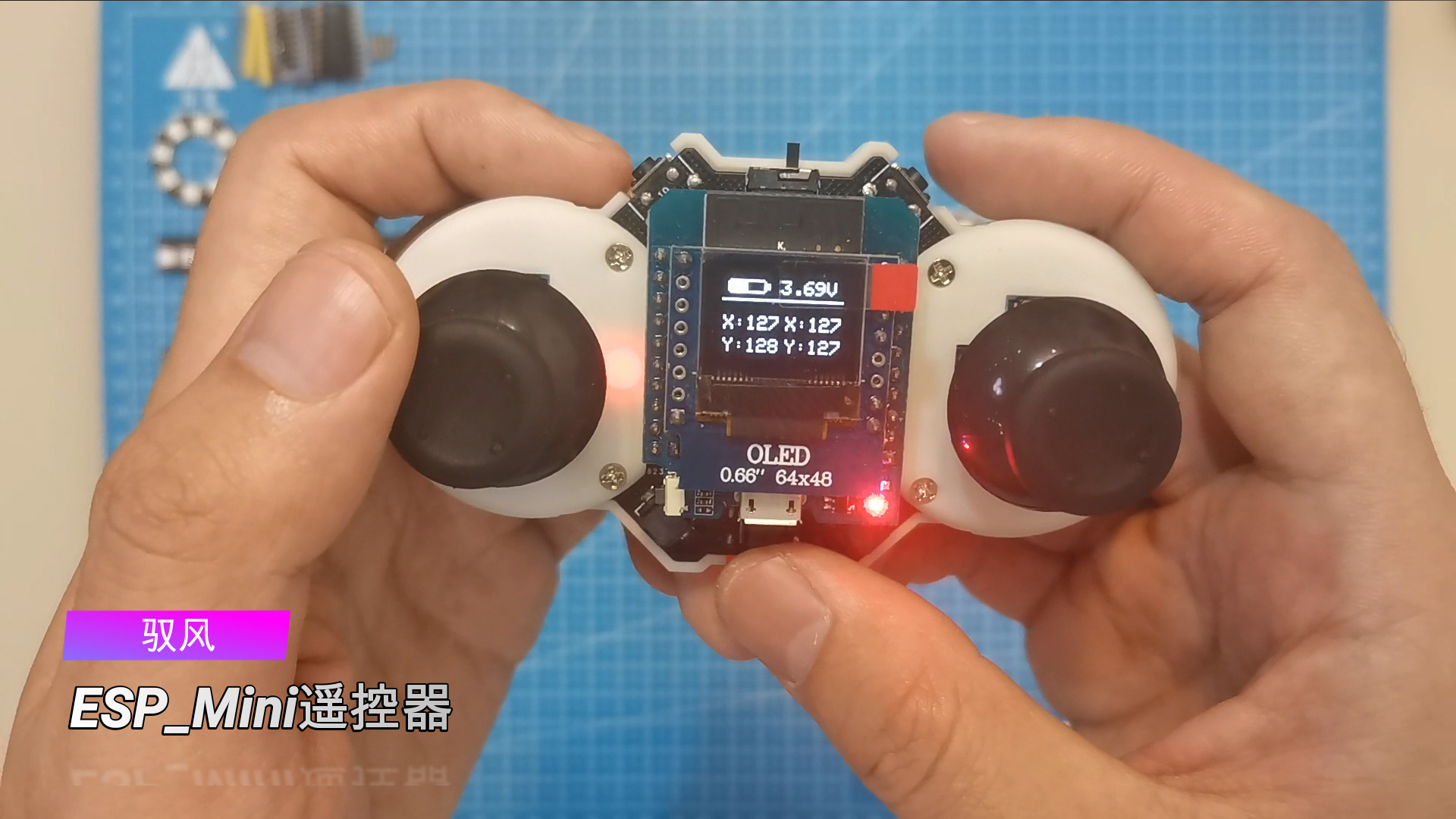
The video demonstrates the use of various remote controls. You can also use my open-source Yufeng ESP_Mini remote control basic version. Those interested can learn to make one: Yufeng ESP_Mini Remote Control - JLCPCB EDA Open Source Hardware Platform (oshwhub.com)
Remote Control Function Demonstration Video: https://www.bilibili.com/video/BV1nT4y1q7AD/?spm_id_from=333.999.0.0
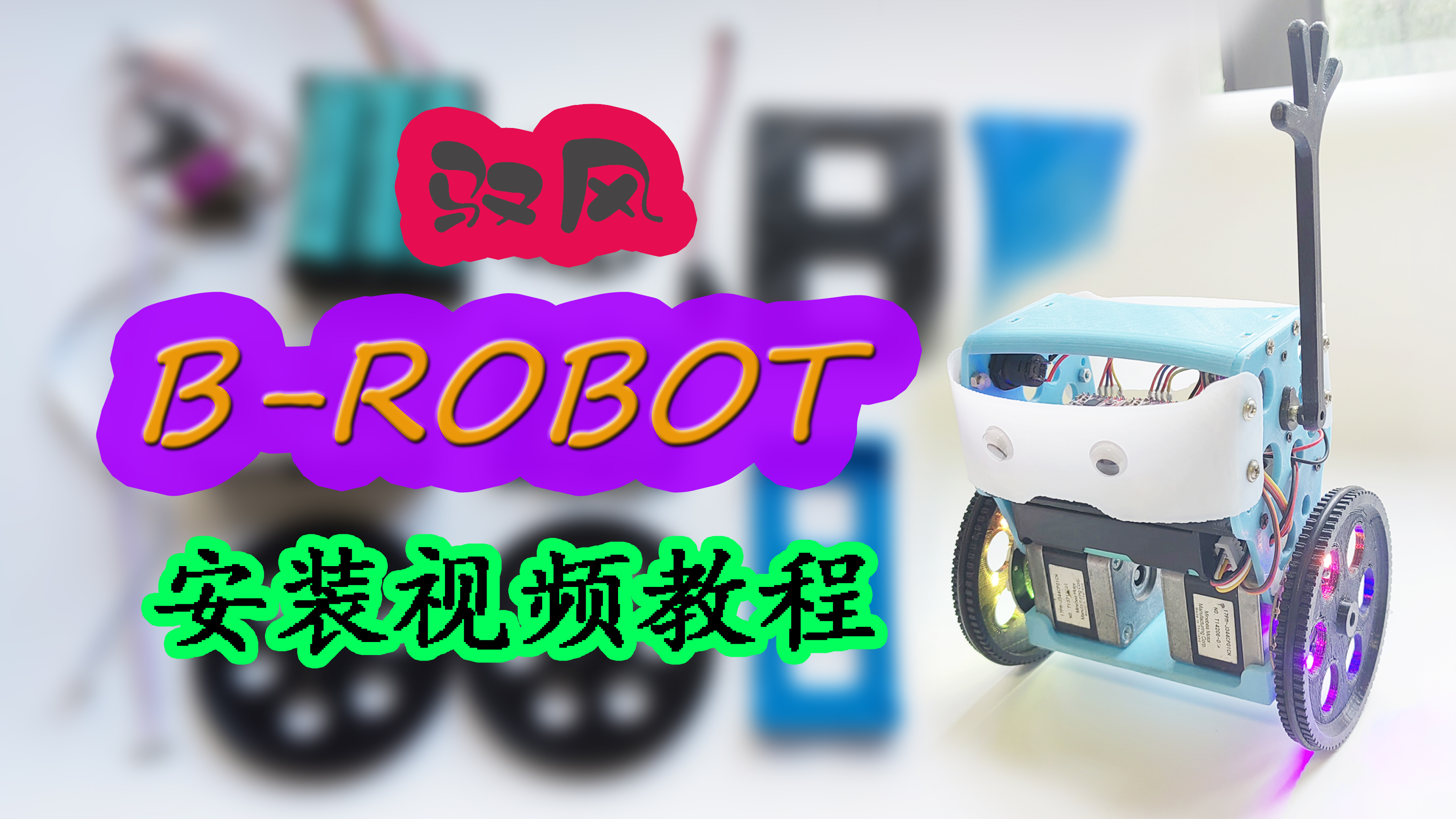
Installation Process
Video Tutorial: https://www.bilibili.com/video/BV1WC4y1n71m/?spm_id_from=333.999.0.0
Note: Do not overtighten the locking screws on the wheel-mounted coupling to avoid damage; just tighten them until they don't slip.
Important Notes: Ensure the positive and negative terminals of the battery box are not reversed during soldering. Prevent short circuits during installation. For the 4PXH2.54 double-ended plug between the balance charger and the battery box, ensure the positive and negative terminals are aligned. If the plug orientation is incorrect, adjust the wiring sequence on the plug .
For materials, use
a modular PCB. The main component materials are listed below. Other components such as pin headers, sockets, small switches, LED resistors, connectors, wires, and battery boxes are not listed individually. I personally use three 2000mAh 5C power-type 18650 batteries.
Control board materials:
Balance scooter body materials:
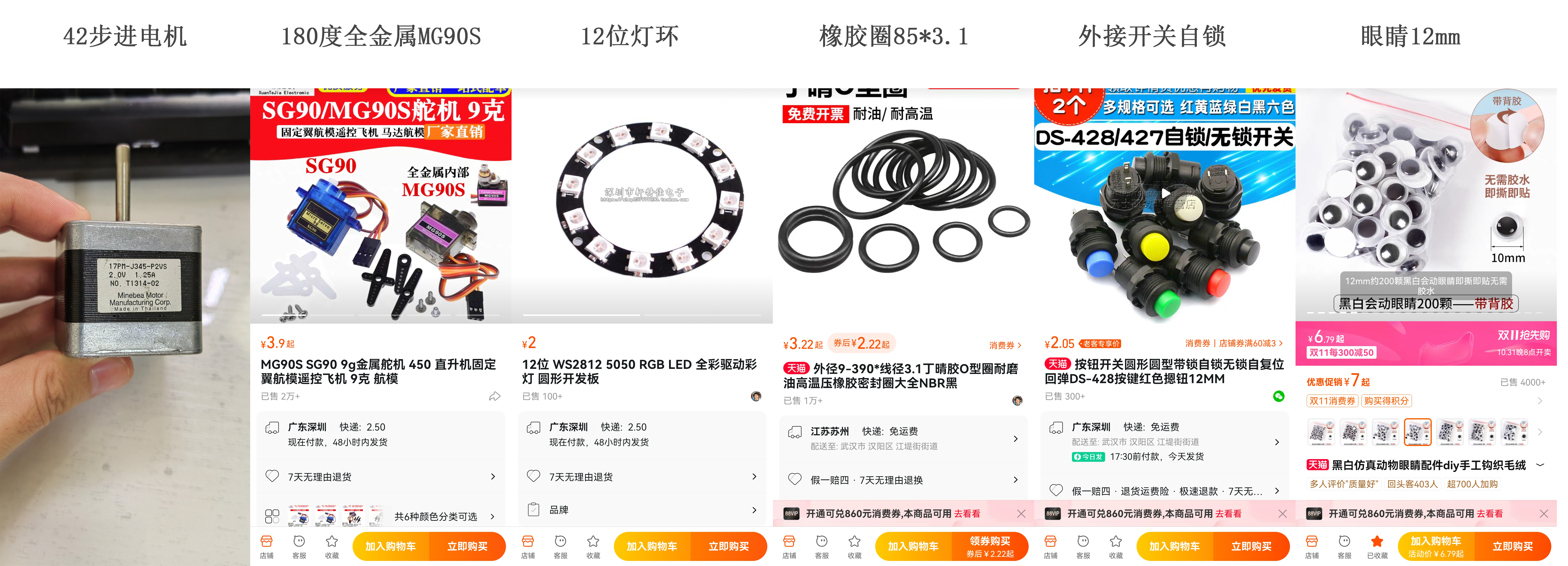
Note: There are many models of 42-stepper motors with different parameters, including two-phase four-wire and two-phase six-wire models. Some motors I've tested work perfectly fine in 3D printers, but vibrate and stop rotating at high speeds when used on a balance scooter. Therefore, I'm providing photos of motors that work correctly for your reference when purchasing.
Also, the wiring may vary between different 42-stepper motors. Those unfamiliar with this can search for 42-stepper motor usage tutorials.

Screws and nuts:
(Buy extra for spares)
Approximately 30 M3*10 nuts (a small number can be replaced with M3*8 nuts, mainly used to secure the vehicle body and motor)
Approximately 20 M3 nuts 2
M2*12 nuts (for securing the servo motor) 2
M2 nuts 4
M3*8 self-tapping screws (for securing the battery box)
2 M2*4 self-tapping screws (for securing the servo arm and hand)
Precautions:
1. Use the all-metal MG90S servo motor for the arm; do not use the ordinary SG90, as it is very prone to vibration. 2. Avoid letting the vehicle stand still for extended periods; testing showed that it will overheat after 20 minutes.
3. If the vehicle is stuck and cannot automatically stand up, do not allow the motor to vibrate without turning for a long time.
4. Prevent children from grabbing the arm, as the servo motor is easily damaged.
5. After installation and testing, it is recommended to use hot melt glue to repair the nuts to prevent them from falling off; using anti-loosening nuts is even better. For beginners learning about
stepper motors and A4988 drivers
, we recommend checking out the tutorials on Taichi Maker:
NEMA Bipolar Stepper Motor (42-step motor) – Taichi Maker (taichi-maker.com)
and A4988 Driver for NEMA Stepper Motor (42-step motor) – Taichi Maker (taichi-maker.com).
Other attachments are also available. The attached
package contains:
"Collected and Organized Open Source Materials for BRobot Balance Cars," which includes several open-source versions of materials and apps; "PCB Materials and Redrawn and Modified 3D Files," which contains my reworked and modified materials; "Simple Car Body Version 3D Files," which contains the printing files for a simplified car body; and "Program and App," which contains my modified new program, featuring both WIFI and Bluetooth/ESPNOW control methods (supporting both Android phone Bluetooth apps and various ESPNOW remote controls I designed).
Additionally: The compressed package contains commonly used serial port drivers. Download and install the Arduino IDE from the official website: https://www.arduino.cc/en/software.
After installing the Arduino IDE, you also need to install the ESP32 environment. The installation method for this is constantly being updated, so it's recommended to search for tutorials yourself.
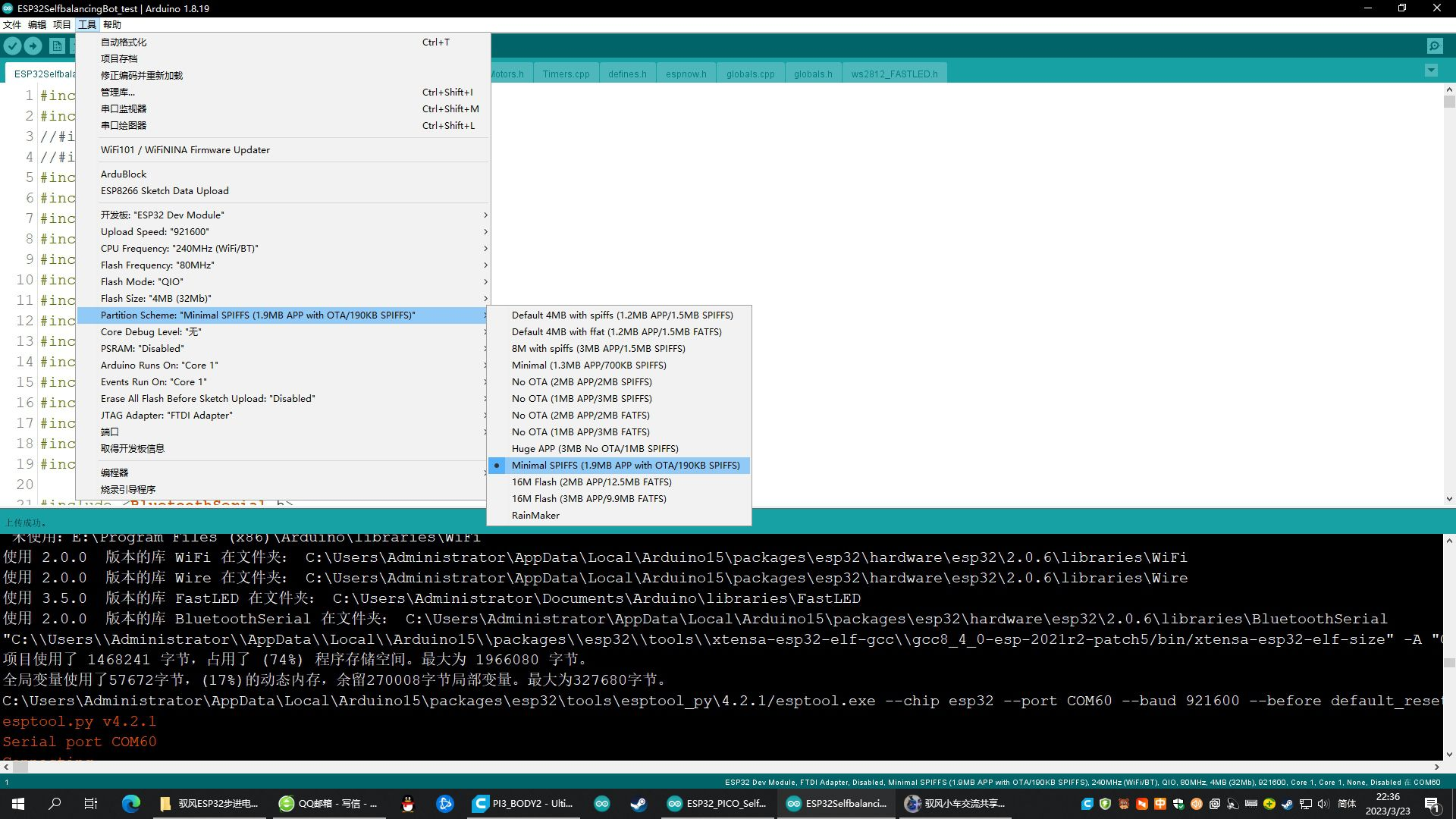
When compiling and uploading programs that communicate via Bluetooth and ESPNOW, the default settings will prompt that the space usage exceeds the limit. Simply select a larger APP space in the upload settings' partition scheme,
such as: Minimal SPIFFS (1.9MB APP with OTA/190k SPIFFS), as shown in the image below.
If you have any questions, you can comment or send a private message under my videos on Bilibili. I don't visit the LCSC Open Source Plaza very often. Join the Yufeng Mini Car Sharing and Exchange QQ group: 922620181, Group 2: 1011789606.


 京公网安备 11010802033920号

 MX1N5989D-1E3


