/************************************************************************************************************/
Update
2023/3/22:
Uploaded the project file "Tri-mode PAD Basic Version.zip". The software used for development is MountRiver. Welcome to create branches to add
features to the PAD or port it to keyboards with different layouts.
2023/3/23:
Updated notes on purchasing components. If you are confused by strange BOM lists, you can take a look.
2023/3/24:
Uploaded the firmware for the keyboard and receiver separately.
2023/3/31:
After testing by group members, the receiver should ideally be 0.8mm thick and green so it can fit into a discarded receiver casing.
2023/7/19:
Thanks to yuan_kj The RGB code added by the expert
has been adapted to the PCB of this project. You only need to burn the "PAD Motherboard RGB Firmware" in the attachment to the keyboard to make it light up.
The latest project compressed package has also been uploaded to the attachment.
2023/8/9:
A few days ago, when writing the code for the tri-mode 61, I found the reason for the frequent Bluetooth disconnections that occurred before. It has been fixed and uploaded to the attachment, "Tri-mode 17RGB (Bluetooth Fix)".
However, the finished keyboard is not with me, and the code has not been verified.
If your keyboard experiences frequent Bluetooth/2.4G disconnections or other malfunctions, you can try using the motherboard firmware in the new project file
.
This is a tri-mode version of the most basic keyboard
(though it lacks touch functionality).
It is perfectly compatible with the basic 17+4's shell and mounting plate, retaining the valuable free shell and mounting plate.
The frame and switch layout are taken from the most basic 17+4TPRO mechanical keyboard - JLCPCB EDA Open Source Hardware Platform (oshwhub.com).
The program is modified from Qinheng's sample program.
Related projects include CH579M Dual-Mode Basic PAD - JLCPCB EDA Open Source Hardware Platform (oshwhub.com).
Function Demo: C3H4O Dynamics - Bilibili (bilibili.com).
Function Description:
The side button is boot. Pressing boot powers on and enters download mode.
boot+/ enters USB mode, with two mode indicator lights lit. Wired connection:
boot+* Entering Bluetooth mode, one mode indicator light will illuminate, indicating the Bluetooth name is 3modekeyboard.
Bluetooth can save four hosts. Another mode indicator light will illuminate. Press boot + 1/2/3/enter to quickly switch between paired hosts.
Press boot + 4/5/6/+ to delete paired host information and enter Bluetooth pairing mode.
boot + - enters 2.4G mode. If it is the first time using it, simply insert the receiver to complete pairing (or press boot + 8 to pair).
Different colored indicator lights indicate the mode, NUMLOCK, charging, and main control power supply status.
The four additional buttons on top are ESC, TAB, PrintScreen, and Backspace
to save the mode at the last power failure.
Soldering and programming precautions:
It is best to use different colored indicator lights (at least three mode indicator lights should be different)
. CH582 is in QFN package. Soldering is relatively difficult, so it is recommended to solder the receiver first. Observe for any bridging or cold solder
joints before soldering other components.
For receiver prototyping, be sure to choose 0.8mm thick, green solder mask (non-green thickness is not free). The software used for programming is Qinheng's WCHISPTool (attached).
After opening the software, press the keyboard boot button and plug it into the computer to enter download mode.
Generally, the first download does not require pressing the boot button, so you can judge whether the soldering is fine by whether it is recognized after power-on.
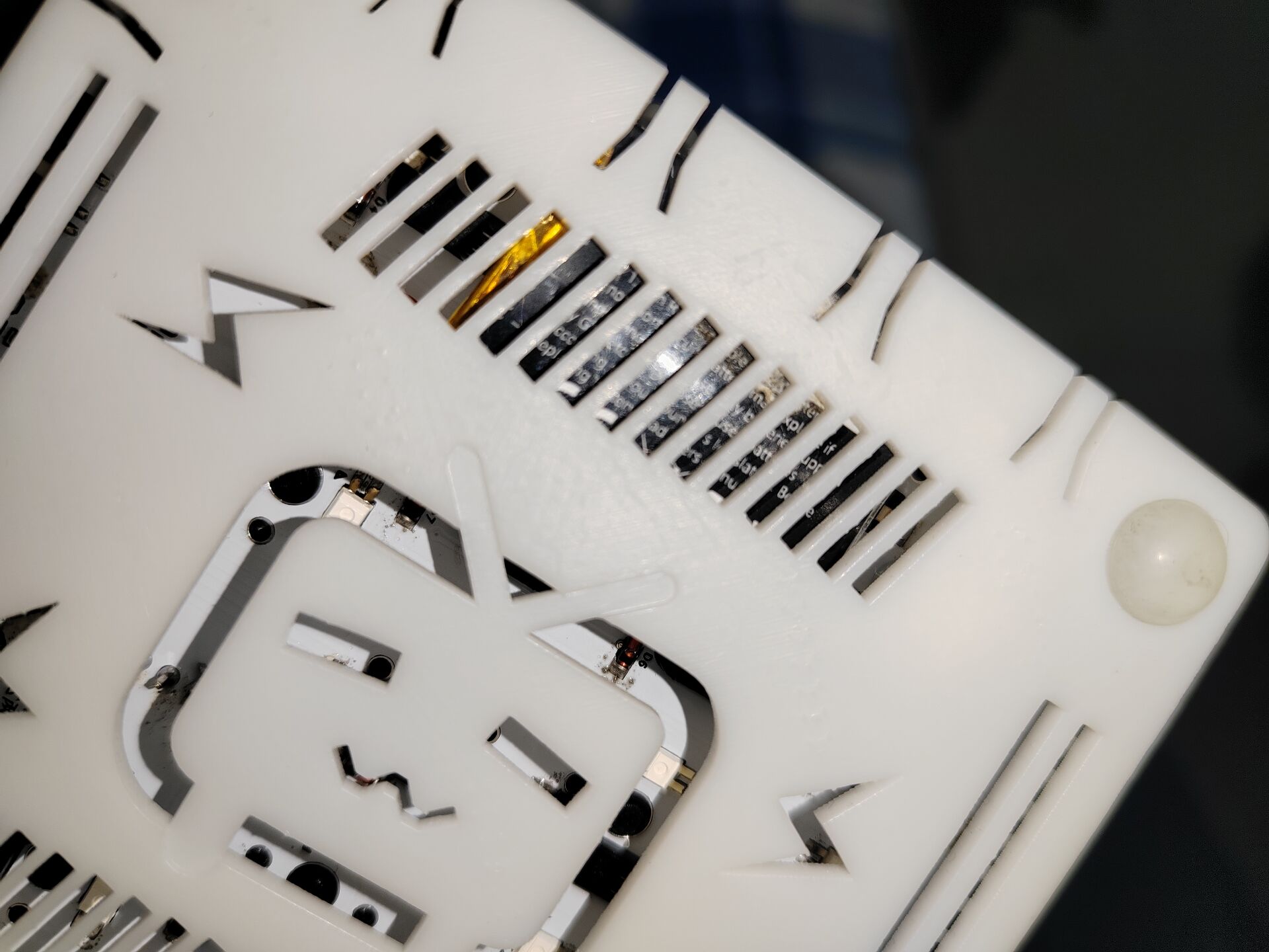
When programming the receiver, be sure to check PB11 as the download configuration pin, as shown in the figure below. When programming the keyboard, be sure to select PB22.
Be sure to distinguish between the keyboard firmware and the receiver firmware!
Component purchasing matters:
Do not purchase according to the automatically generated BOM at the bottom of the webpage! I've silkscreened
the names, packages, and purchase links for most of the important components on the keyboard PCB (links to my purchases are provided):
1. Battery Management Chip: TP4056 SOP8 package
2. High-Speed Crystal Oscillator: 32MHz 3225 package
3. Low-Speed Crystal Oscillator: 32.768KHz 3215 package
4. Voltage Regulator Chip: RT9193-33GB SOT-23-5 package
5. Storage Compartment: Recessed USB Female Connector https://m.tb.cn/h.UqIMYwu?sm=b4ca00?tk=EI0PdQn604S
6. Recessed Tactile Switch: https://m.tb.cn/h.UrUsDE8?sm=f4b7fc?tk=iCZhdQni3p6
7. Toggle Switch: 7-Pin Toggle MSK-12C01-07
Important component names, packages, and purchase links for the receiver PCB (link provided for my purchases): 1.
Crystal oscillator: 32M 2016 package
2. Voltage regulator chip: XC6206P332MR SOT-23 package
For any other components, if unsure, open the PCB editor in the upper right corner and purchase the components listed.
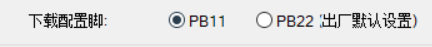
Finished product image:

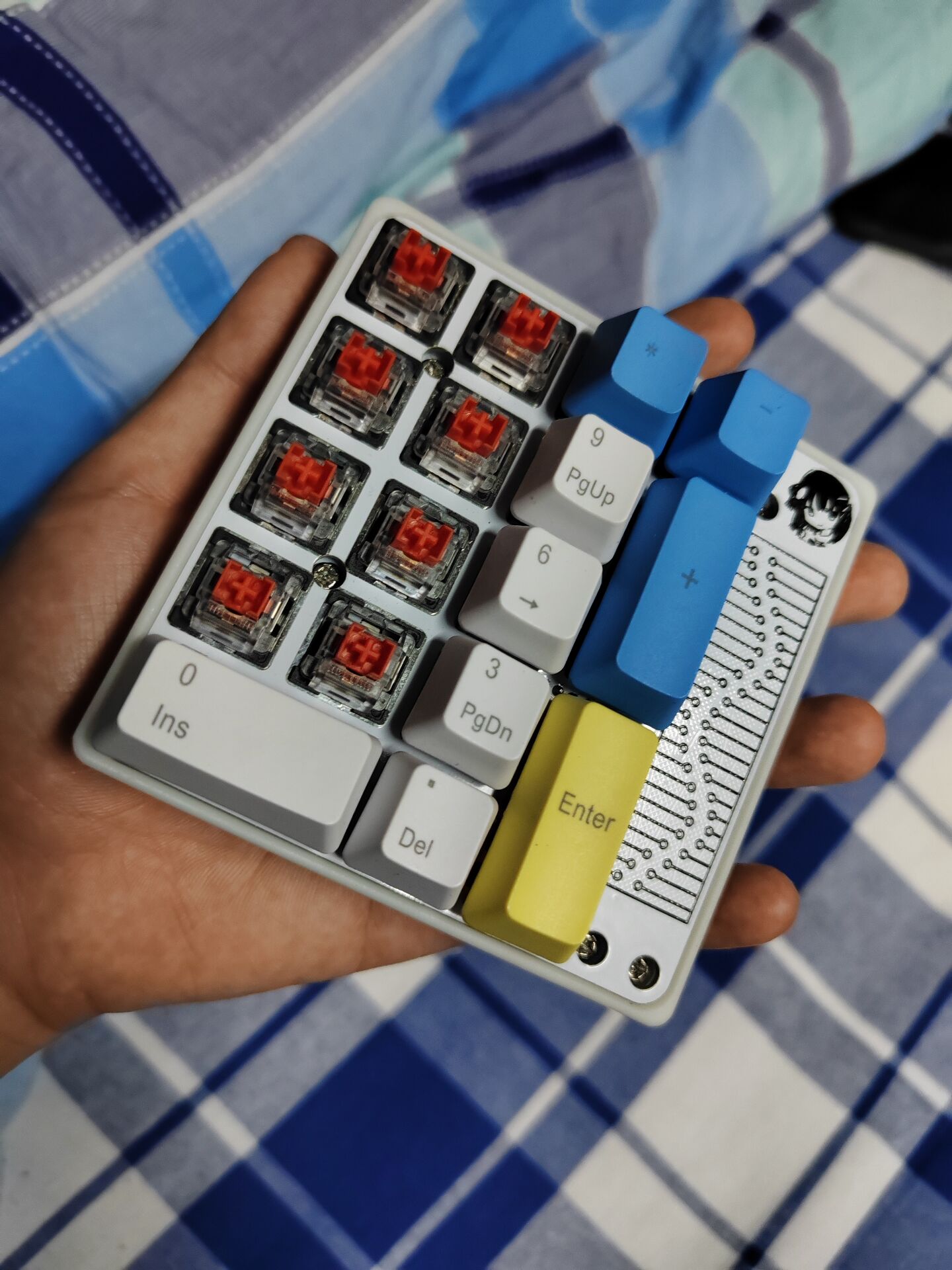
Perfectly compatible with the basic 17+4 casing and positioning board.
The remaining space on the bottom shell can only accommodate a thin battery of about 500mAh.
The receiver is difficult to solder (it's very small and has two surface-mount capacitors on the back).

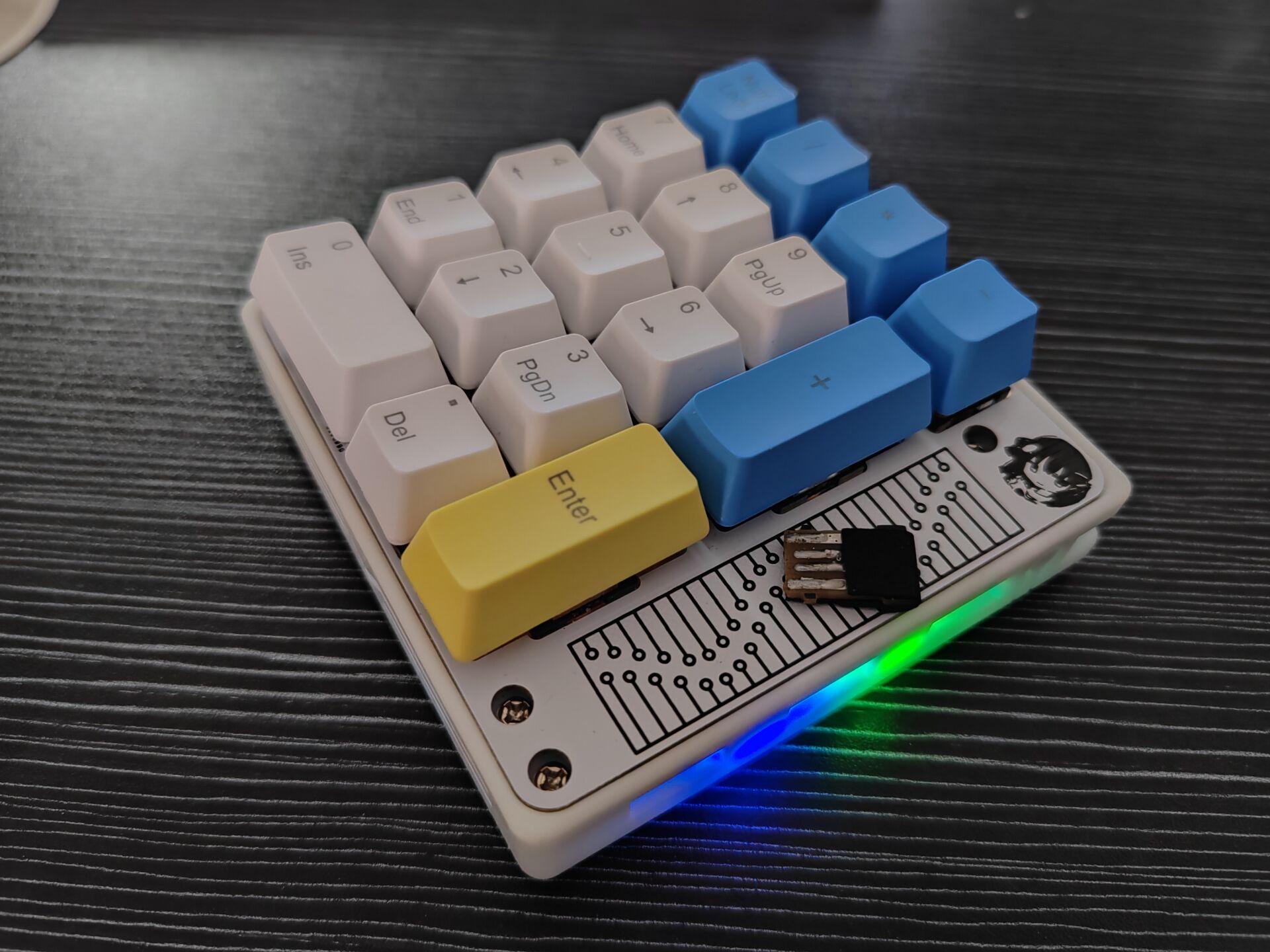
This keyboard is currently just a pure tri-mode PAD
, but the hardware has reserved a touch area, which may be added in a future update (creating a new folder).
Looking forward to help from experts!


 京公网安备 11010802033920号

 NTE2062


