I. Project Introduction
This project uses domestically produced chips, specifically the GD32F303CBT6 from GigaDevice, as the main control chip. It is powered by a Type-C interface and incorporates a lithium battery charging and discharging circuit as well as a power switching circuit to ensure portability. It uses a VL53L0x laser measurement sensor, which can achieve accurate measurements within 2 meters. Measurements are triggered by a button, the measurement data is displayed on an OLED screen, and a buzzer provides a reminder.
II. Onboard Resources
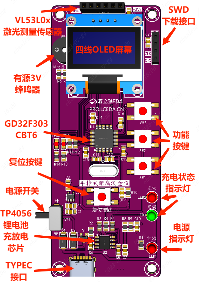
: Main Control Chip: GD32F303CBT6;
Power Interface: TYPE-C 6Pin;
Display Interface: 4-wire OLED display interface, battery charging indicator LED, power indicator;
Boot Mode: BOOT mode configuration, resistance soldering;
Debugging Interface: SWD programming method, 4Pin through-hole header;
Peripheral Interfaces: 3V active buzzer, VL53L0x laser measurement sensor 4Pin interface;
III. Advantages and Features:

The board has a slender appearance, making it easy to hold with one hand, with dimensions of 40mm*99mm (1574.803mil*3897.638mil);
The overall layout is not compact, making it easy to solder;
The chips and sensors are inexpensive, feature-rich, and cost-effective;
It uses high-quality PCBs and genuine components from JLCPCB to ensure product quality;
IV. Circuit
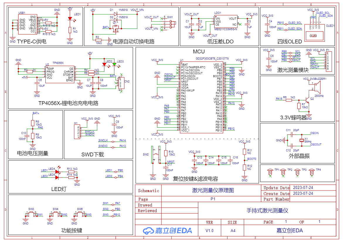
Diagram 4-1 Handheld Distance Measuring Instrument Schematic Diagram
1. Power Supply Circuit The power
supply circuit mainly consists of a TYPE-C power supply circuit, a power switching circuit, and an LDO-5V to 3.3V converter. It uses a 6-pin TYPE-C interface, which is simple, convenient, and easy to solder.

Figure 4-2 shows the TYPE-C power supply circuit
. The LDO-5V to 3.3V step-down circuit takes power from the TYPE-C interface or battery, steps it down to 3.3V, and supplies power to the main control chip. The capacitor acts as a filter to make the output voltage signal more stable.
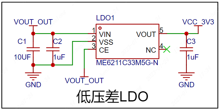
Figure 4-3 shows the LDO-5V to 3.3V
converter circuit. The power switching circuit uses an AO34001 Amos transistor and a 1N5819 Schottky diode to form a power switching circuit, thereby realizing fast switching between the TYPE-C interface and the lithium battery.
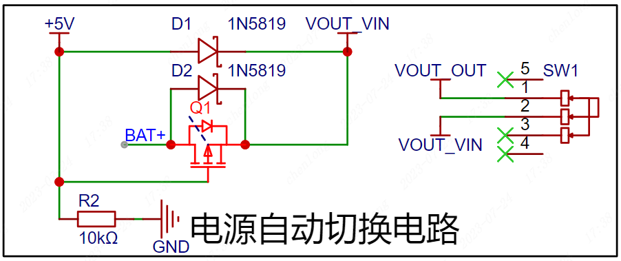
Figure 4-4 Automatic Power Switching Circuit
2. Main Control Circuit
The GD32F303CBT6 uses a Cotrx-M4 core with a 120MHz main frequency, 128K Flash, and 32K RAM. The capacitors here are for filtering and should be placed as close as possible to the chip pins when designing the PCB. A resistor controls the BOOT0 pin to control the startup mode. Note that the BOOT pin cannot be floating; a low level on the chip initiates a reset. SW2 is the reset button; when the button is pressed, the reset pin is pulled low to initiate a reset.

Figure 4-5 GD32F303CBT6 Main Control Circuit
3. Crystal Oscillator
Circuit The crystal oscillator provides the clock signal to the main control chip. The capacitors beside the crystal oscillator ensure a more stable output oscillation frequency. The 8MHz crystal oscillator circuit provides the clock signal to the microcontroller.
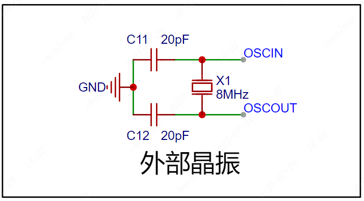
Figure 4-6 Crystal Oscillator Circuit
4. Sensor Circuit
A four-wire OLED screen is used to display measurement data. The module itself has pull-up resistors, so the IIC interface does not require external connections.

Figure 4-7 shows the four-line OLED screen circuit,
which uses a VL53L0x laser sensor module for laser ranging. The module uses IIC communication and has two control pins, compatible with 3.3V and 5V levels.

Figure 4-8 shows the laser measurement circuit
, which uses a passive buzzer for measurement indication. An NPN transistor drives the buzzer, R6 is the base current limiting resistor, and R7 is used for rapid shutdown and to prevent abnormal buzzer noise caused by power-on level instability.
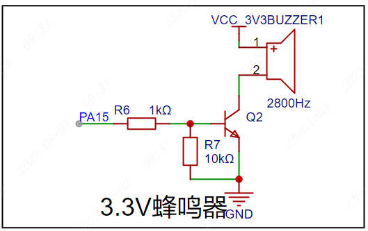
Figure 4-9 shows the passive buzzer circuit
. 5. The lithium battery charging circuit
uses a TP4056X single-cell lithium battery charging and discharging chip to charge the lithium battery. LED2 is the charging indicator, and LED3 is the charging complete indicator. The charging current is modified by changing the resistance value of R3.
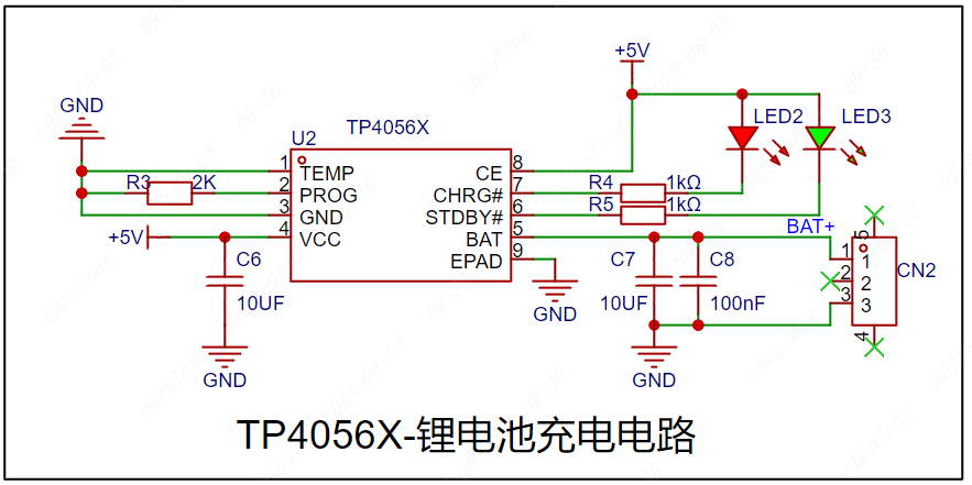
Figure 4-10 shows the lithium battery charging circuit .
The microcontroller ADC supports a maximum sampling of 3.3V. Resistor voltage division is used to convert the battery voltage to the normal range to determine the remaining battery power.
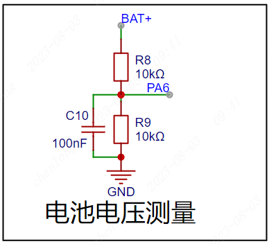
Figure 4-11 shows the battery voltage measurement circuit.
6. The basic peripheral circuit
uses LEDs to test the microcontroller's I/O output function and also as status indicators.

Figure 4-12 shows the LED circuit,
which uses a button to test the microcontroller's I/O input function and can also be used as a start measurement status input.

Figure 4-13 shows the button circuit.
6. The download circuit
uses SWD download, and the download pins are brought out through a 2.54*4P female connector for easy connection to an external downloader.
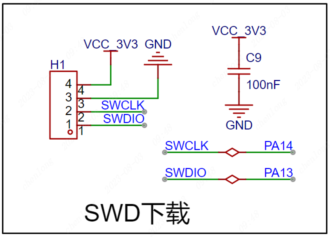
Figure 4-14 SWD Download Circuit
V. PCB Layout Recommendations
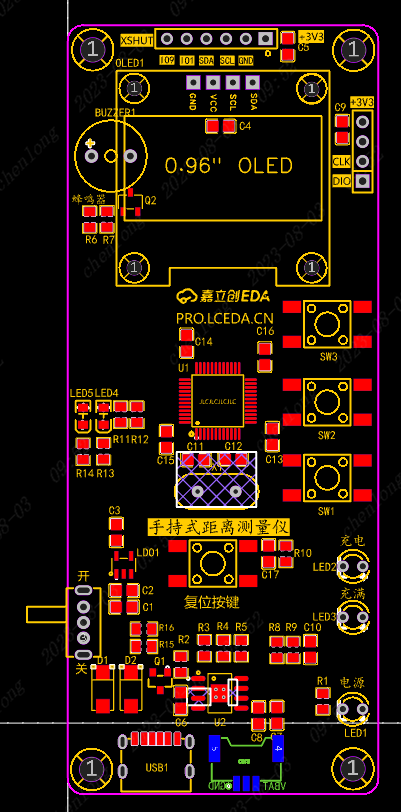
Figure 5-1 PCB Layout Reference:
Power supply traces are set to 30mil, signal traces to 10mil;
Components should be placed on the top layer as much as possible,
and battery interfaces should be placed on the bottom layer. Top layer routing should be the primary method, and through-holes can be used to switch to the bottom layer for connection;
Straight lines should be prioritized during routing, and bends should be made with 135° obtuse angles or arcs, keeping the horizontal and vertical lines straight and maintaining a neat design;
Crystal oscillator traces should be kept as short as possible, and no traces should be run at the bottom to reduce noise interference;
GND fan holes should be appropriately placed during routing to avoid incomplete GND after copper pouring;
VI. PCB Layout Recommendations

Figure 6-1 Top Layer Copper
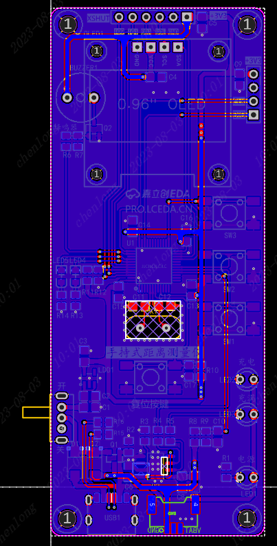
Pour Diagram Figure 6-2 Bottom Layer Copper
Pour Diagram Mark and label board information (handheld distance measuring instrument);
Add silkscreen markings for buttons, external pins, and debugging interface functions;
Add a teardrop effect to the completed PCB design to make the board more aesthetically pleasing and stable;
Add JLCJLCJLCJLC under the components to specify the customer coding position for a neat board finish;
VII. Component Soldering
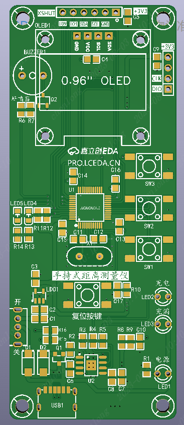
Figure 7-1 The recommended order for soldering auxiliary tools is
as follows:
First, solder the TYPEC interface, ensuring there is no short circuit in the power supply .
Then, solder the chip, ensuring the pins are soldered correctly and there are no solder bridging or cold solder joints . Next,
solder the resistors, capacitors, diodes, chips, and crystal
oscillators. Finally, solder the switches and connector pins.
Note:
When soldering, you can select the soldering auxiliary tools in the JLCPCB EDA toolbar for real-time interaction and convenient soldering.
After soldering, clean the surface with alcohol or board cleaner, and carefully inspect the chips and interfaces for any problems;
VIII. Physical Demonstration
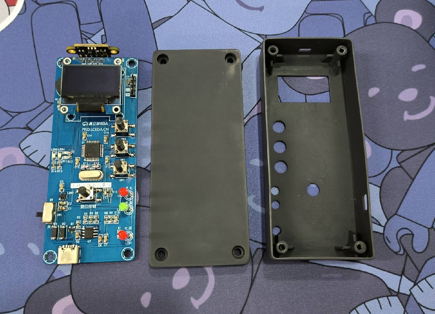
Figure 8-1 PCB Board and Housing
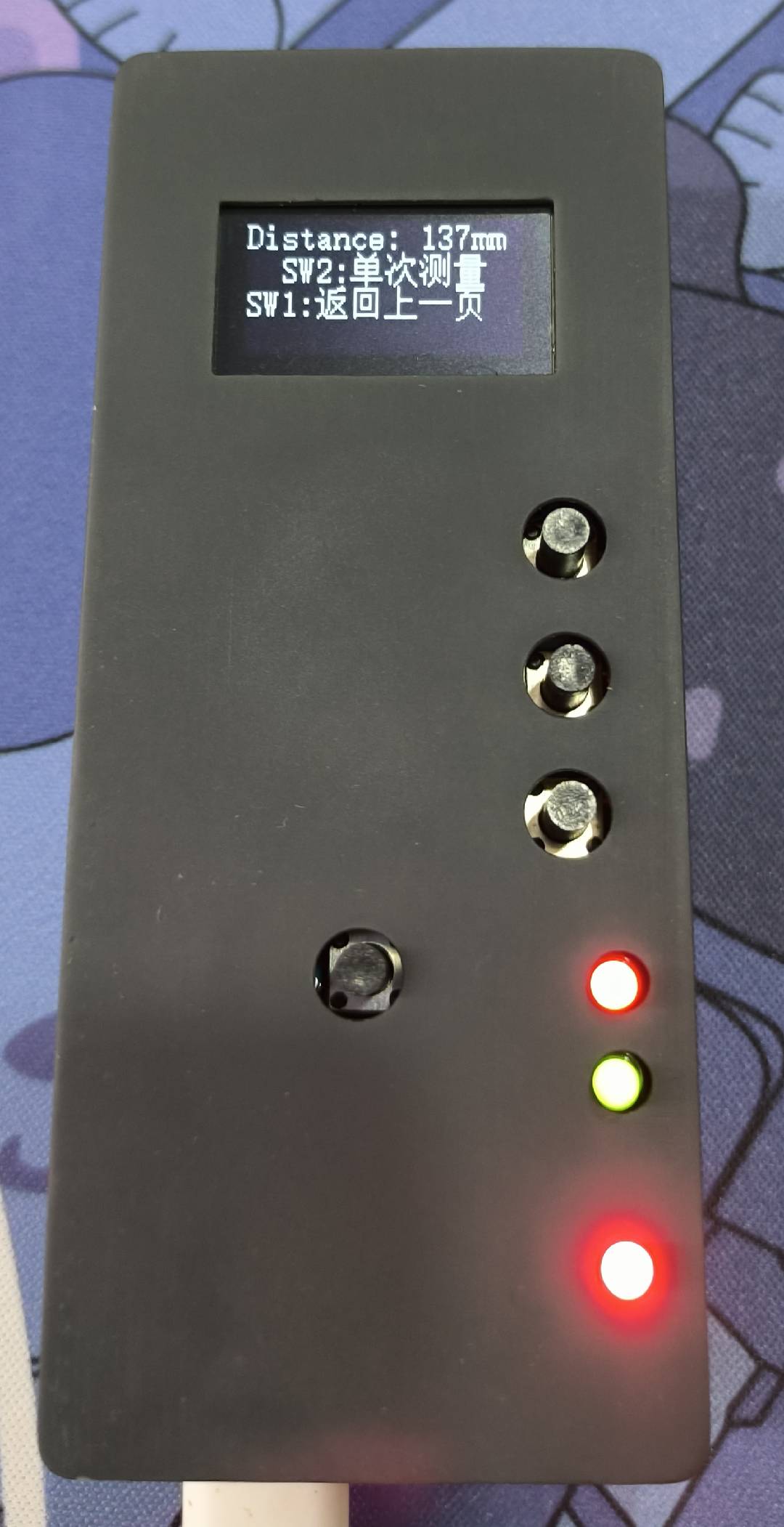
Figure 8-2 Actual Result


 京公网安备 11010802033920号

 RS5RJ3329A


