I. Project Introduction
I've been following the training camp for a long time, and each one has made me eager to participate, but I haven't been able to due to various commitments. As a beginner, this is my first official training camp, and I want to experience the entire DIY design process firsthand.
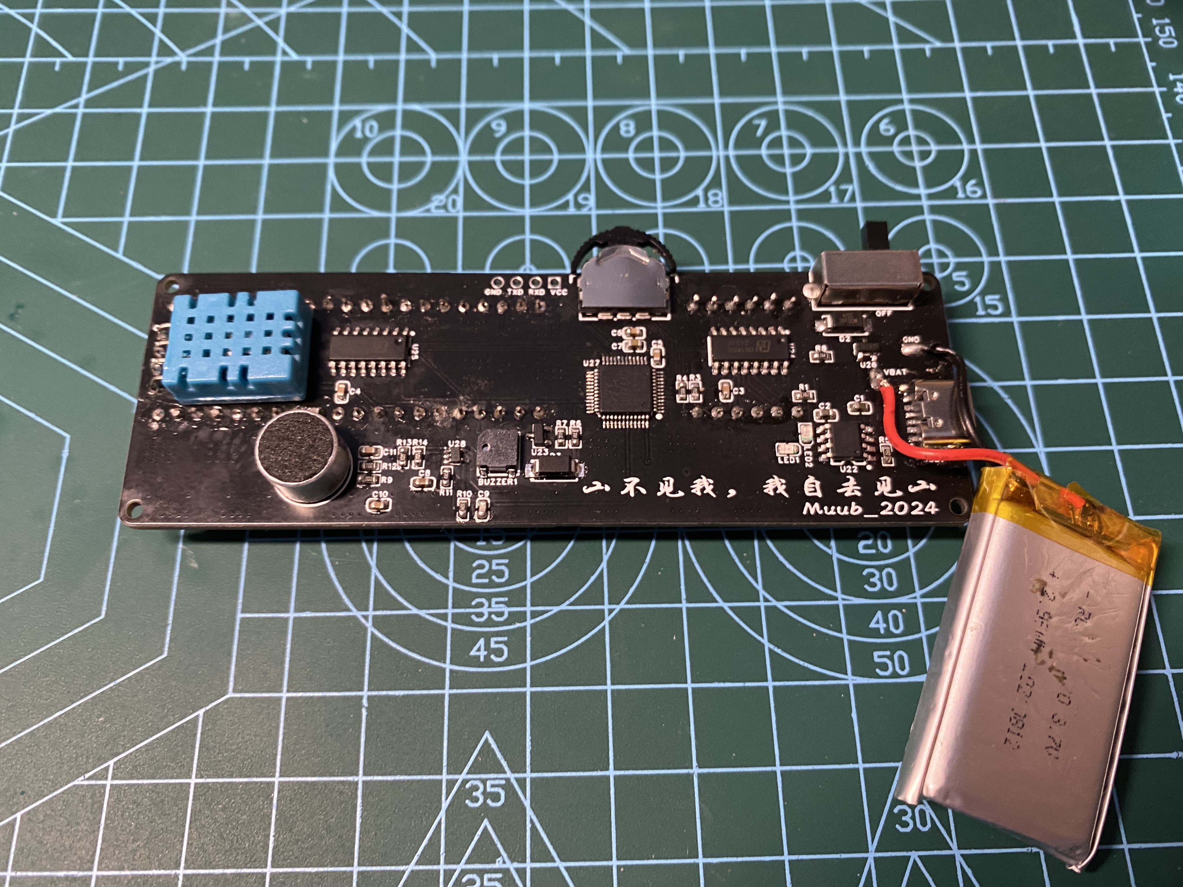
This project combines my knowledge with existing electronic components to create a desktop rhythmic clock based on the STC8H8K64U. It will feature functions such as time and date display, temperature and humidity monitoring, a timer, countdown timer, alarm clock, and rhythmic light strip.
[3] Three-legged dial switch controls the interface through single click, double click, long press and other operations
[6] Uses classic TP4056 for lithium battery charging, can be powered by USB or lithium battery
[7] 1 serial port can be used for program download and time synchronization and other communication
II. Hardware
The schematic diagram drawn by a novice is not worthy of explaining the hardware principle. It is just some typical charging, acquisition and minimum system circuits. Many design problems were found in the process of making the physical object (which will need to be modified in future versions):
[2] It is recommended to use a higher version of the web version of EDA for DRC check to avoid incomplete checks by the lower version
[3] The connection of the S and D terminals of P-MOS in the power switching circuit is incorrect (although the power switching can be performed normally, the battery voltage is too low, which will cause the voltage to be unable to be pulled up to 5V when charging).
[4] The current-limiting resistor for the indicator light in the charging management circuit is too small, causing the charging LED to be too bright and affecting the appearance of the actual product (it is recommended to replace R1 with a resistor of about 3.6K).
[5] Since there is a clock function in the design, an external 32.768KHz crystal oscillator should be connected to reduce the time error.
[6] Since it is necessary to synchronize the time with the host computer to set the alarm, a 12P-TYPE-C should be used and a serial port chip should be added to directly complete the charging and time synchronization functions with a single data cable. III. PCB part
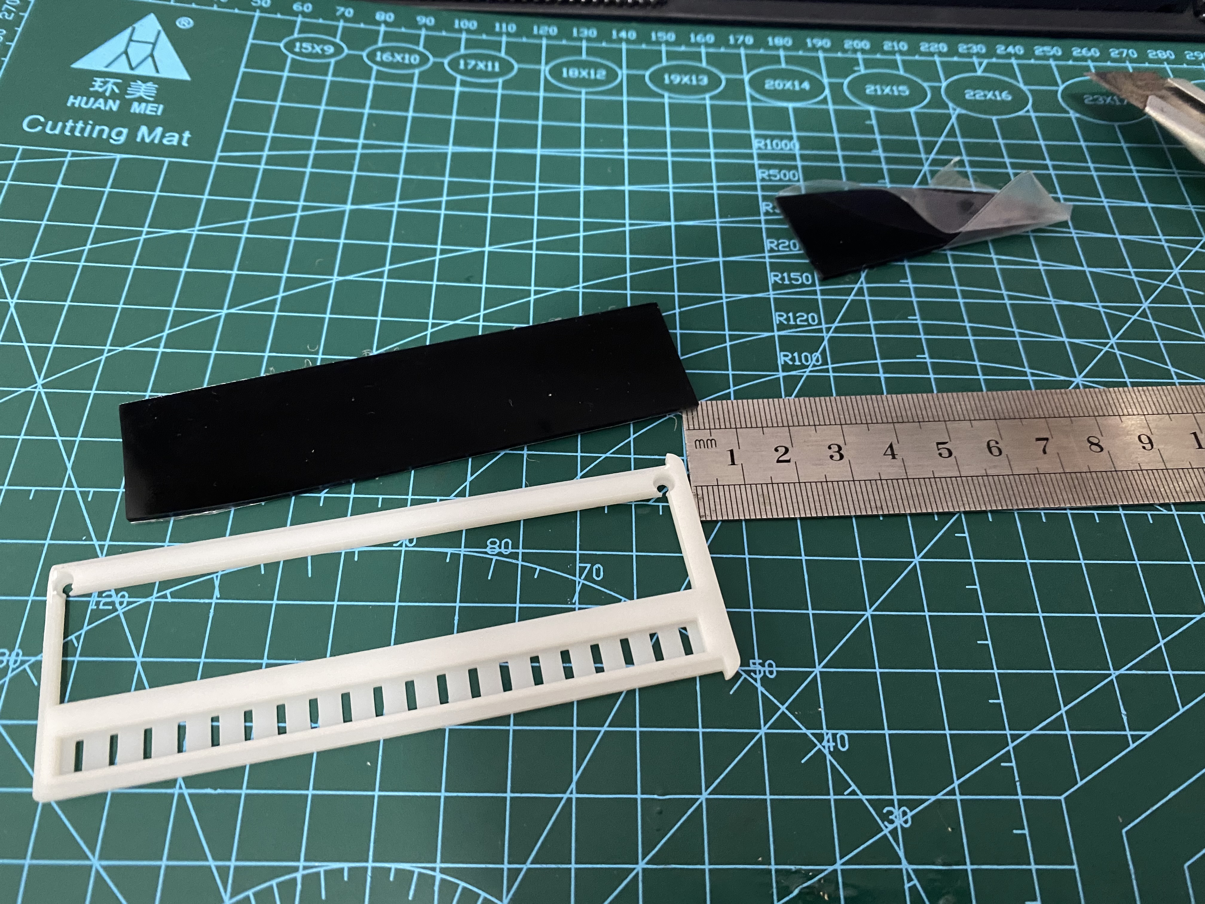
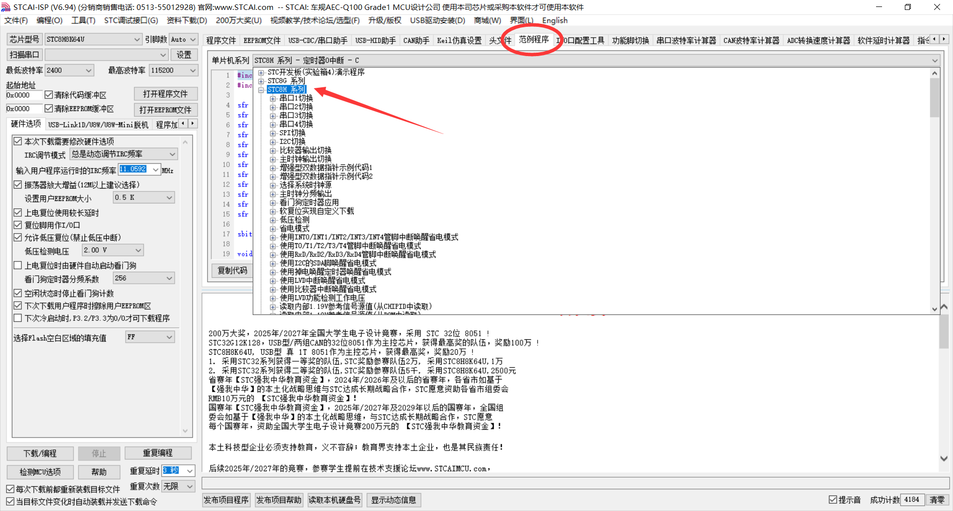
of the actual product : 1. Soldering sequence: Solder the surface mount components first, then the through-hole components. 2. The surface mount components can be soldered one section at a time, testing each component for correct soldering. 3. For chips with densely packed pins, use a magnifying glass to check for solder bridging. 4. For through-hole components, solder the toggle switch first, then the digital tube sensor, to prevent densely packed components from being impossible to solder. 5. After successful testing, solder the battery casing: Use a 1.5mm thick dark brown transparent acrylic sheet as a light-blocking sheet . 1. To save costs, cut a suitable area from a large acrylic sheet. 2. Using a utility knife and file for polishing is too much work; it is recommended to use a grinder for direct cutting. 3. The 3D printed casing uses a push-to-open design; errors in the screw hole positions on the upper and lower casings require polishing with a file. IV. Software: The program interface is mainly divided into eight interfaces, which can be switched and data modified by using a dial switch. Upon power-on initialization, the chip ID information is read and sent to the host computer, then the remaining battery power is checked ("2050/4096"), and finally, peripheral ports are initialized, with the progress bar gradually filling in. enum{ date_dis=0,time_dis,temp_dis,clock_dis,power_dis,text_dis,timer_dis,cntdown_dis }mode=1;//Display flags 0->Date display 1->Time display 2->Temperature and humidity display 3->Alarm clock display 4->Battery power display 5->Text lights 6->Timer 7->Countdown 1. Time display interface: "13-23-50" displays hour, minute, and second data. Switch between interfaces using the left and right dials. Press the dial to set the time; the corresponding data will flash as an indicator. Adjust the time data by single or double clicks. If no adjustment is made within two seconds, the adjustment interface will automatically exit. 2. Date display interface: "2024.07.09" displays year, month, and day data. The range of years from 2000 to 2099 can be adjusted, similar to date adjustment. 3. Temperature and humidity display interface: "T.32℃ H.60" displays temperature and humidity respectively. In this interface, long press the dial switch to adjust the brightness of the digital tube in 8 levels. 4. Alarm Clock Display Interface: "00:00 1" displays the alarm time on the left and the alarm switch on the right. A buzzer sounds when the alarm time is reached. A single click on the dial adjusts the alarm, and the corresponding data flashes. If no adjustment is made within two seconds, the adjustment mode is exited. 5. Battery Display Interface: "18352055" displays the noise and battery levels detected by the ADC, respectively. The maximum value for the 12-bit ADC sampling is 4096. 6. Color-Changing Lights: Turns off the digital display and displays colorful lights (customizable light patterns are available later). (6.1 Text Lights: The initial plan was to use a clock-swinging motion to quickly change the brightness of the lights, creating a brief visual display of text or patterns.) 7. Timer Display Interface: "00.00.00.00" represents hours, minutes, seconds, and milliseconds, with a maximum precision of 0.01ms. A single click starts the timer, and a second click stops it. A long press stops the timer and resets the timer to zero. 8. Countdown Display Interface: "-00.00.10--" represent hours, minutes, and seconds respectively. A single click on the button starts and stops the countdown. A long press enters the countdown timer modification interface. Adjust the data by moving the dial left and right. After entering modification mode, clicking the button again switches between data modification modes. If there is no operation for a period of time, it automatically exits modification mode. A buzzer sounds when the countdown reaches zero. 9. Rhythmic LEDs: In addition to changing LED modes, the system continuously collects sound from the MAX4466 microphone and converts it into a rhythmic LED display. Some experiences were summarized during software programming: 1. A chip can be quickly mastered using the STCAI-ISP and official examples in the chip manual. Solutions to similar problems regarding chip design and programming can be found on the STC official forum. 2. Quasi-bidirectional ports can directly read temperature and humidity data from DHT11 components. However, DHT11 modules with 4.7K pull-up resistors cannot be read using traditional quasi-bidirectional ports; the I/O port mode must be continuously changed during data reading or transmission. During transmission -> push-pull output: P2M1 &= 0xfe; P2M0 |= 0x01; During reading -> high-impedance input: P2M0 &= 0xfe; P2M1 |= 0x01; Software improvements needed (to be continued after debugging): 1. Change the ADC power acquisition data to a 0-100 percentage display for greater simplicity . 2. In the rhythmic LED display, set an appropriate R10 resistance value to adjust the gain and filter the data for better display of the rhythmic waveform. 3. The excessively high timer interrupt frequency in the button multi-function scan affects the timing of the WS2812 LED display. 4. After power-on initialization, the display and button functions are unstable.
5. Although designed for desktop use and not designed for on-the-go charging, a low-power display function can be added.
V. Program Download
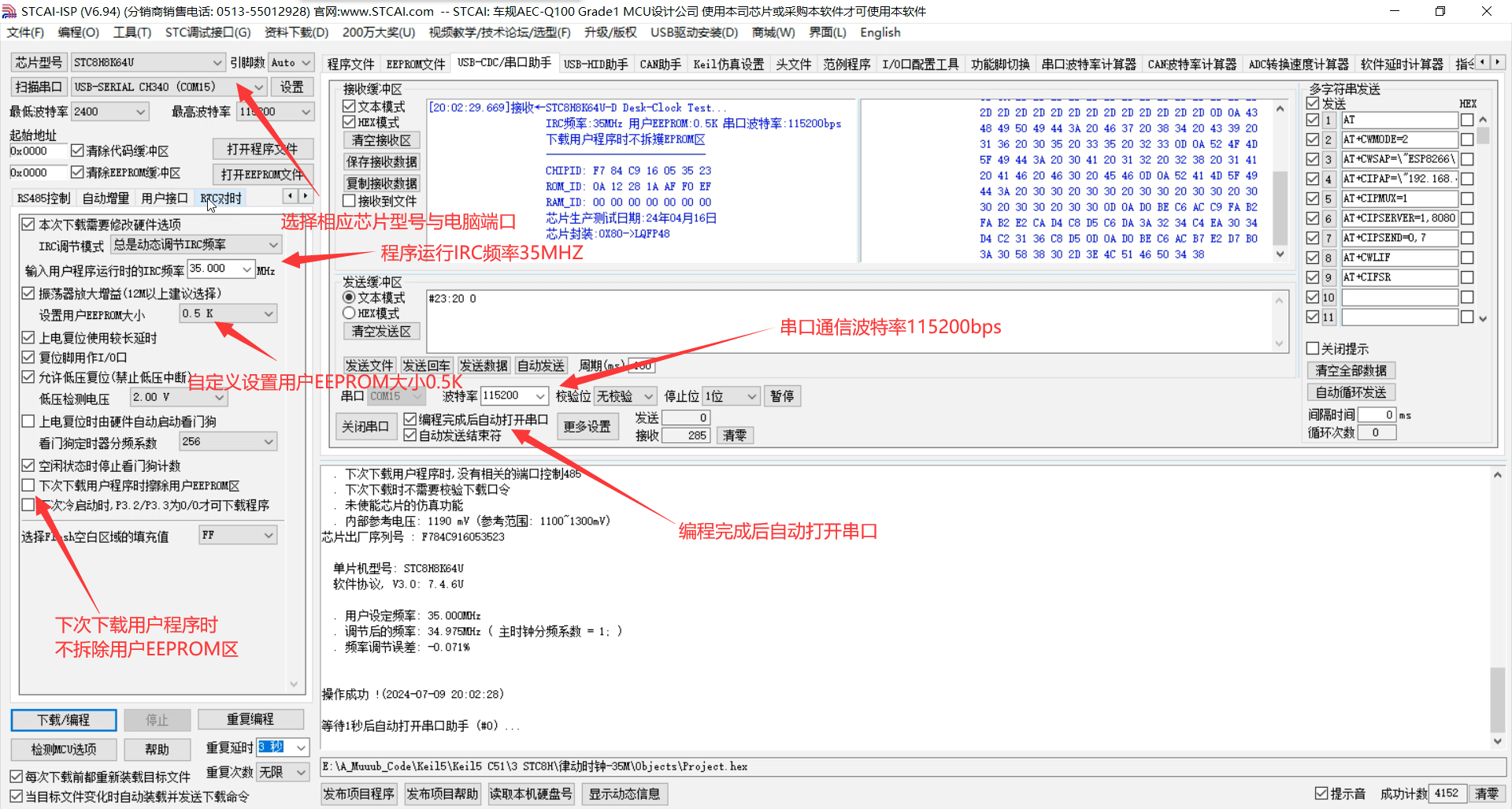
1. Select the corresponding chip model and computer port
. 2. Microcontroller IRC operating frequency: 35MHz
3. Set user EEPROM size: 0.5K
4. Do not erase the user EEPROM area when downloading the user program next time
. 5. Automatically open the serial port after programming is completed
. 6. Serial communication baud rate: 115200bps
7. After successful program download, the chip ID information will be automatically read and transmitted to the host computer.
VI. RTC and Alarm Clock Time
Synchronization In the STC-ISP software, select the RTC time synchronization interface and open the serial port:
1. RTC time synchronization baud rate: "115200bps", command header: "@", automatically obtain system time.
2. Alarm clock time synchronization baud rate: "115200bps", command header: "#", format: "hour:minute start/stop" (1 start 0 stop)
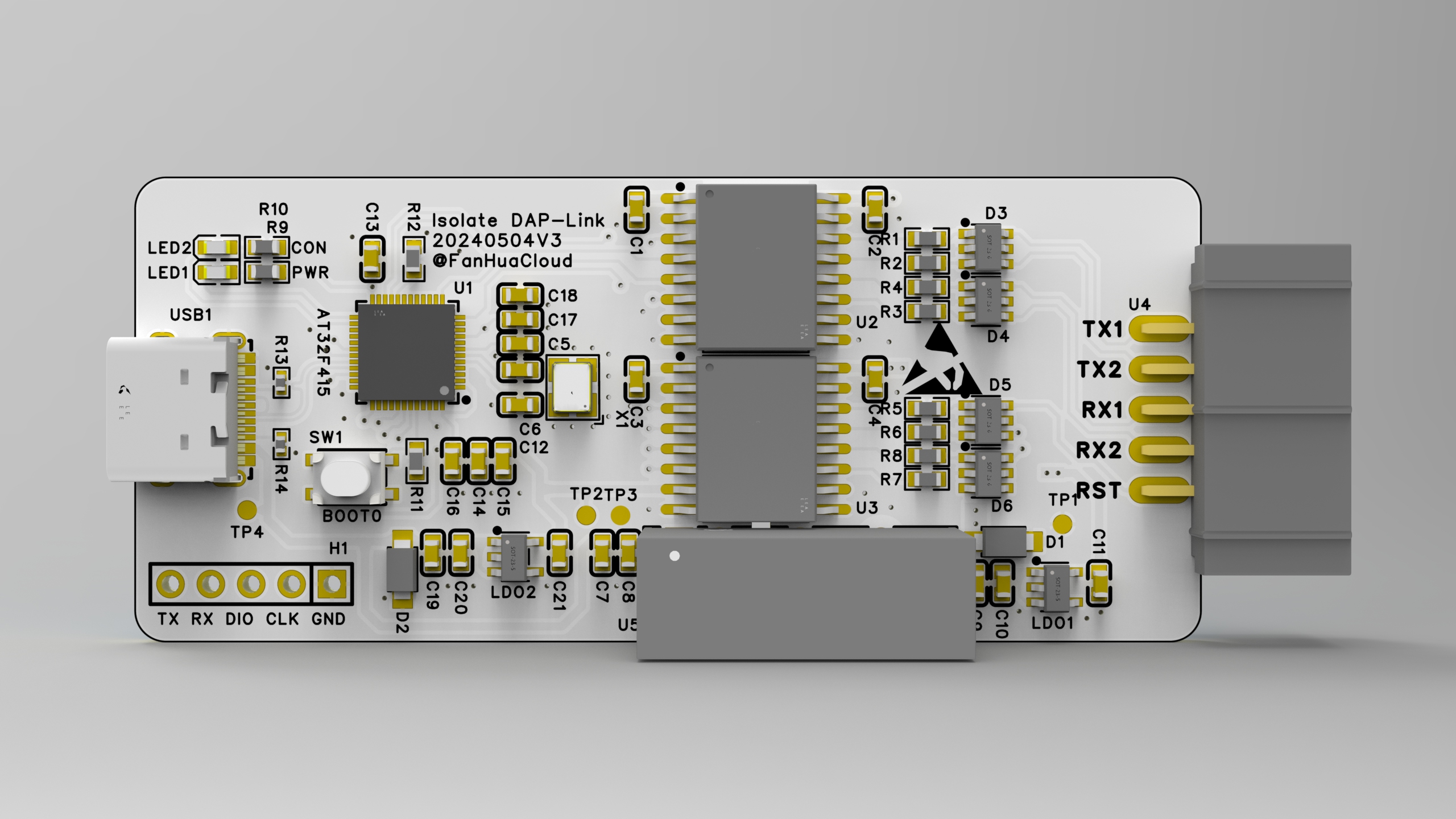
AT32F415-based Isolated DAP-Link Debugger
Update Log:
20240522 First Release;
20240527 Firmware Update 20240527.hex, Optimized Serial Port Transmit/Receive Performance
; 20240611 Firmware Update 20240611.hex, Optimized SWD Speed, Supports Dual Serial Port Functionality; Older Firmware Version Available for Host Computer Use ;
20240717 Updated 3D Printed Shell Link.
Main Functionality:
Based on the AT32F415 chip from Arteli Technology, this isolated DAP-Link debugger supports up to 1500V isolation (up to 5KV without an isolated power supply), and can be used to debug motor control boards and other devices.
Using the CherryUSB framework, combined with optimized DAP-Link code, it can achieve high-speed downloads and 4M serial communication under USB FS.
Design Highlights:
1. USB Type-C design for convenient long-distance debugging.
2. Uses Chuanshi micro isolation chips to achieve full isolation between power and signal, preventing high voltage from entering the computer circuit through signal lines.
3. 5V isolated power supply (optional) to power isolated signals and devices, with short-circuit protection.
4. Uses a 3U gold-plated horn-shaped connector (optional) for a more refined appearance.
5. Keeps material costs low.
Software Functions:
1. DAP SWD download/debugging; oscilloscope measured a maximum SWD frequency of approximately 8MHz.
2. USB to serial port, achieving 4MHz baud rate without character loss (a second serial-to-USB port can be developed).
3. Supports USB program updates; program can be refreshed without disassembling the device.
4. Supports host computer, which can be used to configure DAP IDs for easy differentiation of multiple DAPs
. 5. Serial number generated based on the chip's unique code to prevent duplicates.
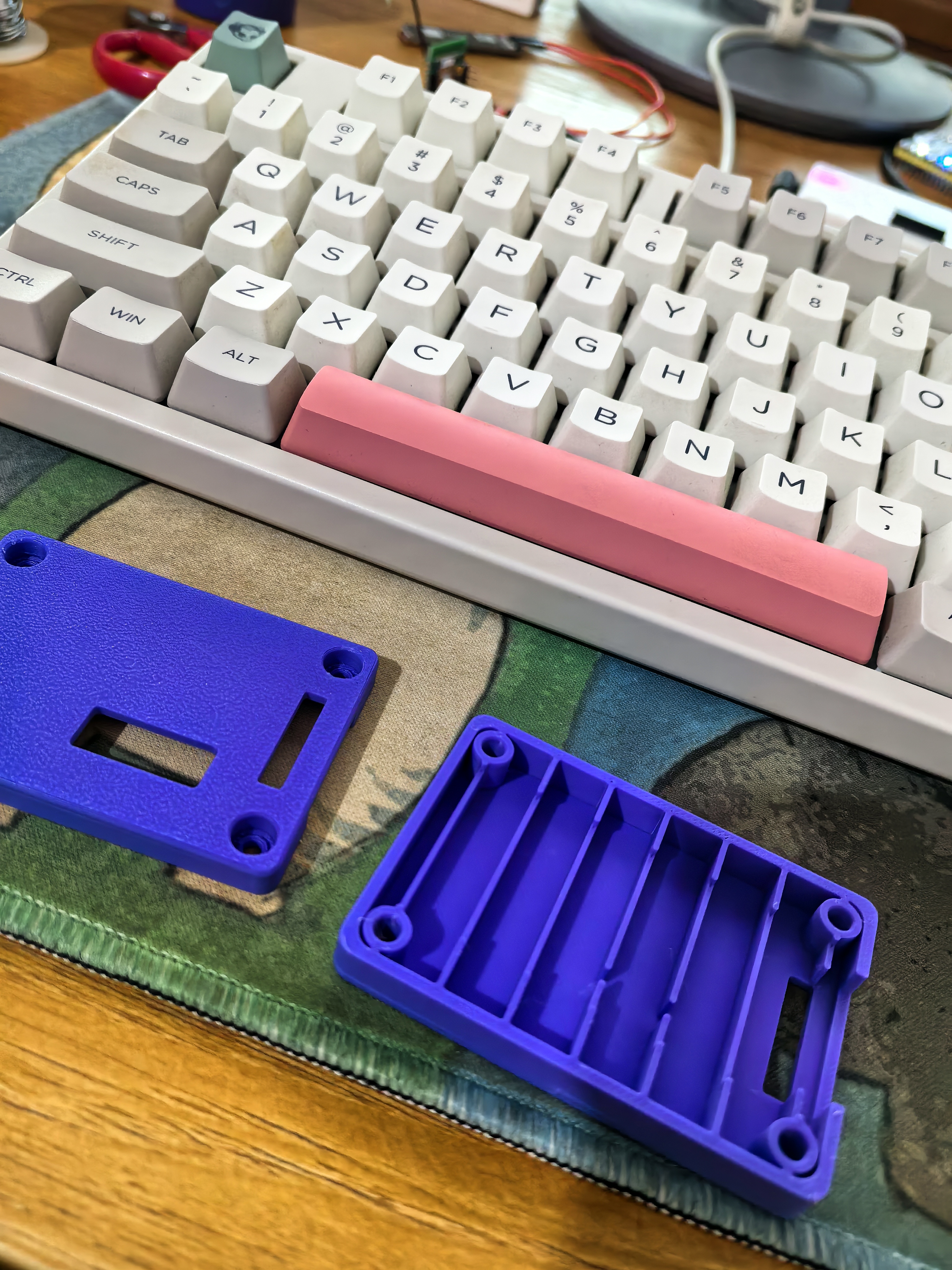
Shell Printing and Assembly
Files: Shell.stl The lower shell .stl
slice file can be found in the attached outer shell .3mf file.
For detailed instructions, please see: https://makerworld.com.cn/zh/models/335477#profileId-266989
. After printing, use a soldering iron to heat-melt four nuts into the holes, then place the board inside. Finally, use M3*5 screws to screw them in from the top. See the image below for reference.
Screw purchase link (select color category: M3*5 (100 pieces)):
https://detail.tmall.com/item.htm?id=624811454452&spm=a1z09.2.0.0.1de82e8d8Zps2p&_u=h2dklb456894
Heat-melt nut purchase link (select color category: M3*6*4.2 [100 pieces]): Original purchase links: 1. 10P Horn-shaped connector (select color category: 10P, specification: straight pin): https://item.taobao.com/item.htm?_u=m2dklb45f734&id=712321967438&spm=a1z09.2.0.0.e8dd2e8dC6CepY
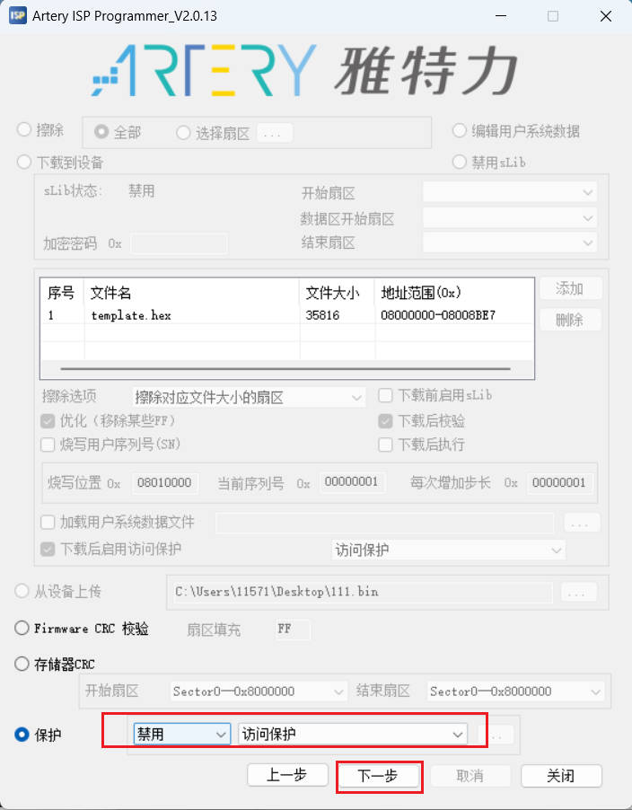
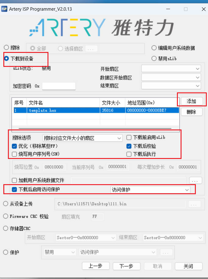
2. White Type-C connector (buy this if you want a nicer look; refer to the BOM for normal purchase): https://item.szlcsc.com/3272613.html 3. 4. Isolation Power Supply (Select B0505S-3WR2 [5V to 5V 600mA], also available at LCSC Mall): https://detail.tmall.com/item.htm?_u=m2dklb45d901&id=612898477250&spm=a1z09.2.0.0.e8dd2e8dC6CepY 5. Isolation Chip (Select CA-IS3742HW, CA-IS3741HW): https://item.taobao.com/item.htm?_u=m2dklb45ea32&id=609653319378&spm=a1z09.2.0.0.e8dd2e8dC6CepY 5. AT32F415CCU7: https://item.taobao.com/item.htm?_u=m2dklb45fe39&id=650419388165&spm=a1z09.2.0.0.e8dd2e8dC6CepY 6. ESD Tube: https://item.taobao.com/item.htm?_u=m2dklb45580f&id=653799154764&spm=a1z09.2.0.0.6b752e8dC0aQg2 (Other components can be purchased according to the BOM). The program is open source ; please select the one_uart branch. For test firmware, please refer to the attachment: 20240523.hex Download the firmware flashing tutorial for https://gitee.com/fhcloud/at_-f415_-dap and download the ISP tool: https://www.arterytek.com/file/download/1720. Press and hold BOOT0 to connect the debugger's USB port to the computer. The computer should hear a USB recognition sound. Select Artery_ISP_Programmer_V2.0.13Artery_DFU_DriverInstall.exe from Artery_ISP_Programmer_V2.0.13Artery_DFU_DriverInstall, double-click to start installing the USB DFU driver. After installation, open ArteryISPProgrammer.exe from Artery ISP Programmer_V2.0.13ArteryISPProgrammer_V2.0.13 to start flashing. This debugger supports a private protocol for connecting to the chip being debugged. Refer to the attached "Isolated DAP HID Communication Protocol" for the protocol. A host computer .7z file can be used for control. [Image displayed]


Isolation DAP HID Communication Protocol.pdf
Host computer .7z
20240523.hex
20240527.hex
20240611.hex
.3mf casing
shell .stl
lowershell.stl
PDF_AT32F415-based isolated DAP-Link debugger.zip
Altium_AT32F415-based isolated DAP-Link debugger.zip
PADS_AT32F415-based Isolated DAP-Link Debugger.zip
BOM_AT32F415-based isolated DAP-Link debugger.xlsx
91223
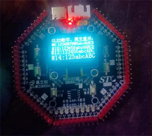
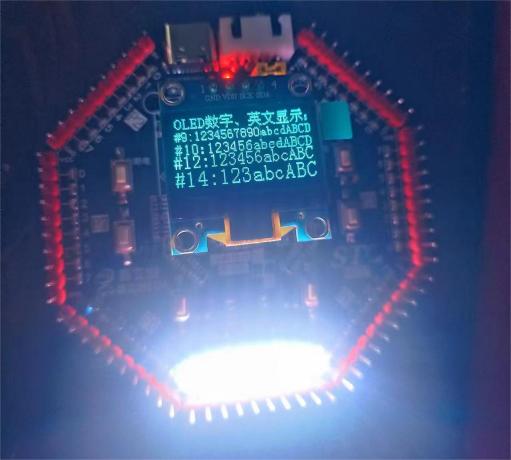
STC32 Eight-Sided Exquisite Development Board
Development board based on STC32G design.
This development board is based on the STC32G design, referencing the official "Dragon Slayer" development board.
Board resources include:
all I/O ports are brought
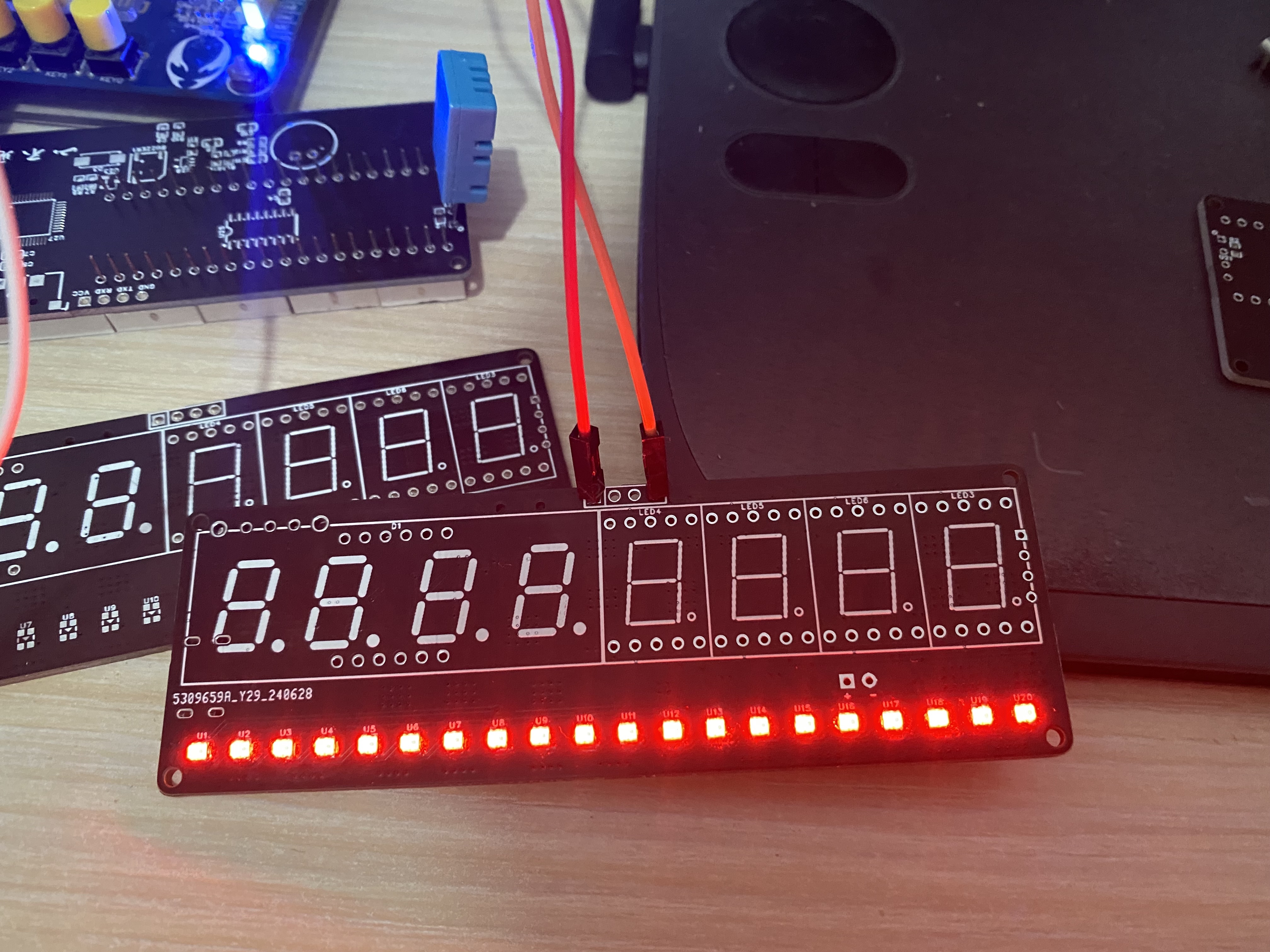
out, 49 onboard LEDs , 8 DS18B20 LEDs, and
a reserved I²C OLED screen interface (an SPI interface was omitted due to my OCD; for compatibility, one wouldn't be centered...). No CAN interface chip is included, but all I/O ports are brought out; if you need CAN functionality, purchase a CAN module. It supports STC USB hardware download and all USB-to-TTL serial downloaders (verified, but USB hardware download only works correctly when switched to 3.3V; the reason is unknown. USB TTL works normally with both 5V and 3.3V). I'm a farmer in my 30s, so I can't dedicate all my time and energy to this; I only have time to work on it during the off-season. Since it's all self-taught, errors are inevitable. I welcome corrections from experienced developers! Front view of the board (the 5V and 3V3 silkscreen markings are reversed; the open-source PCB has corrected this). Back view of the board (the TTL interface silkscreen markings were forgotten; the open-source PCB has them). 48 I/O LED test, OLED test , WS2812B test (requires switching to 5V).


PDF_STC32 Eight-Sided Exquisite Development Board.zip
Altium_STC32 Eight-Sided Development Board.zip
PADS_STC32 Eight-Sided Exquisite Development Board.zip
BOM_STC32 Eight-Sided Exquisite Development Board.xlsx
91224
[Spark Project] H743 Flight Controller (100 Yuan)
An H743 flight controller with a cost of less than 100 yuan.
Project Notes:
7.13 Fixed the incorrect silkscreen direction of the 5V DC-DC diode;
6.20 Optimized power supply routing and adjusted the pin order of the GPS terminals. Previously, TX and RX were reversed. The BF firmware was recompiled, and the previous GPS compass was no longer recognized.
This flight controller is built using an STM32H743VIT6. The minimum resistor and capacitor size is 0.402 for easy soldering. H743 flight controllers on Taobao start at 199 RMB; this flight controller's production cost is under 100 RMB. Supports BF, INAV, and APM firmware (latest firmware available in QQ group: 154782128).
First-time use of the high-performance BMP390 barometer
. Average operating current: 3.2μA (1Hz). Barometric
pressure detection range: 300~1250hPa
. Absolute pressure accuracy: ±0.50hPa (P=300...1100 hPa T=0...65 °C).
Relative pressure accuracy: ±0.03hPa (P=700…1100 hPa T=25…40°C).
Temperature drift coefficient: ±0.6Pa/K (25°…40°C at 900 hPa).
Absolute temperature accuracy: ±1.5℃ (0…65℃).
Supported resolution: 0.016Pa (high-precision mode).
Supported sampling rate: 200Hz.
Operating temperature: -40~85℃.
Open source license.
This hardware design is based on CC-BY-NC-SA. Released under the 4.0 license, this work is for DIY learning and exchange among enthusiasts only, and any form of commercial use is strictly prohibited. This design is provided "as is," without any guarantee of quality or warranty. We are not responsible for any consequences or liabilities arising from product design, improper operation, or violation of local laws and regulations that result in damage to the creator's or any third party's personal safety, property, or resources.
CC-BY-NC-SA 4.0, Creative Commons Attribution-NonCommercial-ShareAlike License.
CC: Creative Commons license.
BY: Attribution; you must give appropriate credit, provide a link to this license, and indicate whether modifications were made (to the original work).
SA: ShareAlike; if you remix, transform, or build upon this work, you must share and release your contributions under the same license as the original.
NC: NonCommercial; you may not use this work for commercial purposes.
Flight controller configuration is as follows:
Hole spacing: 20/30.5mm
; Tuning parameters: Type-C;
Main MCU: STM32H743;
Gyroscope IMU: ICM42688 * 2
; Character overlay OSD: AT7456E
; Barometer: BMP388/BMP390
; Blackbox: 128MB
; Input voltage: 3S-8S
; DC-DC1: 5V/3A;
DC-DC2: 9V/2A;
LDO: 3.3V/500mA; 2-channel
flight controller firmware: BF, INAV, APM;
Wiring instructions.

Mall component sourcing.xlsx
video.mp4
betaflight_4.5.0_ZEROH743.hex
PDF_【Spark Project】H743 Flight Controller for 100 Yuan.zip
Altium_【Spark Project】H743 Flight Controller for 100 Yuan.zip
PADS_【Spark Project】H743 Flight Controller for 100 Yuan.zip
BOM_【Spark Project】H743 Flight Controller for 100 Yuan.xlsx
91225
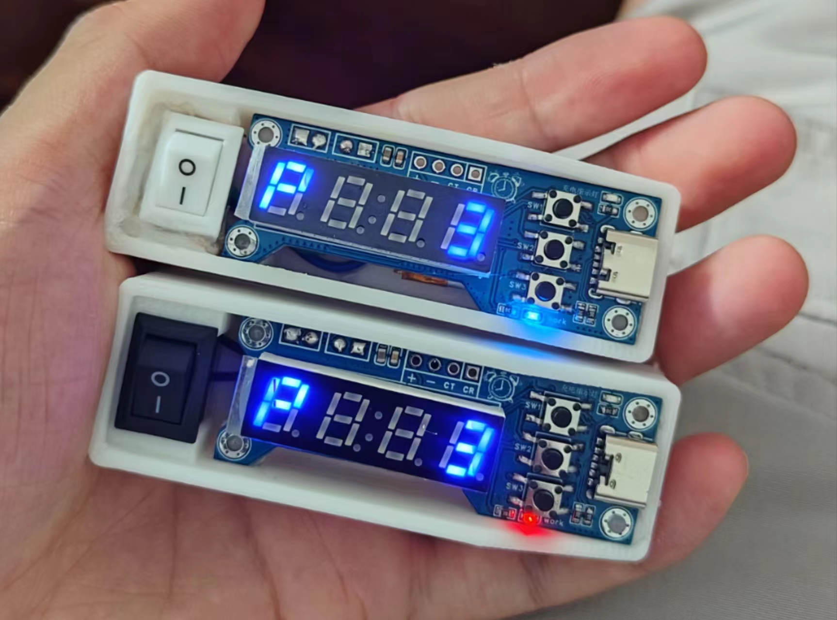
Instant noodle timer
Instant noodle timer based on STC8 series microcontroller
Essentially, it's a timer with a ramen noodle lid, hence the name "ramen noodle timer" (self-deprecating humor).
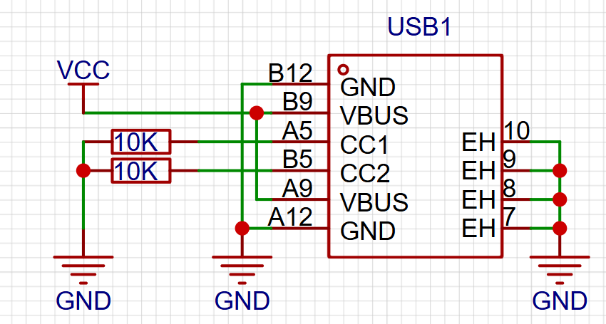
The device provides a countdown
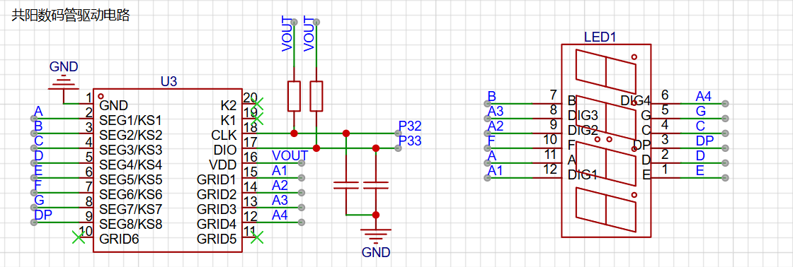
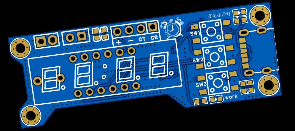
function, sounding an alarm when the time is up. It has a lithium battery and is portable. The device features a 120mAh lithium battery that can be charged via a Type-C port. Note that the CC1 and CC2 pins require external pull-down pins. The device uses a TP4054 chip for charge/discharge protection of the lithium battery. The display module uses a four-digit LED display and a TM1637 driver chip. It has three buttons for "increment/decrease" and "start/stop timing," located vertically on the right side of the LED display. Two status indicator lights are present: an external power input indicator that illuminates when there is external power input to the Type-C port, indicating that the battery is charging; and a VOUT output indicator controlled by an external switch. When the switch is closed, the device starts working; otherwise, it does not start. The VOUT status light illuminates when the device starts. Interface Description: The device PCB has three sets of interfaces, arranged horizontally above the digital tube. The image below shows the front and back of the PCB. The leftmost interface is the battery interface; connecting a lithium battery to this interface provides power to the device. Next to it is the external switch interface; connecting the switch to this interface enables power on/off switching. The rightmost interface is the programming interface, used for chip programming. This device uses the STC8G1K08A chip; please use a compatible serial programmer for programming. The program is developed using STC-ISP + Keil5 + VS Code. A hex file is provided in the attachment. tm1637.c / tm1637.h provide the digital tube display control function. main.c is the main program file. ST8HGH is the header file. #include "STC8G.H" #include "INTRINS.H" #include "tm1637.h" /** * Pin definitions */ sbit Buzz_IO = P5^4; // Buzzer /** * Variable definitions */ unsigned char mode_flag = 0; // Default is parameter setting mode unsigned char data_min = 3; // Timer value unsigned int back_time_s = 0; // Countdown value unsigned char isok = 0; // Countdown end flag /******************System Initialization**************** */ void System_Init(){ P5M0 |= 0x10; P5M1 &= ~0x10; // Buzz_IO set to push-pull output Buzz_IO = 0; P3M0 &= ~0x0c; P3M1 &= ~0x0c; P3M0 &= ~0x03; P3M1 &= ~0x03; P5M0 &= ~0x20; P5M1 &= ~0x20; } /******************System Initialization**************** */ /******************Button Monitoring**************** */ #define Button1 0 #define Button2 1 #define Button3 2 void ButtonClick(unsigned char button){ switch (button) { case Button1: // Increase if (mode_flag == 0) { data_min += 1; if(data_min > 99){ data_min = 99; } } break; case Button2: if (mode_flag == 0) { mode_flag = 1; // Enter countdown mode back_time_s = data_min * 60; }else{ mode_flag = 0; // Parameter mode back_time_s = 0; } break; case Button3: // Decrease if (mode_flag == 0) { data_min -= 1; if(data_min data_min = 1; } } break; default: break; } } void keyCheckLoop(){


P55 = P30 = P31 = 1; // Pull up the button
if(P55 == 0){
ButtonClick(Button3);
while(P55 == 0);
}
if(P30 == 0){
ButtonClick(Button1);
while(P30 == 0);
}
if(P31 == 0){
ButtonClick(Button2);
while(P31 == 0);
}
}
/******************Button Monitoring**************** */
/******************Countdown Module**************** */
void Delay300ms(void) //@11.0592MHz
{
unsigned char data i, j, k;
_nop_();
_nop_();
i = 13;
j = 156;
k = 83;
do
{
do
{
while (--k);
} while (--j);
} while (--i);
}
void stopCheck(){
unsigned char number = 0;
if (isok == 1) // Timing ends
{
for (number = 0; number
{
Buzz_IO = 1;
Delay300ms();
Delay300ms();
Buzz_IO = 0;
Delay300ms();
Delay300ms();
Buzz_IO = 1;
Delay300ms();
Delay300ms();
Buzz_IO = 0;
Delay300ms();
Delay300ms(); Buzz_IO =
1 ; Delay300ms(); Buzz_IO = 0 ; Delay300ms ( ) ; Delay300ms( ) ; Timer0_Isr(void) interrupt 1 { timer1_number++; if (timer1_number >= 20) // Triggered once per second { timer1_number = 0; if (mode_flag == 1) { back_time_s -= 1; if(back_time_s == 0){ isok = 1; } } } } void Timer0_Init(void) //50 milliseconds@12.000MHz { AUXR &= 0x7F; //Timer clock 12T mode TMOD &= 0xF0; //Set timer mode TL0 = 0xB0; //Set timer initial value TH0 = 0x3C; //Set timer initial value TF0 = 0; //Clear TF0 flag TR0 = 1; //Timer 0 starts timing ET0 = 1; //Enable timer 0 interrupt EA = 1; //Enable global interrupt
}
/******************Countdown Module**************** */
/******************Digital Tube Display**************** */
void SHUMA_DISPLAY(){ // Call this method to update the display interface
switch (mode_flag)
{
case 0: //Parameter setting interface
if (data_min
{
TM1637_Display(19,21,21,data_min);
}else{
TM1637_Display(19,21,data_min/10,data_min%10);
}
break;
case 1: //Countdown running interface
TM1637_DisplayInt(back_time_s);
break;
default:
break;
}
}
/******************Digital Tube Display**************** */
void main(){
System_Init();
Timer0_Init();
while(1){
SHUMA_DISPLAY(); //Interface display
keyCheckLoop(); //Key detection
stopCheck(); //End monitoring
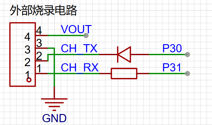
} To program the serial programmer , you need some basic STC knowledge; programming itself shouldn't be a problem.
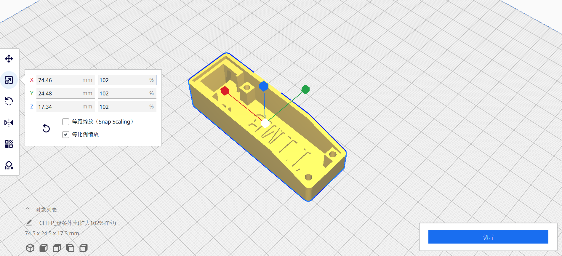
CH_TX / CH_RX represent the TX / RX pins of the serial programmer. Regarding the 3D casing: please expand the casing to 101% or 102% when printing.
Project - Instant Noodle Timer Based on STC8.zip
PDF_Instant Noodle Timer.zip
Altium_instant noodle timer.zip
PADS_Instant Noodle Timer.zip
PDF_Instant Noodle Timer.zip
BOM_Instant Noodle Timer.xlsx
91226
STC8H8K64U-LQFP32 Minimum System Board - One-Click I/O Voltage Switching
This project uses the STC8H8K64U-45I-LQFP32 as the main control chip. It is a core board with complete IO interfaces. It has a dual row of 20-pin headers with a standard 17.78mm pitch, which can be inserted into a perforated board for debugging.
0x01 Project Background:
I saw an article on JLCPCB's WeChat official account announcing the STC & JLCPCB EDA Microcontroller Creative Design Competition, so I immediately signed up to participate.
LED lighting test example.hex
PDF_STC8H8K64U-LQFP32 Minimum System Board - One-Click I/O Voltage Switching.zip
Altium_STC8H8K64U-LQFP32 Minimum System Board - One-Click I/O Voltage Switching.zip
PADS_STC8H8K64U-LQFP32 Minimum System Board - One-Click I/O Voltage Switching.zip
BOM_STC8H8K64U-LQFP32 Minimum System Board - One-Click IO Voltage Switching.xlsx
91227
Power meter without USB interface
After researching online, I found that most power meters use a USB interface, meaning they can only be measured if the device under test is powered by USB. If the device doesn't have a USB port, measurement is impossible. This particular device uses a 3-pin connector to connect to the device under test and measure voltage and current.
I. About Me:
A soon-to-be graduate from a vocational college, I was forced to complete a year-long internship. I won second prize in the Guangdong Provincial Electronics Competition. Seeing the Spark Program, I was eager to participate and decided to create an open-source project.
II. Power Meter Description:
1. Brief Explanation:
I found many open-source power meter projects online, but they all require USB connection, which is limited in some scenarios. Therefore, my power meter's main feature is that it connects to the device under test via terminal blocks.
2. Solution Description:
Current acquisition uses the INA213 low-end measurement solution. Voltage is achieved through a voltage divider using two resistors, followed by differential and common-mode filtering. The ADC values output from the current and voltage acquisition circuits are directly connected to the 16-bit SDADC peripheral on the main control chip. The main control chip is an STM32F373CCT6. A serial port and an SWD download interface are provided. The display uses IIC_OLED 0.96. A 24C02 and OLED are provided, using one IIC, but the V2_01 version (the latest version) code is not used because I am currently too busy to work on the GUI; I will add it later when I have time.
3. Wiring Instructions:
The wiring interface is a 3-pin terminal block. It has silkscreen markings A, B, and C. A connects to the VCC of the power supply, B connects to the GND of the measuring device, and C connects to the GND of the power supply. A and B form a parallel connection to measure voltage, while B and C form a series connection to measure current using the low-end method.

4. PCB Instructions:
The power indicator light does not illuminate upon power-up, possibly due to STM surface mount technology or other reasons. The 24C02 version code is unusable and can be left unsoldered. The same applies to the three buttons.
5. Housing Instructions:
This housing has not been verified. A simple housing design was provided, but because this issue was not considered during PCB design, the housing used in this case needs to be glued on. An M2 screw can be added to the buttons and 24C02; the housing has sufficient space, and a simple wiring modification is sufficient.
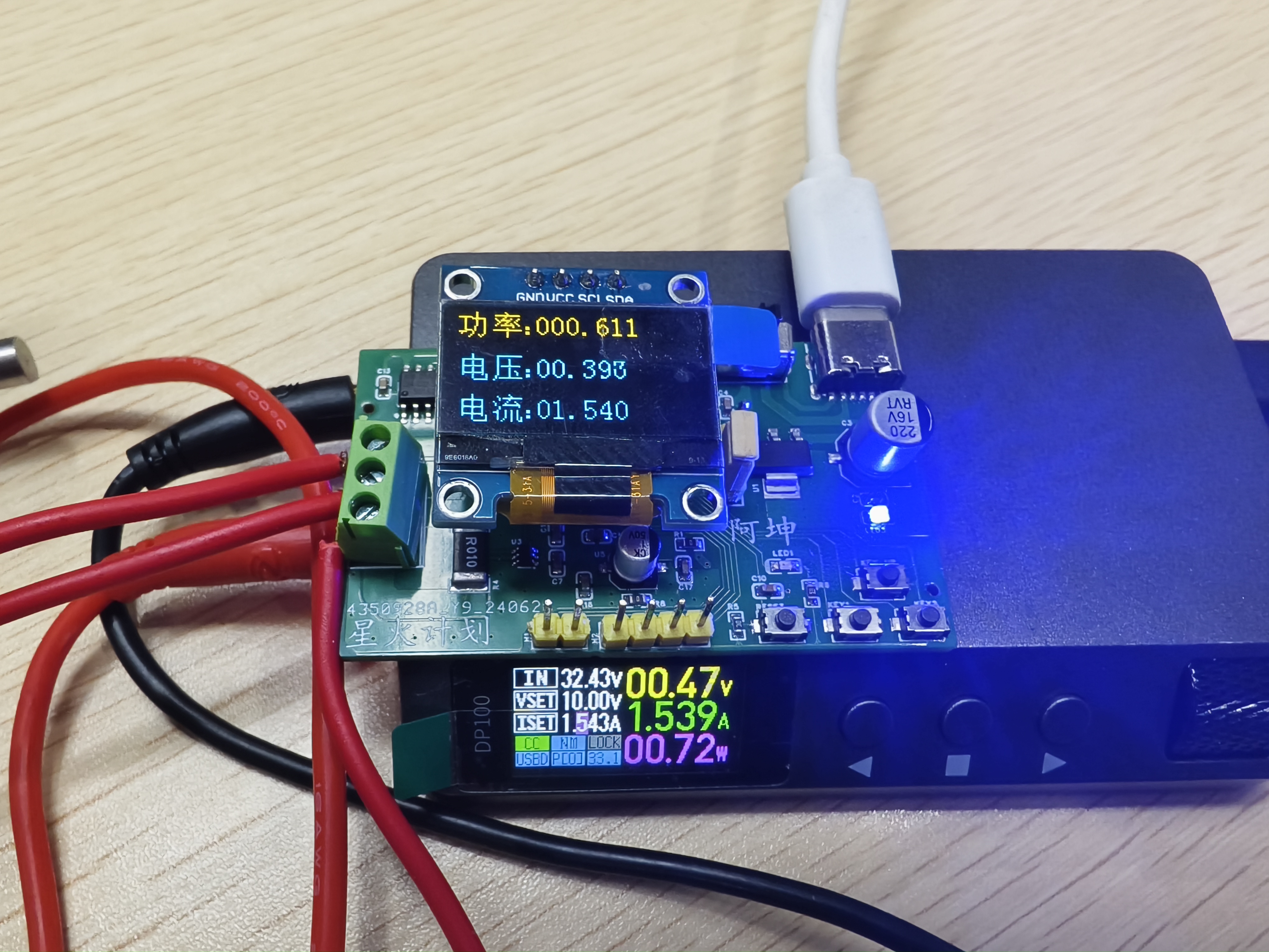
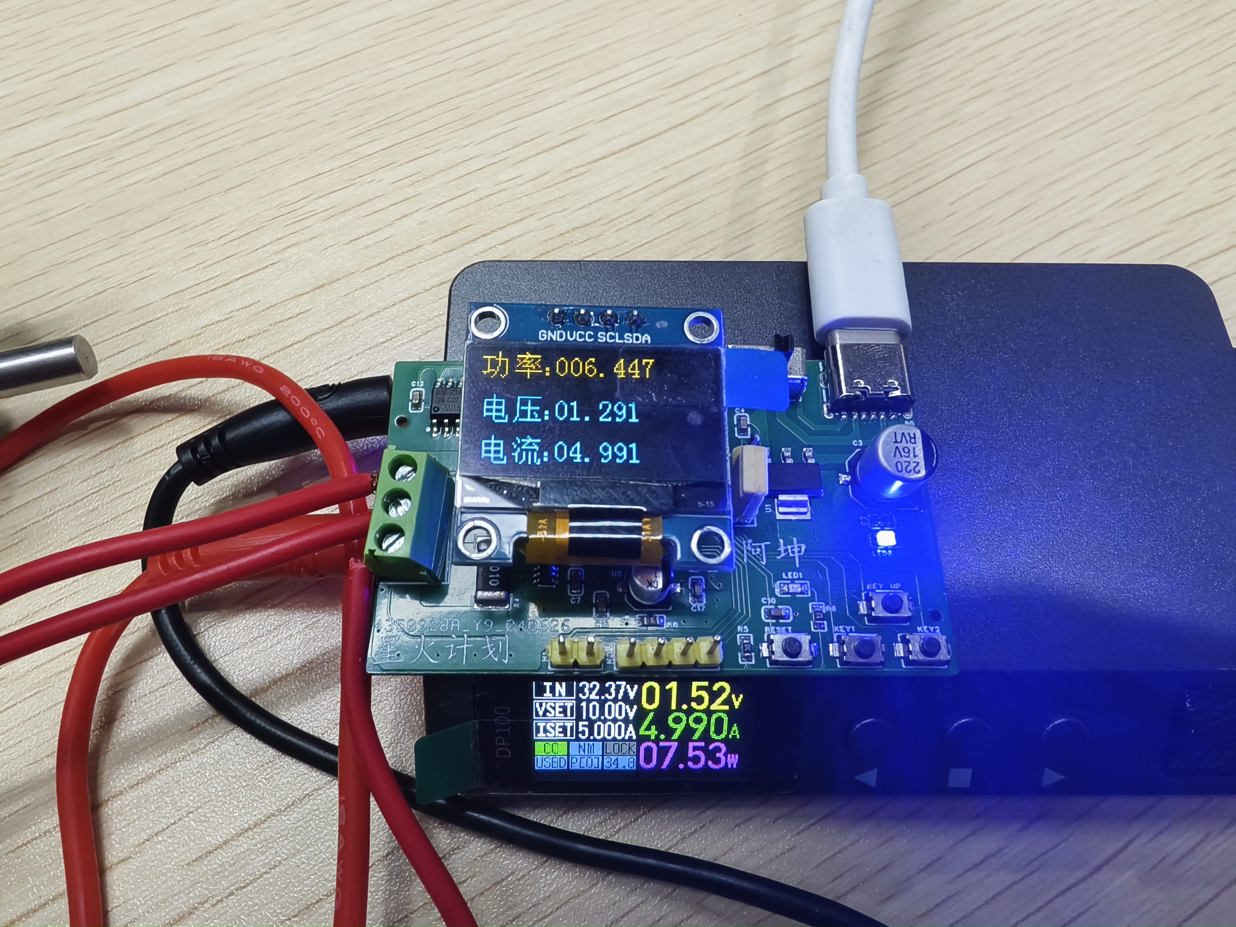
III. Measurement Instructions:
1. Measuring Equipment
: Power Supply: DP100 CNC power supply (Zhengdian Atom) ; Voltage
Measurement: UT136B+
; Current Measurement: Directly observe the DP100 output.
Voltage and current measurements were performed separately because a good load was unavailable.
2. Measurement Accuracy:
I am very satisfied with the current measurement in this project. However, I am not so satisfied with the voltage measurement.
The voltage measurement range is 200mV ~ 30V, with a maximum of 33V.
Below is a graph of the actual measurements.
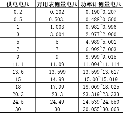
The current measurement range is 20mA ~ 5A. The maximum error between 20mA and 100mA is ±1mA; the maximum error between 100mA and 5A is ±3mA. Yesterday, I accidentally burned out the board and replaced it, but the accuracy is not as high. This is likely related to interference suppression and the fact that it only uses median averaging and linear regression correction.
3. Measurement Accuracy Explanation:
Both voltage and current acquisition used averaging filtering followed by linear regression correction. The voltage acquisition did not use an operational amplifier, so the accuracy is not ideal. I tried it out by soldering in another board for testing, and found that the gain error seemed to vary between different boards. I don't know if this is related to the chip or a poor circuit design.
4. Actual Current Measurement Images
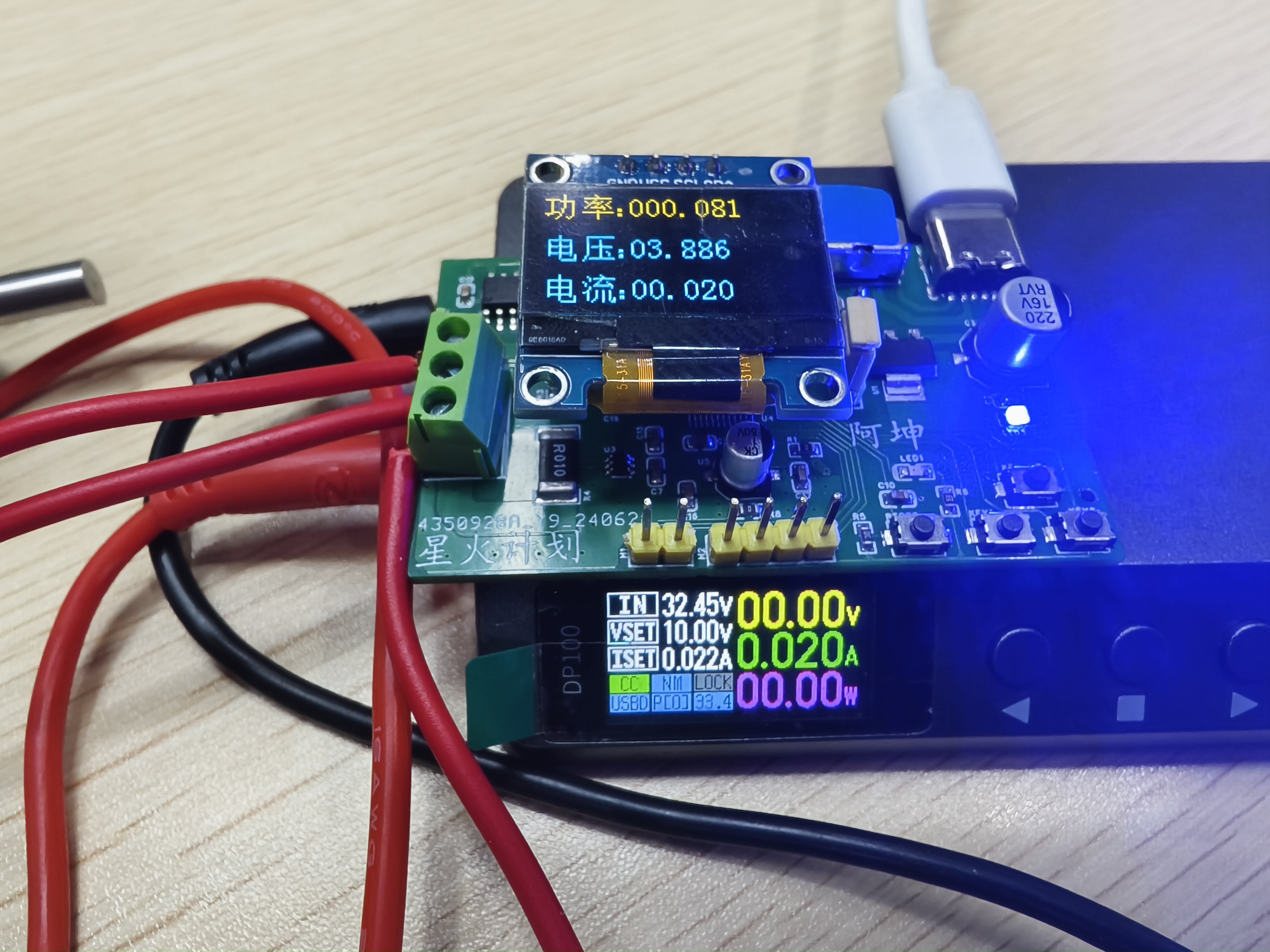
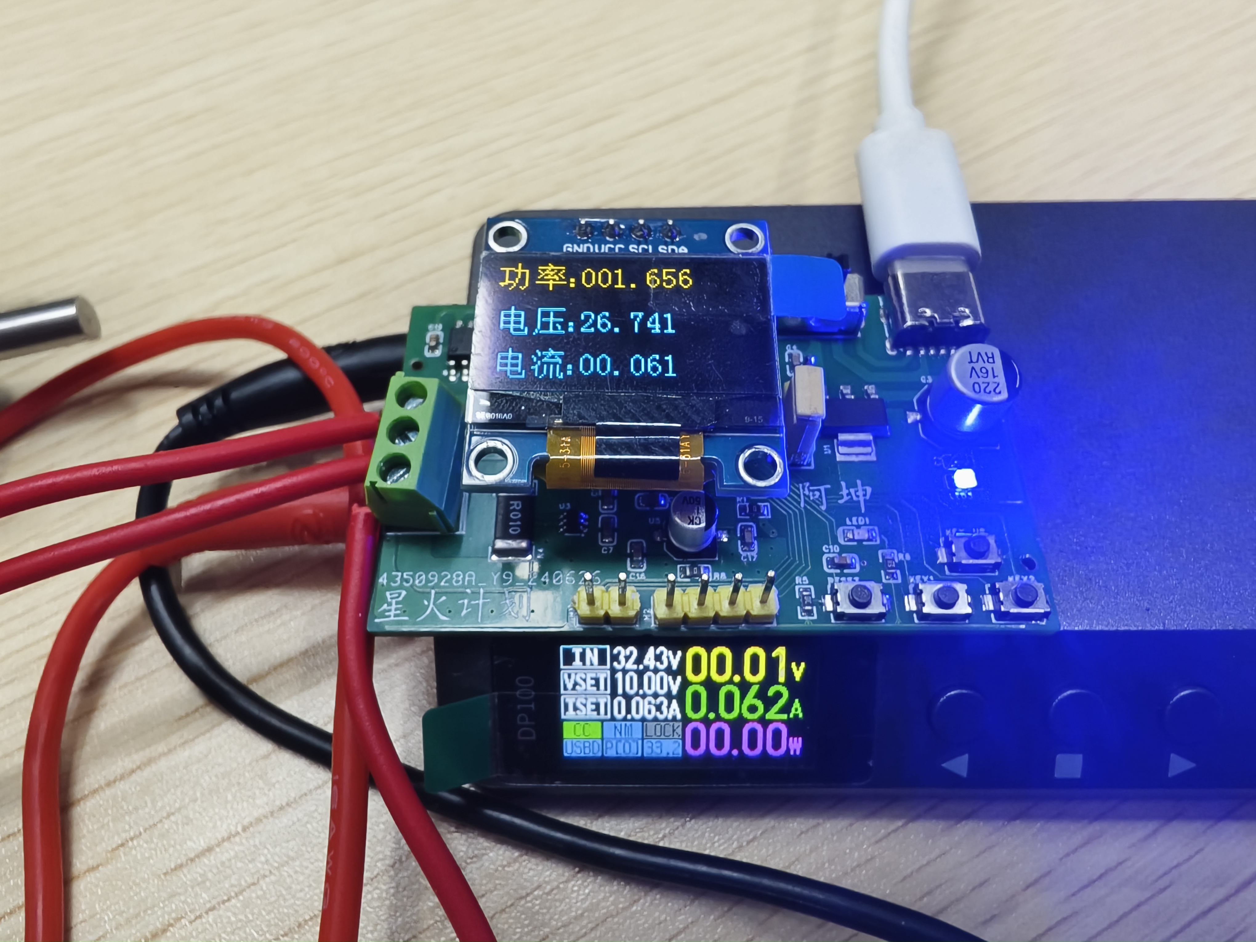

IV. Precautions
It is recommended to use an alloy resistor for sampling. The INA213's full-scale range is 60mV. The size of the sampling resistor to choose depends on the maximum sampling current. I used a 0.01R resistor, which can measure a maximum current of 6A. The recommended accuracy for the voltage divider resistor is 1%. Calculate the voltage divider value yourself. I used 18K and 2k ohms.
V. Demonstration Video
There is no demonstration video yet, but it may be uploaded to Bilibili later.
VI. Code Explanation
The code was developed using CudeMX, Keil 5, and VS Code. CudeMX is used to generate the initialization code, Keil 5 is used for compilation, and VS Code is used for writing the code. This version does not include LED lights, 24C02, or button-related functions.
Attachment 1: Code
Powre_meter_V2_01.zip
PDF_Power Meter (Non-USB Interface)
Altium Power Meter (Non-USB Interface).zip
PADS_Power Meter (Non-USB Interface) .zip
PDF_Power Meter (Non-USB Interface)
Altium Power Meter (Non-USB Interface).zip
PADS_Power Meter (Non-USB Interface) .zip
BOM_Power Meter (Non-USB Interface).xlsx
91228
Summer handheld fan
Handheld fan for summer; adjustable speed 0-255, full charge speed 22 m/s; PWM (10KHz) 0-255 duty cycle control; 0.96-inch OLED display;
Project Description:
Summer Handheld Fan; Adjustable speed settings 0-255, 22 m/s fan speed on full charge;
PWM (10KHz) 0-255 duty cycle control;
0.96-inch OLED display; Supports real-time voltage display;
Supports 9V, 7V, and 5V input charging; Supports power bank functionality, supports BC1.2, Apple, Samsung, QC2.0/3.0, MTK PE1.1/PE2.0, Huawei, and Spreadtrum fast charging protocols;
Uses a 9CM Delta PFC0912DE fan;
Uses the free AIR 001;
Programmed using Arduino IDE.
Special Note: This description does not represent the final version and more details are still needed.
Open Source License
: This project uses the CC-BY-NC-SA 3.0 open source license, i.e., Creative Commons Attribution-NonCommercial-ShareAlike.
CC: Creative Commons Attribution
-Attribution, you must give appropriate attribution, provide a link to this license, and indicate whether modifications were made (to the original work).
SA: ShareAlike. If you remix, transform, or create based on this work, you must share and release your contributions under the same license as the original.
NC: Non-Commercial. You may not use this work for commercial purposes.
For questions and discussions, please join group number: 431030188.
Project-related functions
: 1. Fast charging function:
TYPE-C charging port, located on the back of the project;
supports 5V, 7V, and 9V PD fixed voltage inducement. The specific inducement voltage depends on whether the charger used supports the PD voltage of that level;
for more information, please refer to the IP2326 chip datasheet.
2. Button operation:
The side toggle switch is the main switch, powering the entire system.
The front has a two-position toggle switch; tossing it to the right increases the position by one, and tossing it to the left decreases it by one; pressing it turns on the power bank output function, and pressing it again turns it off.
3. Fan speed control function
: The speed is adjustable from 0-255; PWM drives the MOSFET to adjust the fan's VCC speed;
theoretically supports any 12V fan, as long as GND and VCC are connected correctly.
4. Power Bank Functionality
: Supports power bank functionality, compatible with BC1.2, Apple, Samsung, QC2.0/3.0, MTK PE1.1/PE2.0, Huawei, and Spreadtrum fast charging protocols;
for more information, please refer to the IP6505 chip datasheet.
5. 0.96-inch OLED Screen:
After toggling the side power button, the OLED screen displays the battery voltage and fan speed setting;
Component Description :
1. Delta PFC0912DE server fan;
2. AIR 001 chip;
3. SSD1306 OLED I2C protocol screen; Pin order: GND, VCC, SCL, SDA;
Project Attributes:
This project is a summer handheld fan, first public release, an original project by the author, and has not won any awards in other competitions.
Design Principles:
AIR 001 microcontroller as the main controller;
IP2326 chip to induce fast charging for three 18650 batteries;
PWM drive MOSFETs to adjust fan speed;
IP6505 to implement power bank functionality;
5. 0.96-inch OLED display with I2C communication;
Software Description:
This project is developed using the Arduino IDE.
Software Version History:
2024/06/20 V1.0
2024/7/11 V1.1
Fixed some bugs.
Project Update Log:
2024/7/11
Fixed the original 10K resistor R7 to 49K, schematic updated.
Fixed the unstable power bank function, PCB updated.
Added USB switch OLED display, program updated.
Removed the "+" sign for speed values, added "- - -" to display when speed is zero, program updated.
2024/7/13
Fixed some software bugs, program updated.
For the latest program information, please join QQ group: 431030188.
Image display:
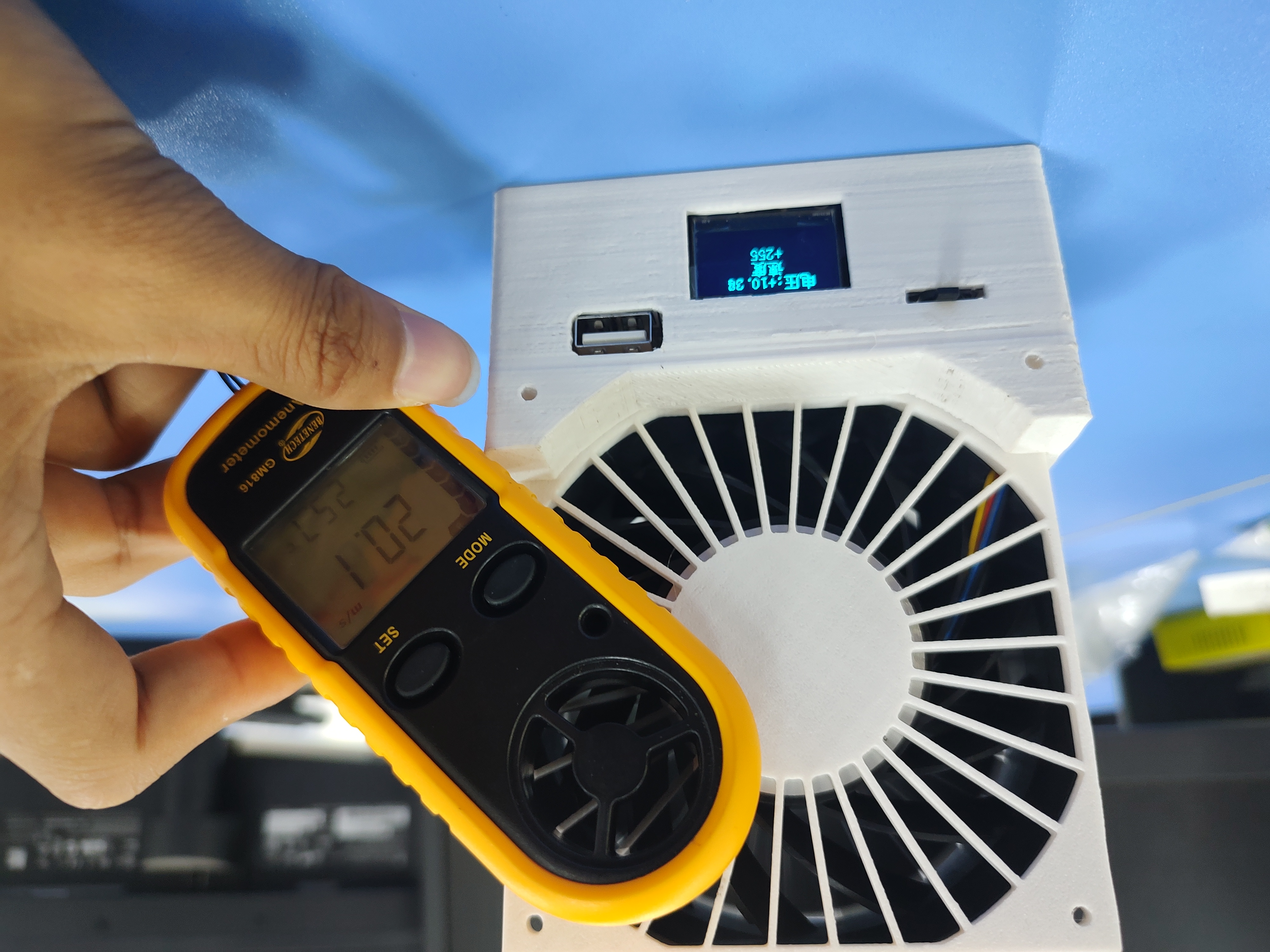
Voltage 10.28V, 255 full speed setting, wind speed 20 m/s.
Detailed display.

Model display:
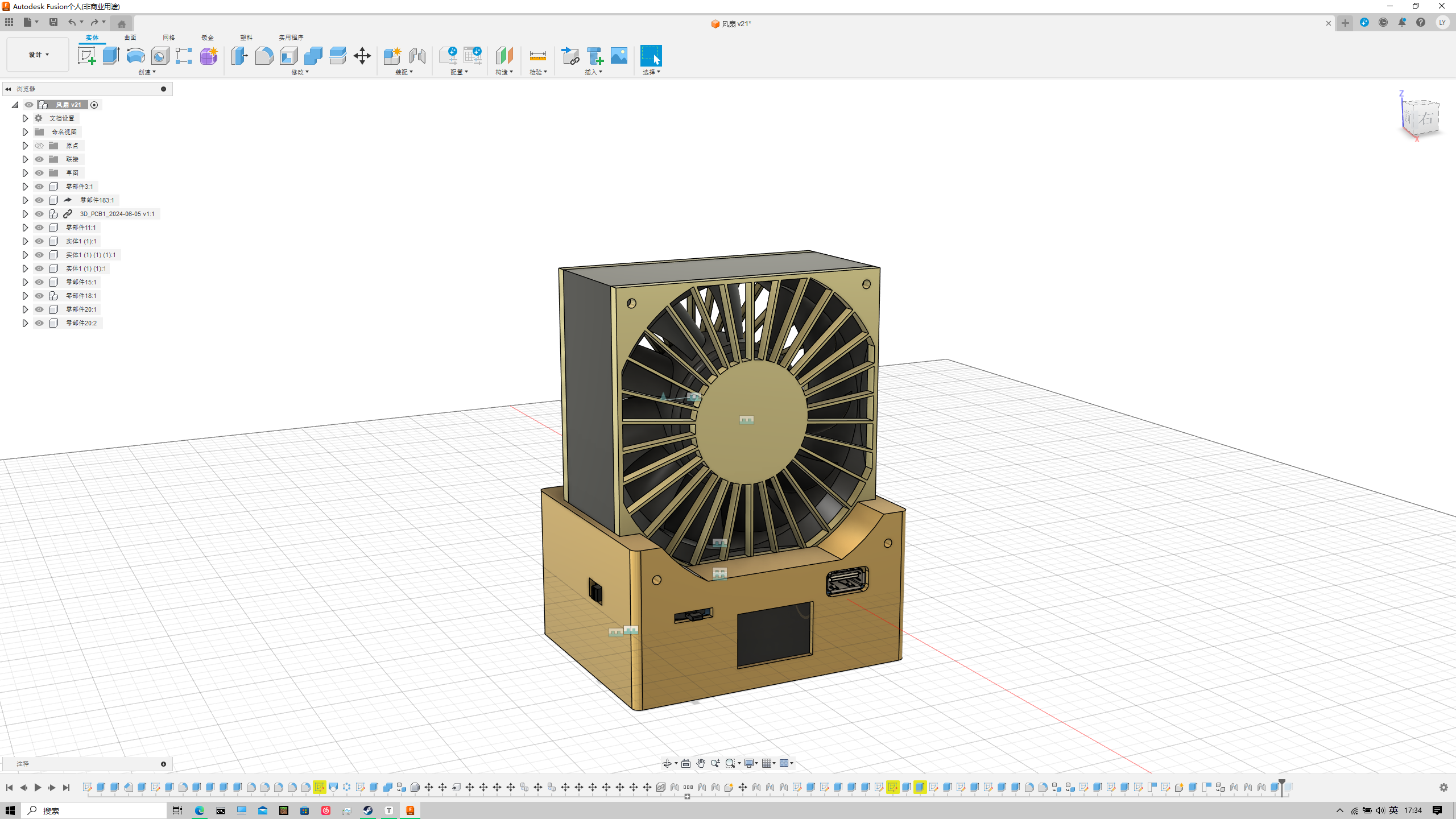
Fusion model.
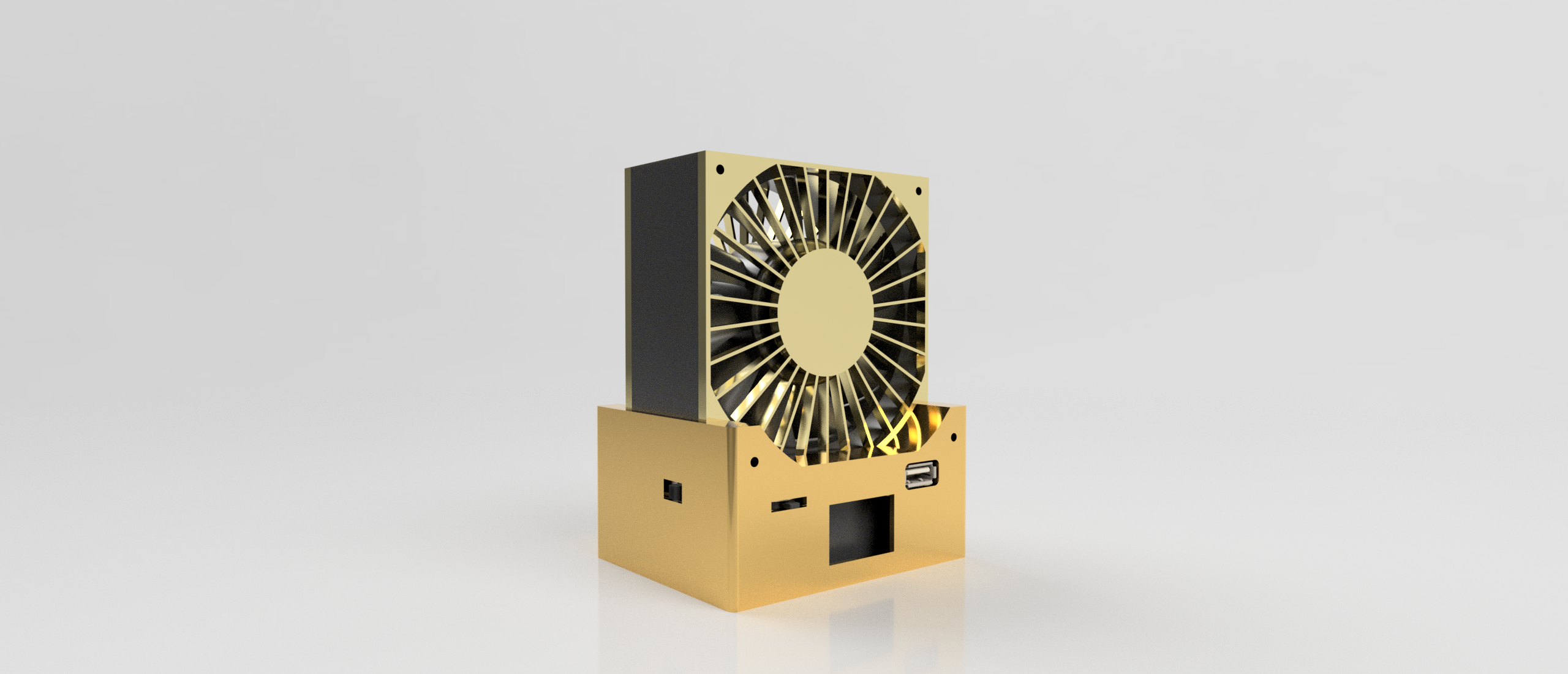
Fusion rendered model.
Safety precautions:
This project uses three 18650 batteries, voltage 12.6V. Please be careful not to short-circuit to avoid danger;
the fan speed is too high, avoid anything being sucked into the fan, especially clothing, and do not touch the rotating fan blades;
any accidents that occur are not the responsibility of the individual.
Summer Fan.zip
PDF_Summer Handheld Fan.zip
Altium_Summer Handheld Fan.zip
PADS_Summer Handheld Fan.zip
BOM_Summer Handheld Fan.xlsx
91230
electronic
 The schematic diagram drawn by a novice is not worthy of explaining the hardware principle. It is just some typical charging, acquisition and minimum system circuits. Many design problems were found in the process of making the physical object (which will need to be modified in future versions):
  [4] The current-limiting resistor for the indicator light in the charging management circuit is too small, causing the charging LED to be too bright and affecting the appearance of the actual product (it is recommended to replace R1 with a resistor of about 3.6K).
  [5] Since there is a clock function in the design, an external 32.768KHz crystal oscillator should be connected to reduce the time error.
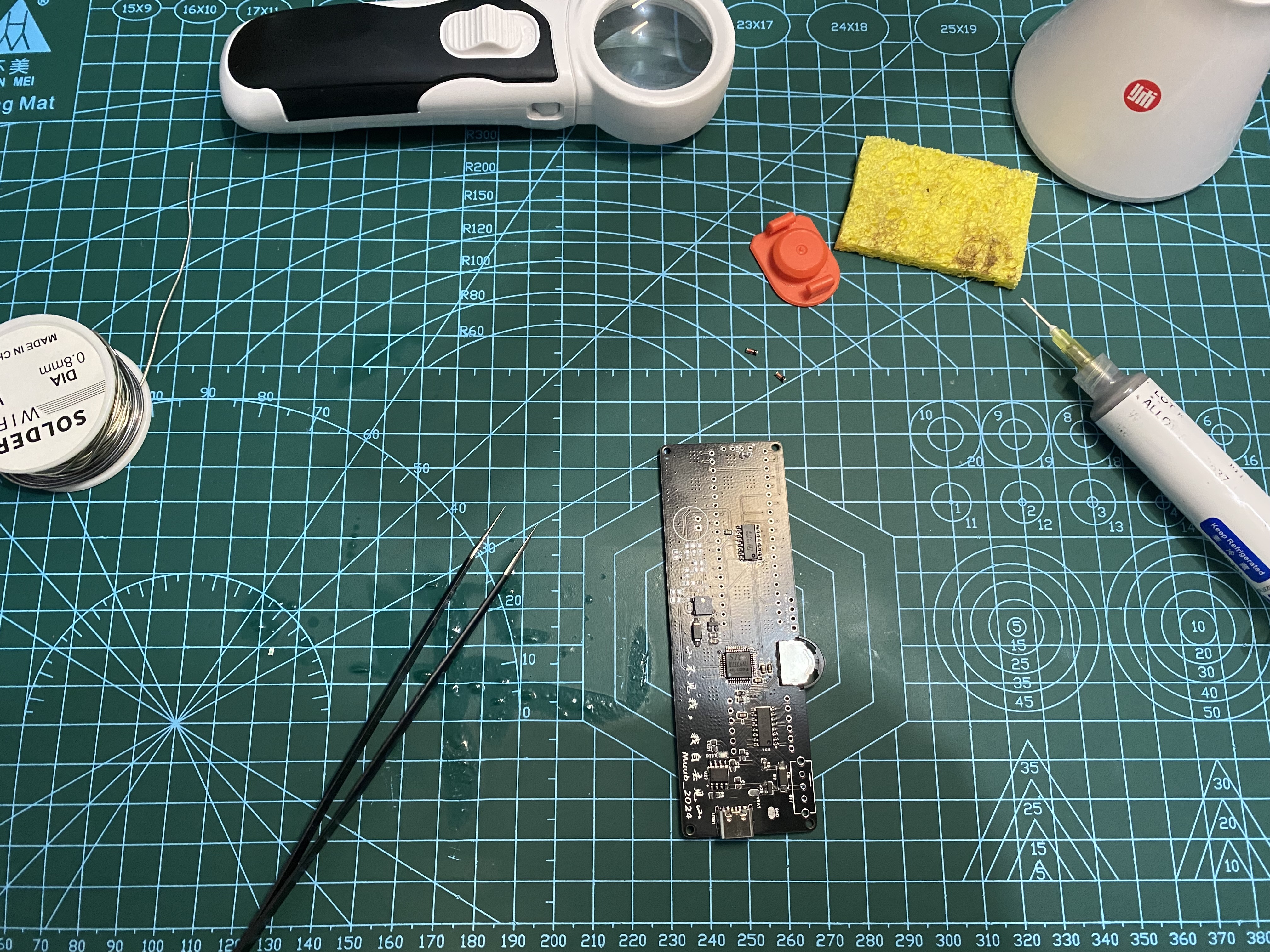


 VI. RTC and Alarm Clock Time
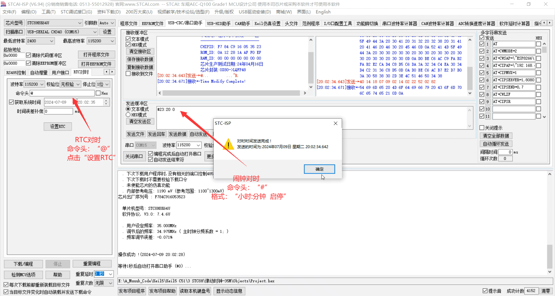


 京公网安备 11010802033920号

 171-001-21NSBLMH


