This project is based on the "Step-by-Step Replica of the EasyMatrix Pixel Clock" tutorial by Bilibili UP master @大聪明的二手脑袋, and incorporates suggestions from netizens. All hardware has been redesigned, and new commonly used hardware functions have been added. The PCB size has been reduced to 26x98mm. The new hardware functions are as follows: 1. Buzzer function (GPIO pins need to be pulled low to eliminate noise; the program is not yet adjusted). 2. Reserved power supply for AMS1117-3.3 (it's rumored that the core board has an onboard 3.3V). LDOs are prone to burning out, so one is reserved. 3. Onboard MAX9814ETD audio amplifier circuit (software configurable mode) 4. Add two Type-C interfaces to adapt to different cable directions (can achieve up, down, left, and right cable output directions for 90-degree plugs, supports power control) 5. Reserved high-precision DS3231 clock chip (used to optimize core heat generation during continuous WiFi operation or to achieve a completely offline clock, not yet adjusted in software) 6. Reserved AHT20 temperature and humidity sensor (affected by heat generation, the casing is insulated, not yet adjusted in software) 7. 5 buttons, one of which supports power control and customization (4 buttons + 1 multi-function button (only on, not yet adjusted in software)) 8. Onboard surface-mount photodiode (used to sense ambient light intensity and adjust brightness) 9. Core board debugging interface has been reserved (used for programming and debugging, does not support power control)
Warm reminder: This project is advanced content. Resistor and capacitor components use 0402 package to reduce size.
For related demonstration videos, please watch the following video:
[Mini version: EasyMatrix] [Pixel Clock] https://www.bilibili.com/video/BV1sh3vefEAk?vd_source=237d7927fbc737e58d9b56ede8115923
For related step-by-step tutorial videos, please watch the following video collection:
[Pixel Clock and Music Spectrum Light Developed with Arduino, No Server Required, ESP32C3 Main Controller, Cost-Control Maniac! Open Source? Absolutely!] https://www.bilibili.com/video/BV1nJ4m1477b?vd_source=237d7927fbc737e58d9b56ede8115923
Declaration: This project is mainly for learning, allowing more people to participate in the production and debugging process and experience the fun of DIY. Commercial use is prohibited! Commercial use is prohibited! Commercial use is prohibited!!!
Finished Product Appearance Display; Finished

Product Composition Display (Light Board and Control Board Already Assembled)
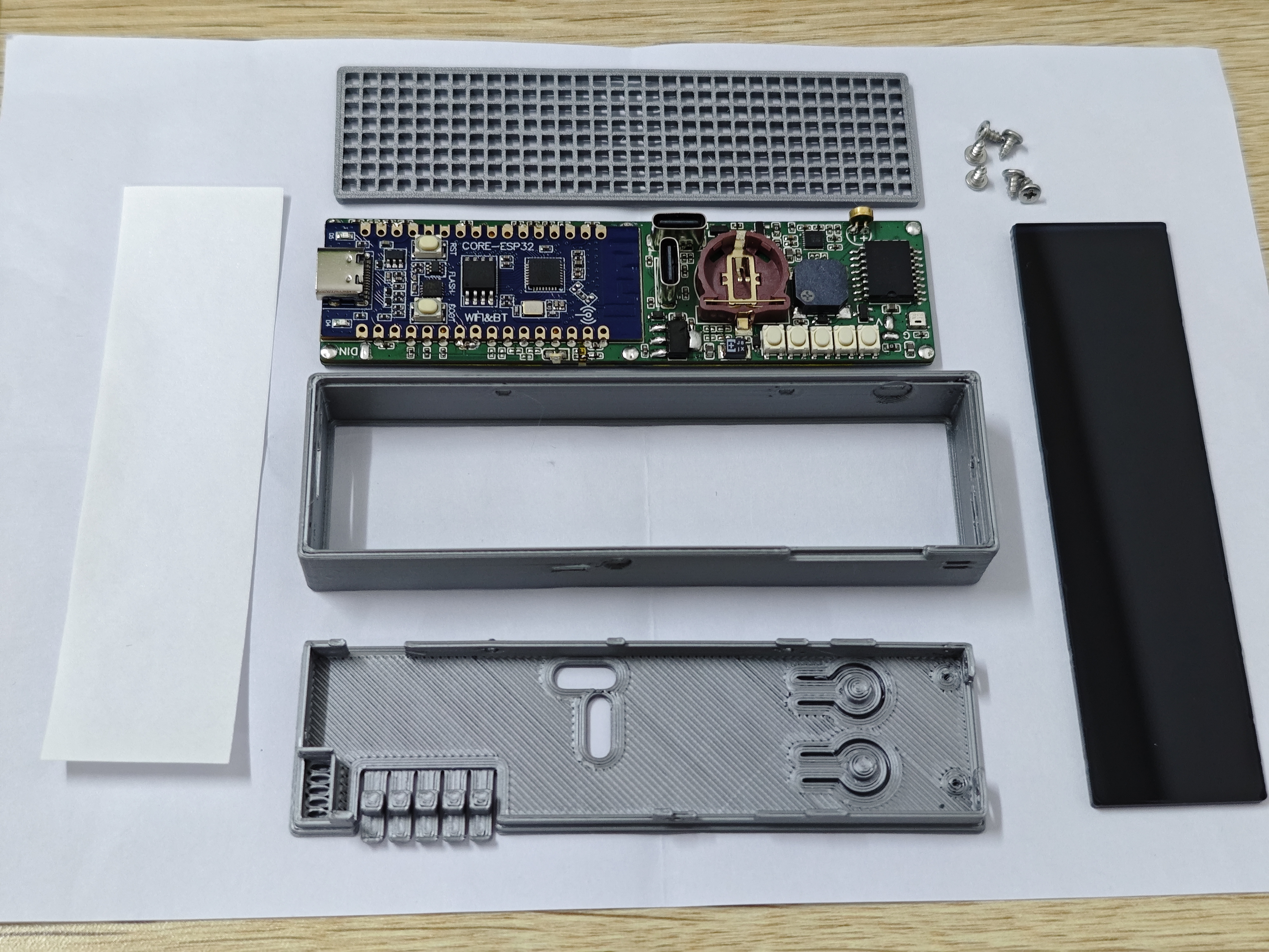
; 3D
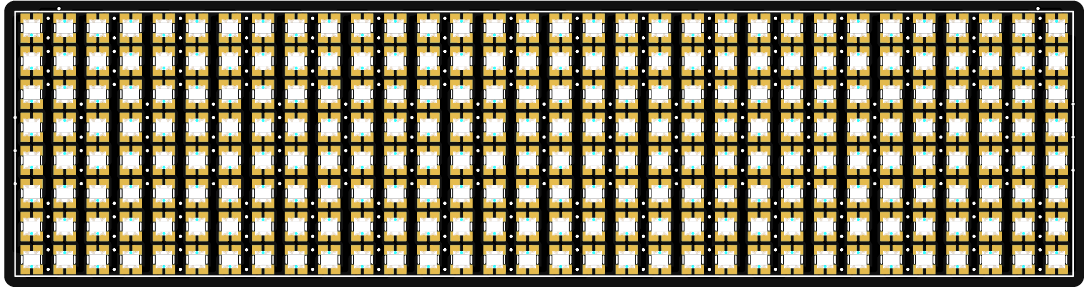
Front View of Light Board; Back View of Light Board (Components on the Back of the Board Do Not Require Soldering in This Project; The Light Board Has 6 M1.2 Copper Pillar Pads Reserved for Further Expansion);

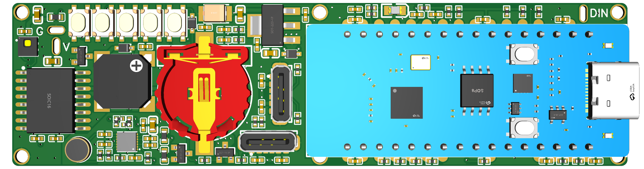
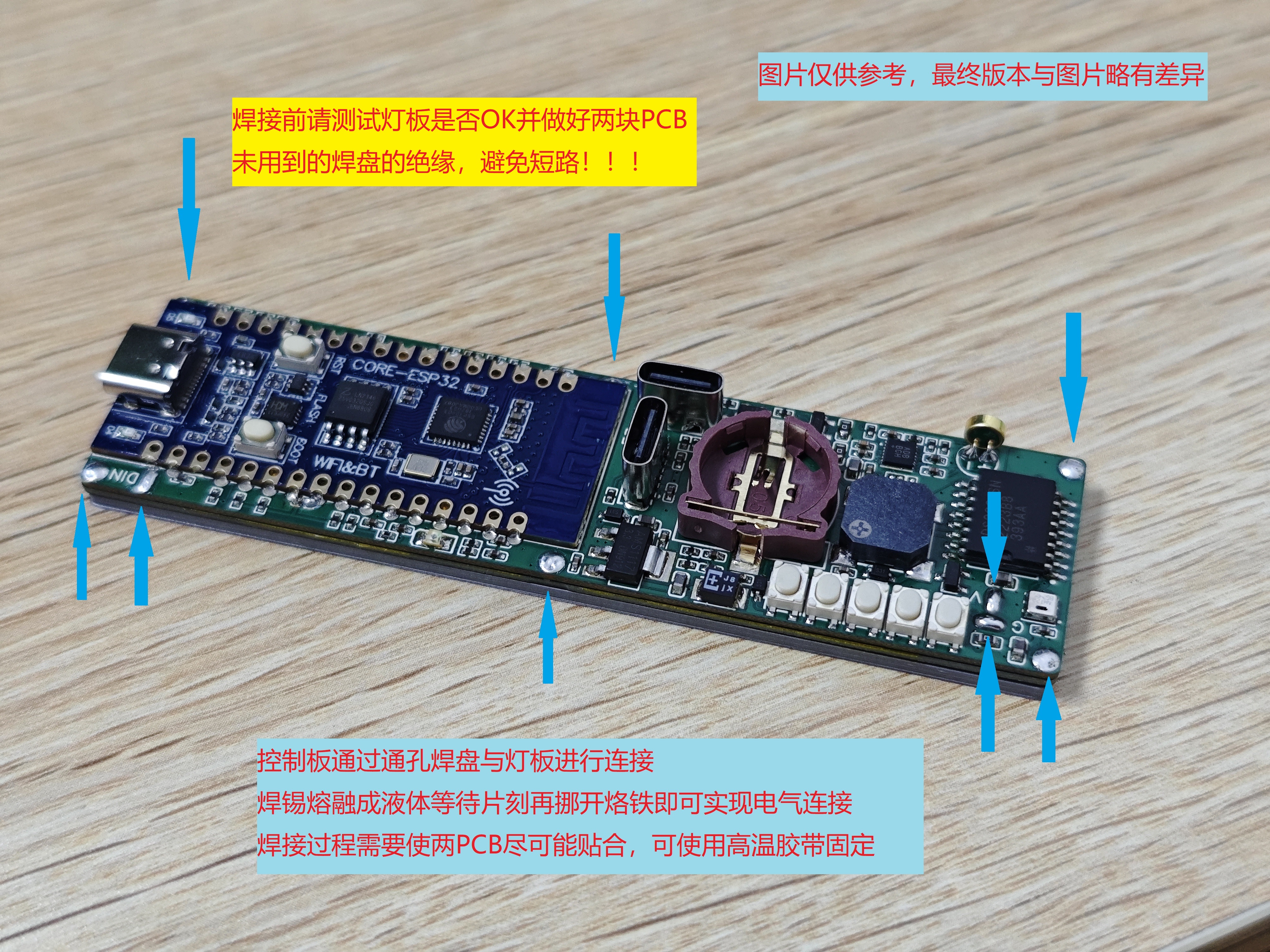
3D View of Control Board (Subject to Actual Product);
SMD Photoresistor and Microphone Soldering Diagram on Control
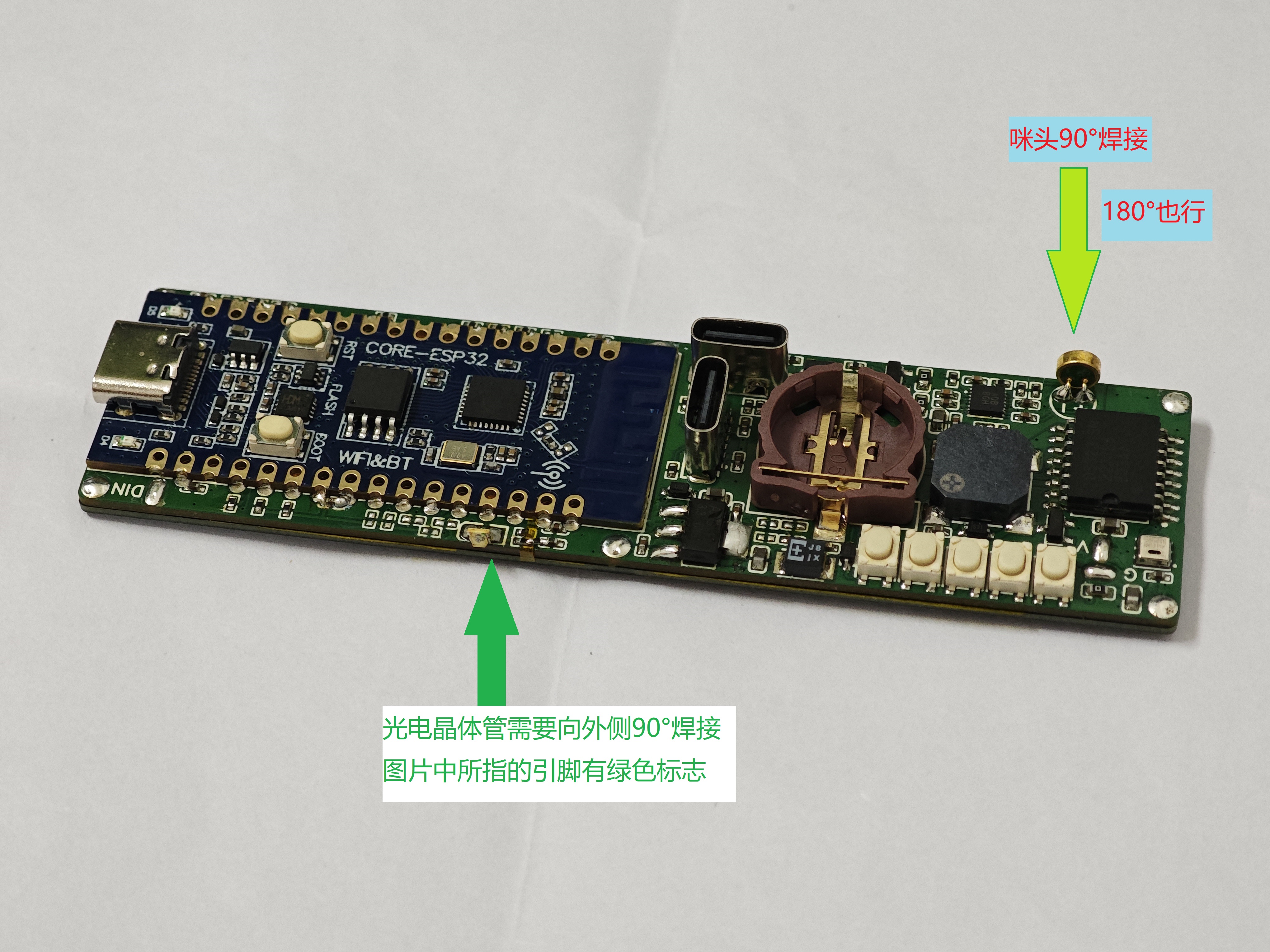
Board; Connection Diagram and Precautions for Light Board and Main Control Board (Unused Pads in the Middle Must Be Insulated).
The above is all the content regarding PCBA fabrication.
Related materials are packaged in the attachment
. Note: All PCB thickness is 1mm.


 京公网安备 11010802033920号

 MSP1N5256D-1TR


