This PD power decoy, based on CH32V003 and CH224K, allows users to select the decoy voltage and supports voltage, current, and power display.
For a pure USB ammeter project based on CH32V003 that doesn't require USB PD decoy functionality, see this link: https://oshwhub.com/wandaeda/ji-yu-ch32v003-de-usb-dian-liu-biao
Main interface:

PCB:
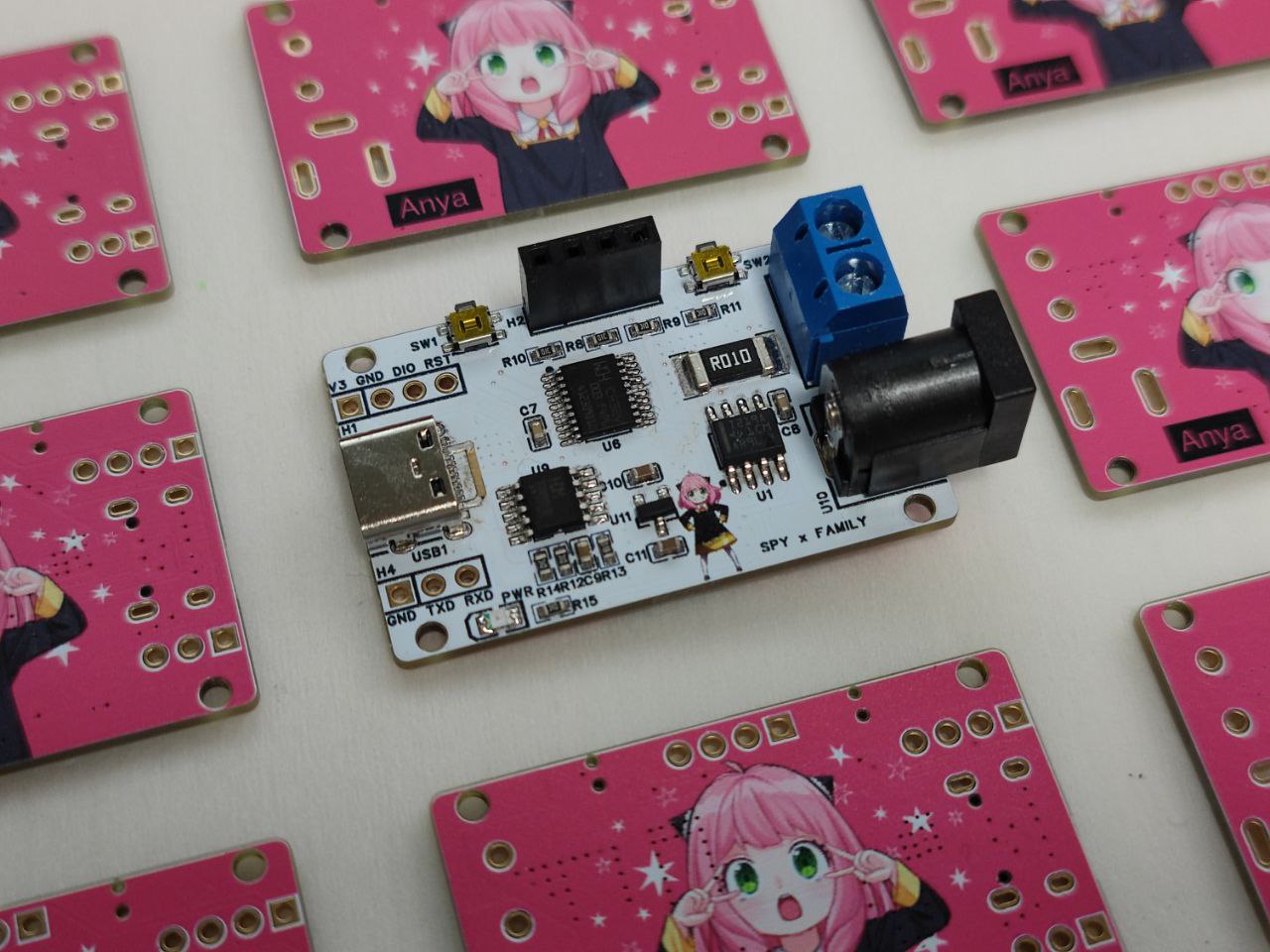
3D Monkey transparent resin shell (very nice).

USB PD decoy requires:
USB Type-C input,
DC 2.5mm and MX126 terminal output
, USB PD protocol decoy, supports multiple voltage levels, up to 20V 5A,
supports 5-20V voltage detection,
supports 0-5A current detection
, supports power calculation and capacity statistics,
supports power history chart display
, supports statistical data recording and clearing,
button switching between voltage/current data and power history charts,
uses INA219 to collect voltage and current related data,
and uses a 12864 OLED to display related data
. CH32V003 The CH32V003 series is an industrial
-grade general-purpose microcontroller based on the Qingke RISC-V2A core. It supports a 48MHz system clock frequency and features wide voltage range, single-wire debugging, low power consumption, and an ultra-small package. The CH32V003 series integrates one DMA controller, one 10-bit analog-to-digital converter (ADC), one operational amplifier comparator, multiple timers, and standard communication interfaces such as USART, IIC, and SPI.
Official website: https://www.wch.cn/products/CH32V003.html
Main parameters:
32-bit RISC-V2A processor, supports 2-level interrupt nesting,
maximum system frequency of 48MHz
, 2KB SRAM, 16KB Flash,
power supply voltage: 3.3/5V,
multiple low-power modes: sleep, standby, power-
on/power-off reset, programmable voltage monitor,
1 set of 1-channel general-purpose DMA controller,
1 set of op-amp comparators,
1 set of 10-bit ADC
, 1 16-bit advanced timer and 1 16-bit general-purpose timer
, 2 watchdog timers and 1 32-bit system time base timer
, 1 USART interface, 1 set of IIC interface, 1 set of SPI interface,
18 I/O ports, mapping one external interrupt,
64-bit unique chip ID,
serial single-wire debug interface.
Package types: TSSOP20, QFN20, SOP16, SOP8.
For this project, using the 12864 OLED and INA219 requires an I2C interface, while the buttons need to use ordinary GPIO and UART. For debugging information output, SDIO is used for programming. After comparison, the CH32V003F4P6 in TSSOP20 package is more suitable. It has more GPIOs than the CH32V003J4M6 in SOP8 package, and the UART and SDIO are not multiplexed, which better meets the needs of this project.
The MCU
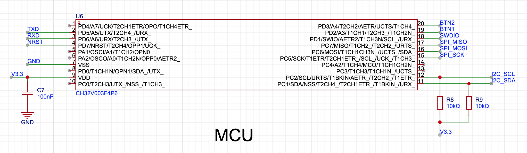
section is straightforward, powered by 3.3V with a 100nF decoupling capacitor. Note that when using I2C with the CH32V003, pull-up resistors need to be added to SCL and SDA.
Although a network identifier is added to the SPI interface, it is not actually used.
The USB Type-C input and PD output
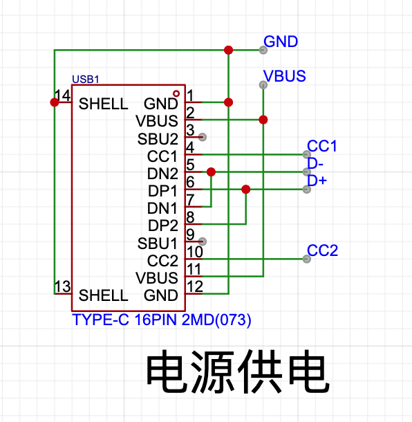
use USB Type-C 16P connectors. PD spoofing is usually not intended for re-output to USB Type-C interface devices, so the outputs here use MX126 screw-type terminals and a DC 2.5mm interface, allowing high-voltage devices to be directly connected via a DC plug or bare cable. Since the decoy itself doesn't have an external power supply,
the LDO power supply

needs to draw power from the voltage being measured. Because the measured voltage is relatively high (up to 20V in the PD protocol), a high-voltage power supply solution is required.
Compared to the previous USB ammeter, an LDO is used here to step down the input voltage to 3.3V. Since the input voltage may reach 20V, the HT7533S LDO was chosen as the step-down solution. This project uses the model from https://item.szlcsc.com/323875.html.
The overall power consumption of the MCU + OLED screen + INA219 is approximately 5mA, so there's no need to worry about the LDO's heat generation. Furthermore, compared to a DC-DC solution, it saves more components and PCB area.
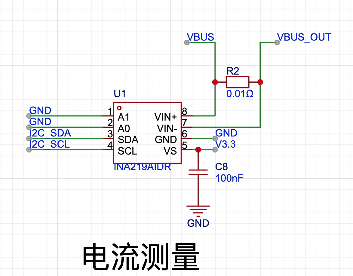
The
voltage and current measuring component used in this ammeter is the Texas Instruments INA219. It was chosen primarily because it's familiar from previous use and there are readily available libraries available.
The INA219 is a shunt and power meter with I2C or SMBUS compatible interfaces. It monitors the shunt voltage drop and bus supply voltage; the number of slews and filtering options are programmable.
The INA219 has a maximum voltage range of 26V. For PD2.0 100W, a maximum of 20V is sufficient, but it will exceed the range when using a PD3.1 140W charger with a 28V supply. However, currently, there are relatively few chargers and devices that support 140W, so this issue is not a major concern for now. The INA226, with its higher range, can be considered as a replacement in the future.
To measure relatively high voltages and avoid excessive heat, a 10mR sampling resistor is used. This results in a power consumption of only 0.25W even at 100W 20V 5A, and in actual testing, it did not overheat during prolonged 100W operation.
The ammeter
uses a common 0.96-inch 12864 OLED screen as its display device. This screen is relatively easy to operate and consumes relatively little power, making it suitable for this scenario. Furthermore, since a bare 0.96 OLED screen requires complex supporting circuitry, a pre-made screen module is used here to simplify manufacturing. It is soldered onto the PCB using header pins.
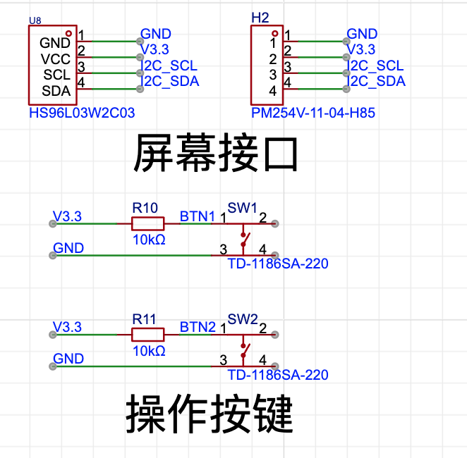
The 2.54mm header pin height allows the screen to maintain a certain distance from the PCB without pressing on the MCU or other components. Note that U8 and H2 share the same interface; U8 is placed primarily for positioning and alignment.
The button uses a standard side-press design, triggered by a low-level signal.
Download and Debugging
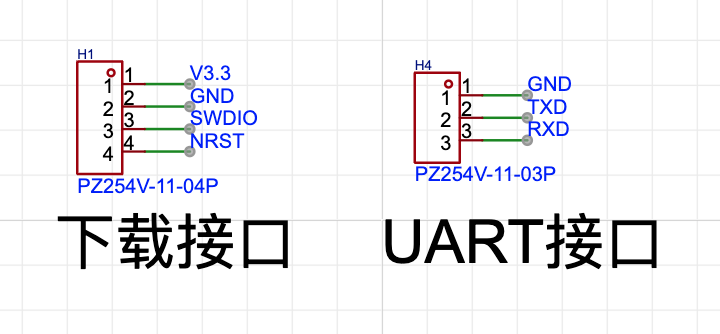
Note that the CH32V003 series requires a WCH Link-E programmer. In actual use, only V3.3, GND, and SWDIO need to be connected to program the device. If the ammeter's Type-C input has power, only GND and SWDIO need to be connected for programming.
The casing and panel
are printed using 3D Monkey printing service, using transparent resin material with a spray-painted finish, giving it a transparent texture – essentially a transparent exploration edition!

Since color silkscreen printing was used, the design had to be visible, making a transparent casing more suitable.
The ammeter program is essentially
an infinite loop that reads voltage and current, calculates power and capacity, and displays the results.
The I2C and 12864 OELD driver code references the implementation at https://github.com/wagiminator/CH32V003-GameConsole.
Actual testing showed a screen refresh rate of approximately 40 FPS, meaning voltage and current are sampled 40 times per second.
The power history curve is displayed using the average value per minute, with 128 points horizontally, meaning it can display a total of 128 minutes of power history, which is sufficient for most usage scenarios.
Postscript
: Compared to the previous USB ammeter based on the CH32V003, this USB PD decoy replaces the DC-DC converter with an LDO and adds the CH224K chip for USB PD voltage decoy, achieving a completely different function.
Finally, thanks to JLCIC's "Warm Winter Creation" event, which provided free PCB prototyping, 3D printing, and component purchases, ultimately enabling the completion of this project. JLCIC's industry service group is incredibly helpful for individual enthusiasts, making personal product development entirely possible, and the JLCIC open-source platform is a fantastic community with various projects for reference and learning.


 京公网安备 11010802033920号

 EB51F4D15DN-12.800M-CD


