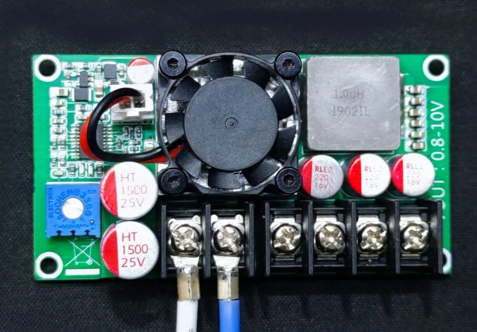
Project Introduction:
LM5117 External Switch High-Efficiency, Low-Ripple Buck Module.
Project Function:
Converts a fixed 12V input voltage to an adjustable voltage.
Project Parameters
: Uses the LM5117 BUCK chip as the main controller, achieving up to 97% efficiency and capable of continuous 20A high-current output.
Input: 12V; Output: 0.8V-10V; Maximum Output: 24A. If the current exceeds this, it enters CC mode (non-adjustable).
Features undervoltage protection: If the input is below 10.8V, it enters protection mode and stops working; otherwise, it continues to operate.
Principle Analysis (Hardware Description)
: SEPIC Regulated Power Supply Section :

This section mainly regulates the chip's voltage and provides stable power
to the fan, stabilizing the input voltage below or above 12V to 12V.
Main Control and Switching Power Section:
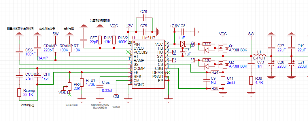
Basic DC-DC knowledge is sufficient; those unfamiliar can search online. Component Selection: Field-Effect Transistor
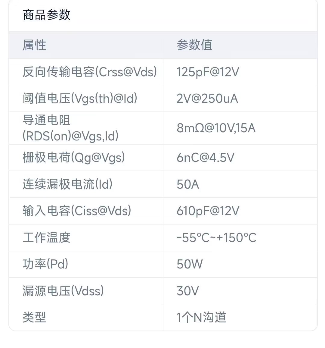
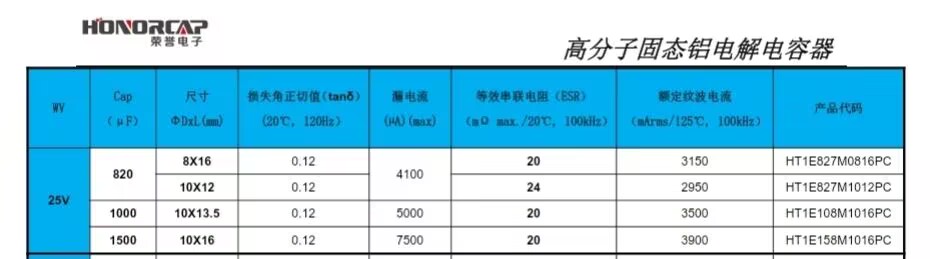
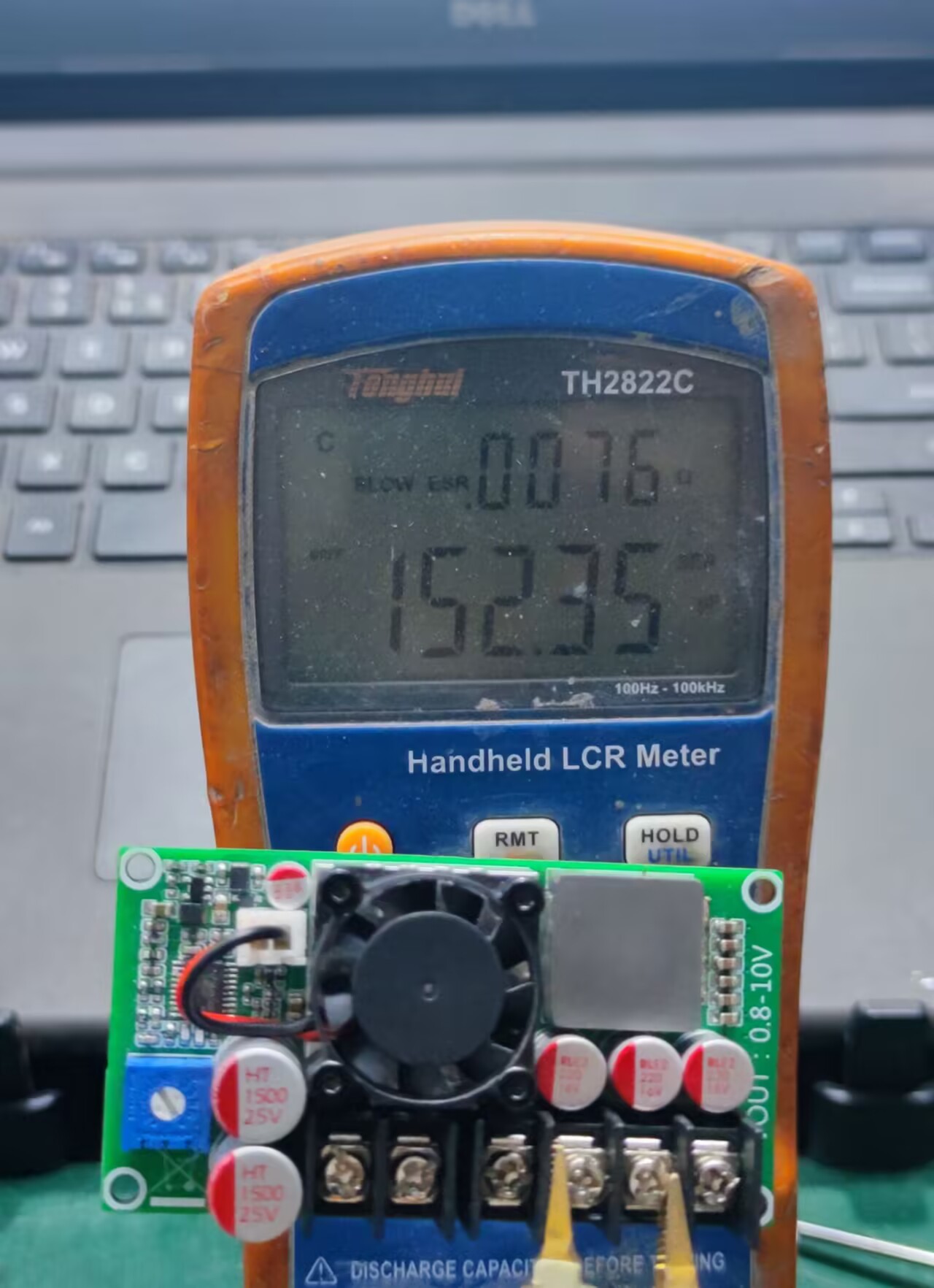
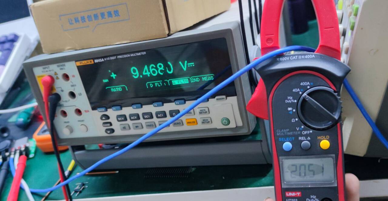
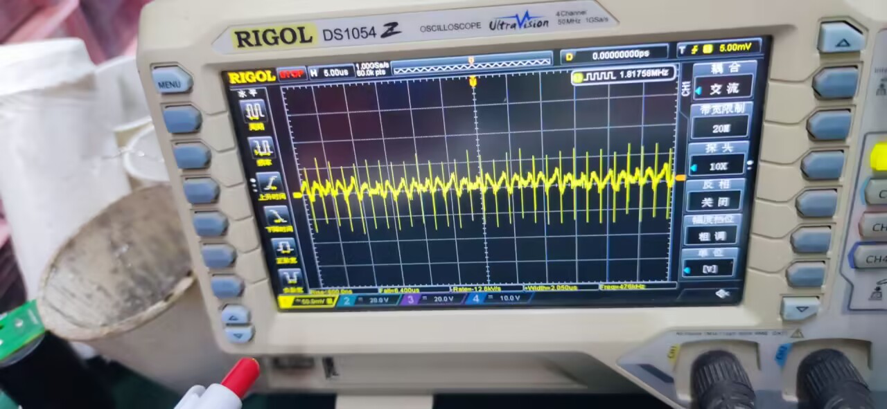
Selection : This module uses the domestic brand Renmao's MOT50N03D field-effect transistor. Qg and Ciss are extremely small, allowing for high-frequency use. The driving frequency is 480kHz. Those unfamiliar with selection should not easily replace with other models; if it cannot be driven and remains in the linear region, it will explode. The gate current-limiting resistor is 4.7R. 0603 Resistor Output Voltage Calculation: VOUT = Verf * (1 + R1/R2) Verf = 0.8V R1 is the pull-up resistor, and R2 is the pull-down resistor. Note that the pull-down resistor should not exceed 25K, as this can easily lead to loop instability. Input Capacitor Selection: Due to the large output current, the calculated input ripple current is approximately 13A. Therefore, a large-capacity, low-internal-resistance input capacitor should be selected. Use high-quality solid-state capacitors in conjunction with MLCC capacitors to suppress the input ripple voltage and avoid interference with other circuits. Use two 25V 1500uF (10*16mm) capacitors in conjunction with six 25V 22uF capacitors. The 0805 ceramic capacitor bridge at 100kHz measures the input capacitor with an ESR of only 9.5 milliohms. The selection of the output capacitor is generally the same as the input capacitor, but the feedback compensation circuit must be considered. Therefore, the capacitor value should not be too large, otherwise the circuit feedback response will be slow. Three 16V 220uf (8*9) capacitors are used in conjunction with six 10V 22uf capacitors. The 0805 ceramic capacitor bridge at 100kHz measures the output capacitor with an ESR of only 7.6 milliohms. The heatsink and fan are 2507 specification, 12V power supply, 16000 RPM, 0.12A. Ball bearings are preferred for lower noise. The wires should be shortened upon arrival. Note the positive and negative terminals. The heatsink is 25x25x6mm with a hole spacing of 20mm. Ripple measurement: Input 11.8V, Output 9.46V, 20A ripple 30mV, no-load ripple below 10mV.


lm5117 calculation file.xls
lm5117.pdf
VID_20241013_205007(1).mp4
PDF_LM5117 step-down module.zip
Altium_LM5117 step-down module.zip
PADS_LM5117 step-down module.zip
BOM_LM5117 step-down module.xlsx
91591
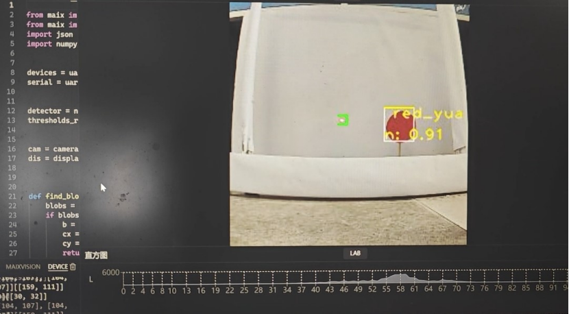
Laser vision recognition system
Laser target shooting device based on CAM vision module
The requirements for
the laser target shooting system are: 1. The system should accurately identify targets generated by a randomly generated gimbal, with an accuracy rate exceeding 90%.
2. The system should accurately hit the target, with a maximum of three hits per target. 3. The main system should be able to handle communication data from
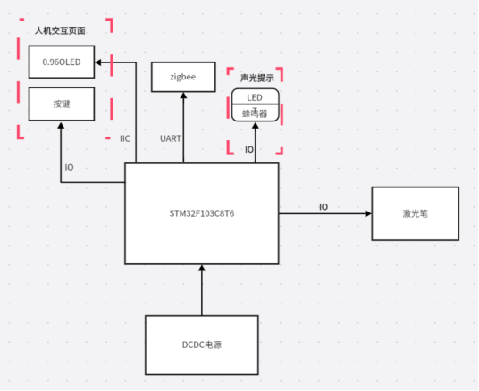
multiple subsystems . The system consists of a main system and multiple subsystems. The main system is a vision-based laser target shooting system, while the subsystems are a random target generation gimbal system and a manual target shooting laser gun system. These subsystems operate around the main system, with one-to-many communication. The main idea of this system is that the random target generation system generates the targets to be shot. The main system, acting as the terminal decision-maker, uses a human-computer interface to determine whether to automatically track and shoot the target or use it for laser gun scoring. The system construction involves a vision processing platform acquiring data, the main system's human-computer interface deciding whether to automatically shoot or manually score the target, and the random target generation system generating the targets to be shot. The schematic design describes the motion control system, which uses an SG2002 SOC running a Linux+RTOS system with Maixpy as the vision processing platform and an STM32F407VET6 microcontroller to control the servo gimbal's movement. Data is collected by a GC465 sensor and transmitted to the SG2002. Maixpy, running on the SG2002, uses the YOLOv5s algorithm and the Lab color space to capture color blocks for identification and returns data on targets and red dots. This data is then transmitted to the microcontroller via serial port. The STM32F407VET6 uses two one-dimensional closed-loop position PID controllers to form an angle loop, outputting two PWM signals to achieve the control effect. A TFT-LCD screen and buttons provide a human-machine interface for function selection. LEDs and a buzzer provide audible and visual alarms, and Zigbee enables wireless communication. The random target generation gimbal uses an STM32F103C8T6 microcontroller to control the servo and generate random targets. Nine different objects are generated by outputting nine PWM signals. An OLED screen and buttons are used for the human-machine interface to select functions, LEDs and a buzzer provide system operation indicators, and a Zigbee module enables wireless data transmission and reception. The laser gun uses an STM32F103C8T6 microcontroller to control a servo motor to generate random targets. An OLED screen and buttons are used for the human-machine interface to select functions, LEDs and a buzzer provide system operation indicators, and a Zigbee module enables wireless data transmission and reception. Software description from maix import camera, display, image, nn, app from maix import uart import json import numpy as np devices = uart.list_devices() serial = uart.UART(devices[0], 115200) detector = nn.YOLOv5(model="/root/models/model-150813.maixcam/model_150813.mud") thresholds_redyuan = [[20, 100, 127, 10, -128, 127]] # cam = camera.Camera(detector.input_width(), detector.input_height(), detector.input_format()) dis = display.Display() def find_blob_center(threshold): blobs = img.find_blobs(threshold, x_stride=1, y_stride=1,area_threshold=0,pixels_threshold=0) #Find color blocks if blobs: b = blobs[0] cx = b.cx() cy = b.cy() return cx, cy return None, None while not app.need_exit(): img = cam.read() data=[] data_one=[] data_two=[] data_three=[] tesu = 0 blobs_red = img.find_blobs(thresholds_redyuan, pixels_threshold=1) #Find red color blocks if blobs_red:#Red needs special handling for i in range(len(blobs_red)):#Find the length of the array arr = np.array([blobs_red[i].h()]) min_idex = np.argmin(arr) if blobs_red[min_idex].density() > 0.7: #Filtering #print('The duty cycle of this shape is',blobs_red[min_idex+1].density()) img.draw_rect(blobs_red[min_idex-1][0],blobs_red[min_idex-1][1],blobs_red[min_idex-1][2],blobs_red[min_idex-1][3], image.COLOR_GREEN) data.append((blobs_red[min_idex-1][5],blobs_red[min_idex-1][6])) #print("dorp:",data) objs = detector.detect(img, conf_th = 0.5, iou_th = 0.45) #Find the shape for obj in objs:


img.draw_rect(obj.x, obj.y, obj.w, obj.h, color = image.COLOR_YELLOW)#Frame out
obj_cx = (obj.x + obj.w + obj.x) // 2
obj_cy = (obj.y + obj.h + obj.y) // 2
data_one.append((obj_cx,obj_cy))
data_three.append((obj.w,obj.h))
msg = f'{detector.labels[obj.class_id]}: {obj.score:.2f}'
img.draw_string(obj.x, obj.y, msg, color = image.COLOR_YELLOW)
#print(detector.labels[obj.class_id])#Display the recognized objects
#print(type(detector.labels[obj.class_id]))
if detector.labels[obj.class_id] is not None:#non-empty
if detector.labels[obj.class_id] == "blue_yuan":#non-empty
data_two.append((1))
elif detector.labels[obj.class_id] == " blue_juxing":#non-empty
data_two.append((2))
elif detector.labels[obj.class_id] == " red_juxing":#non-empty
data_two.append((3))
elif detector.labels[obj.class_id] == " red_sanjiao":#non-empty
tesu = 1
data_two.append((4))
elif detector.labels[obj.class_id] == " green_yuan":#non-empty
data_two.append((5))
elif detector.labels[obj.class_id] == " bule_sanjiao":#non-empty
data_two.append((6))
elif detector.labels[obj.class_id] == " green_juxing": # Not empty
data_two.append((7))
elif detector.labels[obj.class_id] == " green_sanjiao": # Not empty
data_two.append((8))
elif detector.labels[obj.class_id] == " red_yuan": # Not empty
data_two.append((9))
data_out = json.dumps((data))
data_outone = json.dumps((data_one)) # Send the coordinates of the identified object
data_outtwo = json.dumps((data_two)) # Send the shape of the identified object
data_outthree = json.dumps((data_three))
print(data_out+data_outone+data_outtwo+data_outthree+'
')
if tesu != 1 :
serial.write_str(data_out+data_outone+data_outtwo+data_outthree+'
')
print("good")
elif tesu == 1:
serial.write_str(data_outone+data_outone+data_outtwo+data_outthree+'
')
print("bed")
dis.show(img)

Physical display instructions


suiji(1002).zip
jiguangqiang(1002).zip
mmexport1728287101277.mp4
PDF_Laser Vision Recognition System.zip
Altium_Laser Vision Recognition System.zip
PADS_Laser Vision Recognition System.zip
91592
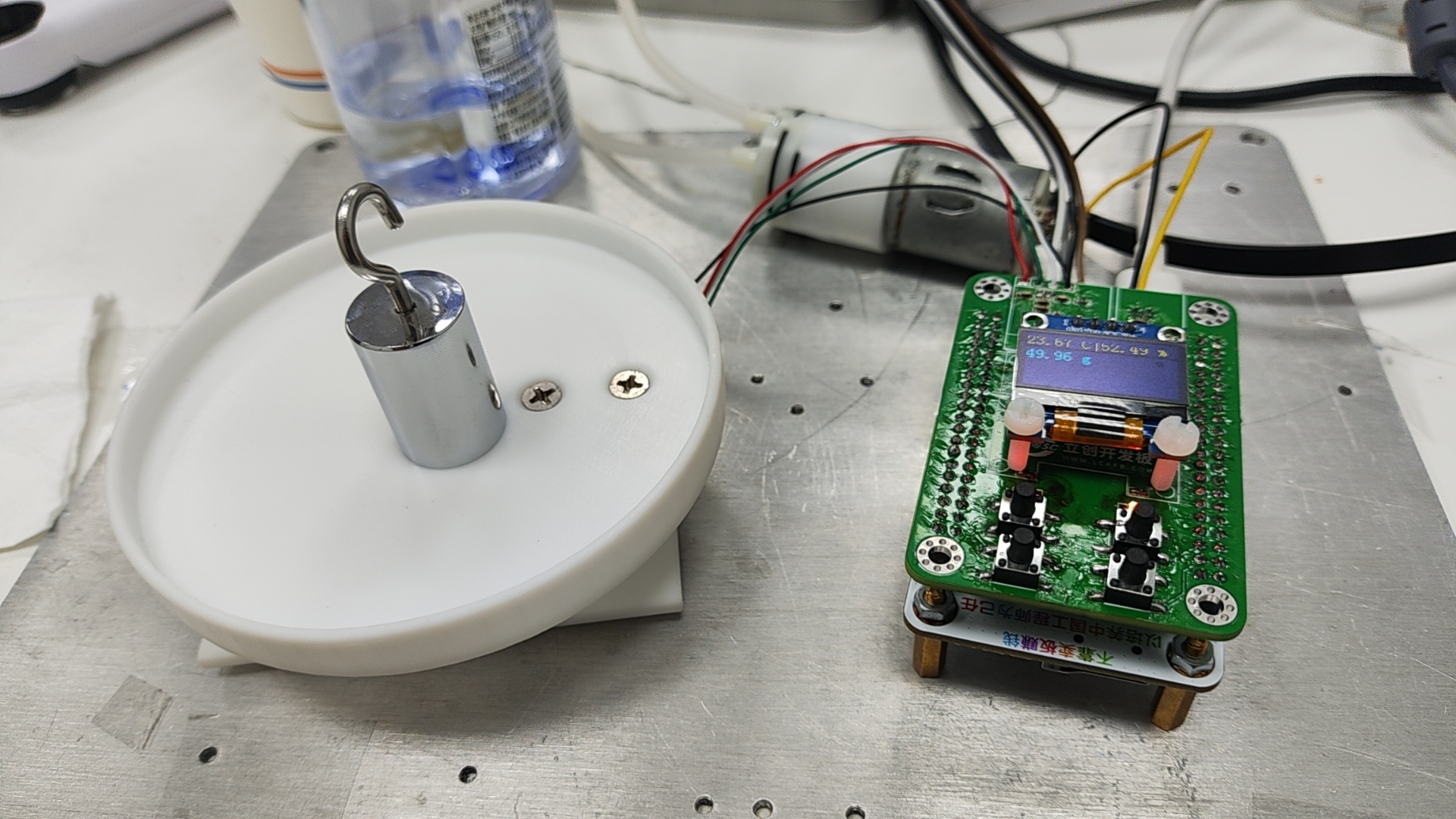
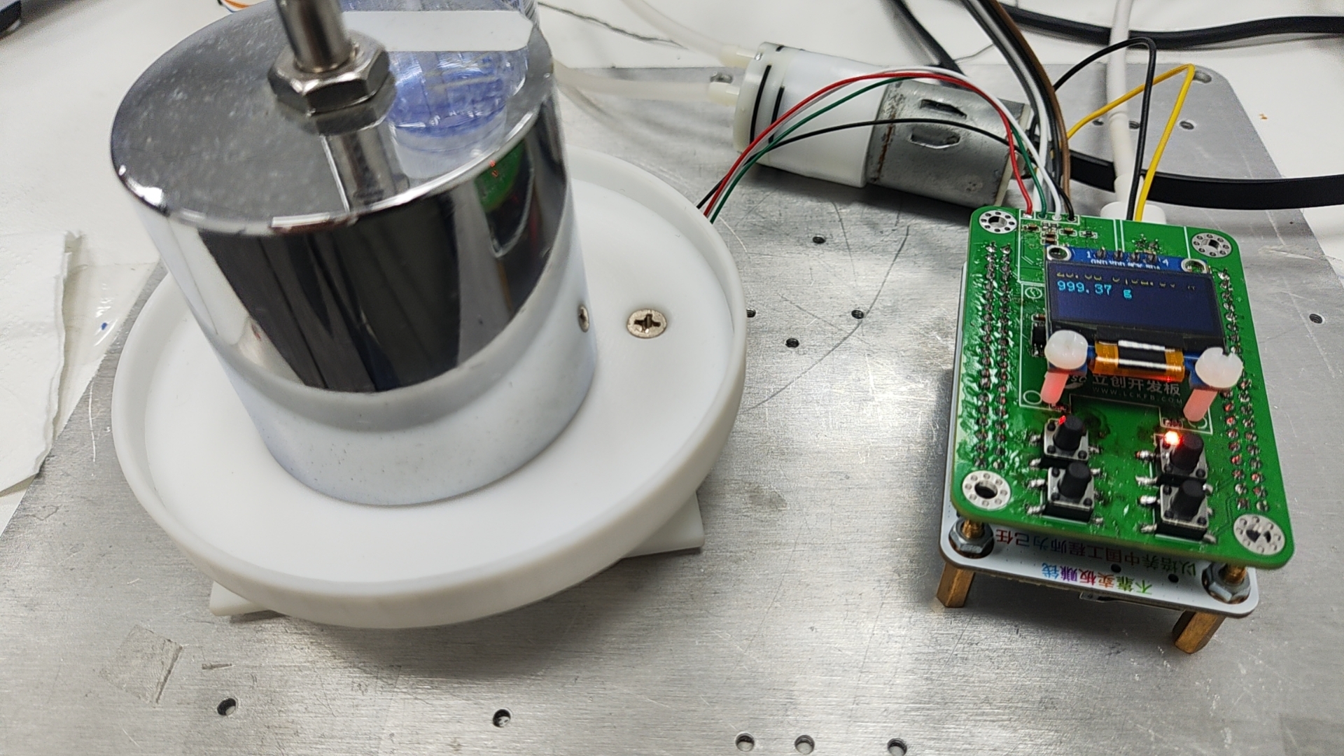
High-precision electronic scales
It can achieve precise measurement of weight from 0-1000g with an accuracy of 0.3g by connecting an external ADS1232, and also has a quantitative filling function.
Project Introduction:
This project is an extension of the SkyStar development board, incorporating an AD1232 for acquiring bridge strain output to measure weight. The weighing range is determined by the bridge and the hardness of the scale body.
Project Functions
: The main project functions are as follows:
weighing
ambient temperature measurement (zero-point offset compensation)
and quantitative liquid filling.
Project Parameters :
Development environment: Cube IDE 1.8
SkyStar Youth Edition STM32VGT6
; ADC: ADS1232;
Temperature sensor: SHT20;
Motor driver: RZ7889 ;
Display: 0.96-inch OLED IIC driver
. ...
Notes:
Do not use the latest Cube IDE software version, otherwise, downloading component packages may require login, leading to download failures. It is highly likely that the program will not be able to log in.
First, solder the SHT20 temperature sensor using a heating plate. Do not use an air gun to heat this part!
Do not connect the motor immediately after powering on, as this may cause malfunction.
Button functions include
weighing zeroing,
automatic filling (50g) ,
and
retaining
the current weight after powering on.
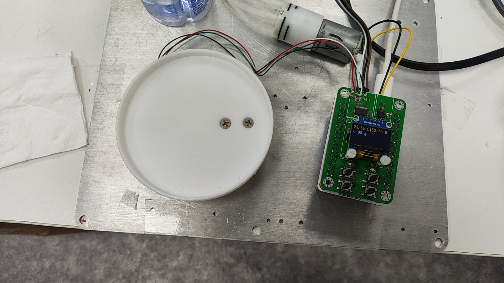
Place a 50g weight on the scale.
Place a 1000g weight on the scale.
Attachments include:
demonstration video (.mp4), automatic filling demonstration video
DEMO2.zip, cube IDE 1.8 engineering
upper tray (.STL), scale body upper tray
bottom (.STL), and scale body lower tray. Purchase details:
The motor is faulty; the bridge sensor removed from the water flosser
can be purchased directly from Taobao: https://item.taobao.com/item.htm?abbucket=12&id=761644062665&ns=1&pisk=gjUrLTTHSaQP_-bsGj3E_OzUsvu-74X1zyMItWVnNYDoFWcn8-2CwYNheJzEnWE5wD6JTQU4QeT5egFH82g hCO_157FSJ2X6CdvMTLhZOpbIEXv0w0AAGZ_157F2Nbf_iNaSVWvjsHY3K0mmmXHDZLD3KqYmNxYotUcHnslKn2Yk-DYmo Xhe-LDuKKxmOfTH-2cnmncZ_2D3K2cbd7VHufil13Dahq-BC0DgZx8H7ChrqW7tHev3obPqI7xp-e4qa04CjmQVr0Z36cU7 Nw8xP5rmobyhST00soPs4zWwPvnUu8rUF6tKgkP3W43wtaVqzYogz0dpyRV4tli4l1btz4DuA4FB_TN4z8N8uWOHm4u70c zrSNpodoNa8XzdpZyaZl23YgzMpj2QiyEyKHooMjk1gsrgTpevMgQKfHKKmVhqC_GWvHnoMjk1gs-pvmDxgA1SN&priceT Id=2147807f17292617752603959e640f&skuId=5421332955116&spm=a21n57.1.item.2.acce523cr6by94&utparam=%7B%22aplus_abtest%22%3A%2286a2fbdb6aafa1a19426dc48c77b4e17%22%7D&xxc=taobaoSearch
The scale body is fixed with a countersunk head, M4 2 M5 2, and the length should be 12mm
. A 5V motor is sufficient.
Demo video, .mp4
DEMO2.zip
Upper tray.STL
Bottom .STL
PDF_High-precision electronic scale.zip
Altium_High Precision Electronic Scale.zip
PADS_High Precision Electronic Scale.zip
BOM_High-precision electronic scale.xlsx
91593
FG927 E-ink GPS Cyclist
This is a GPS cycling computer based on an e-ink screen, which can also be used to display images of Amane Suzuha.
The FG927 is an e-ink GPS cycling computer.
First, I want to clarify that I share the same birthday as Lingyu, hence the name of this project: FG927. Because it uses the ESP32H2, it's the ver. ESP32H2. This is a demonstration video
of an e-ink GPS cycling computer project. Features to be added include: GPS-based speed display (one decimal place); magnetometer-based cycling direction corrected by GPS; gyroscope-based hill-climbing angle (not very useful, it flies over speed bumps); single-trip average speed, single-trip top speed, single-trip mileage, single-trip riding time, total mileage; average speed and top speed statistics over the past twelve hours (accurate to the minute); night vision lighting (brightest enough to be used as a flashlight); GPS-corrected UTC+8 time ; single-trip calorie calculation (assuming you weigh 70kg); temperature, air pressure, and altitude; automatic standby after 4 minutes of stopping, automatically waking up upon monitoring vehicle movement; approximately nine hours of battery life (shorter with lights on); low battery standby (about a week from when it can't be turned on to when it's completely out of power); 128Mb. The cycling route recording function, composed of flash and BLE (to be developed), displays images of Suzuha. Key hardware used includes: MCU: ESP32-H2-MINI-1 ; Gyroscope: ICM20948; Power Management: AXP2101 (DC-CDC1 default voltage must be 3.3V!!!) ; Barometer: MS5611 ; LED Management: LP5009; E-ink Screen: GDEY0154D67; GPS: ATGM336H-5N31; Flash: W25Q128JVPIQ (unused) ; Power Meter: INA219; LCD screen compatible with ST7789, but no matching casing; 3D modeling file; 603035 600mAh lithium battery; Ceramic Antenna: BWGPSCNX18-18B1. The GitHub repository and 3D printing files are available at https://github.com/Evil-Ender/FG927. The shell cover is printed in two colors, but it's not a big problem if it's not. The layer height is 0.08mm. I haven't tried other methods to see if they would work. In short, being precise is never a bad thing, as it doesn't need to withstand any huge strain. There are two types of brackets: one extends out and requires assembly, and the other sits on the handle. You can print them according to your preference. It's best to use materials with a high glass transition temperature, such as ABS; PLA might bend after being exposed to sunlight. You will need to prepare M5 screws and nuts, as well as M3 knurled nuts (3mm high, 4mm outer diameter), M3 flathead screws (5mm high, 6mm head diameter, 0.8mm thickness), and M3*8 hex socket screws. Debugging requires an ESP32 development board library version 3.0 or higher to compile the ESP32H2 files. Please be aware of this. To test the success of the soldering, you can uncomment the `#define D_BUG` line in `BIANCHI.h` to receive error data from the serial port (error messages other than those indicating communication failure are quite messy). You can use the included `pic_gen.py` to convert a 200*200 image into a grayscale image suitable for e-ink displays; remember to adjust the threshold according to the image's style.
PDF_FG927 E-ink GPS Cyclist.zip
Altium_FG927 e-ink GPS computer.zip
PADS_FG927 e-ink GPS computer.zip
BOM_FG927 E-ink GPS Cyclist.xlsx
91594
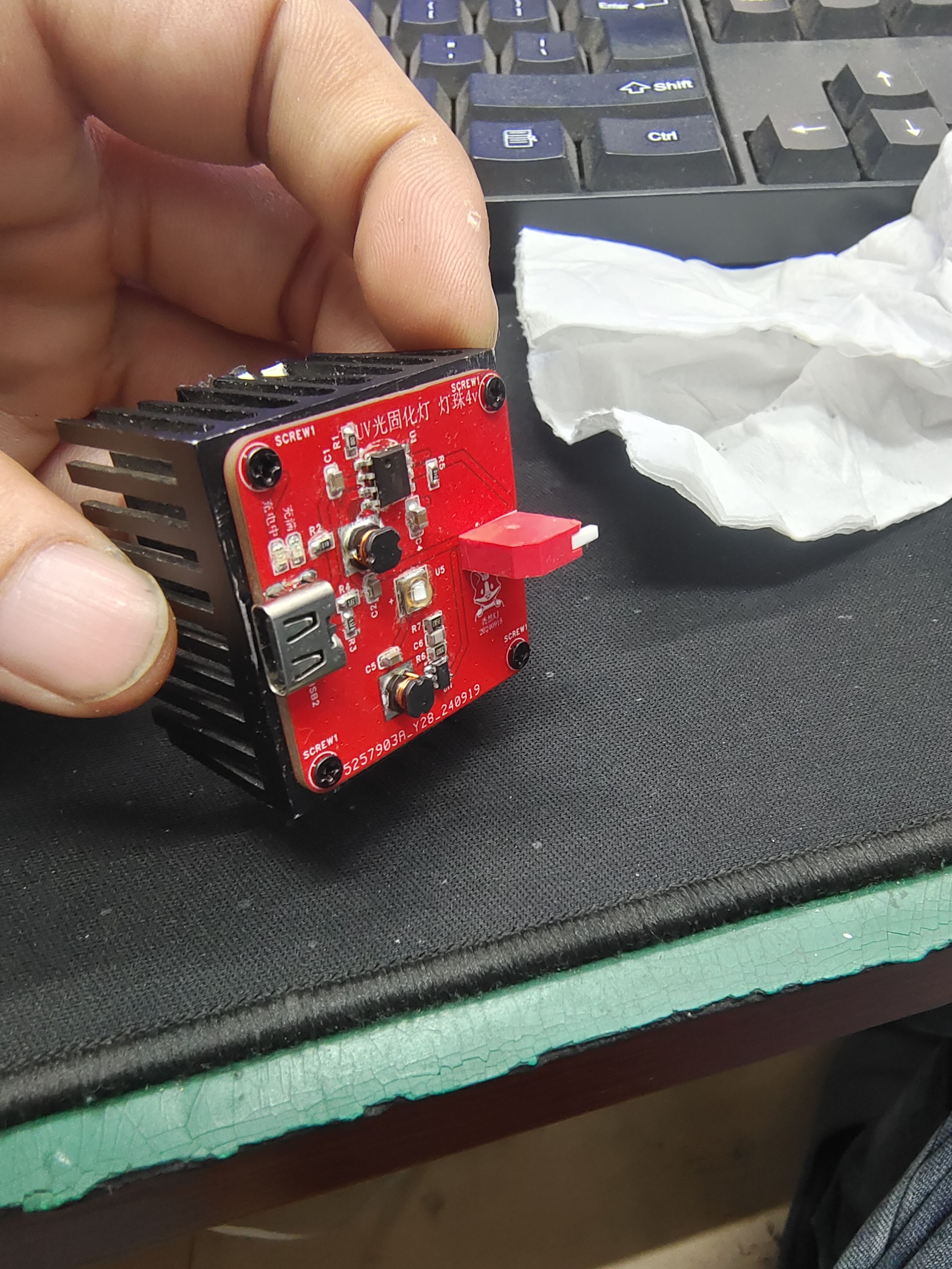
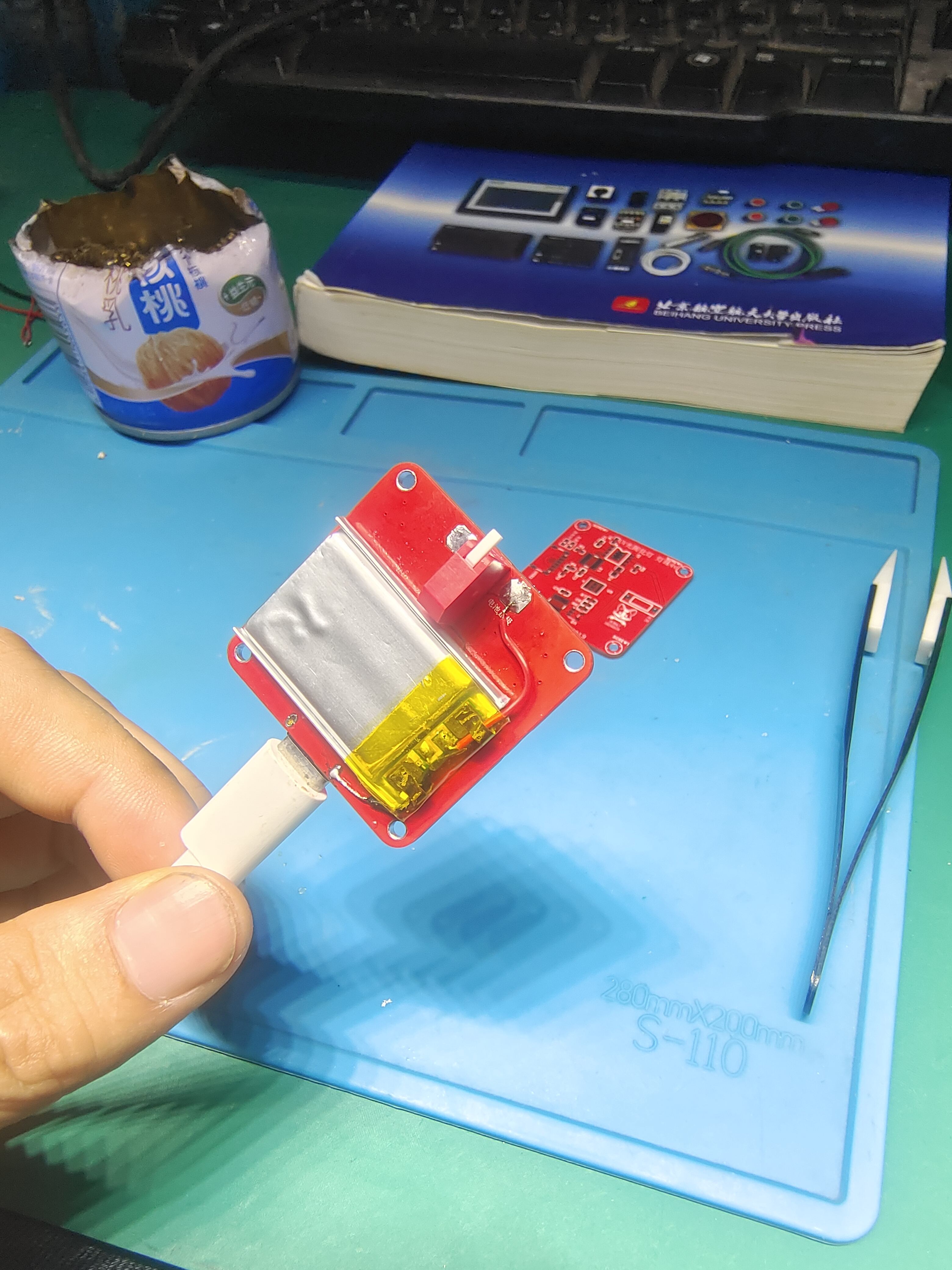
4V rechargeable UV curing UV lamp, portable mobile phone repair, find scorpion-shaped mark finder, quick-drying adhesive.
This small, portable UV lamp features a Type-C rechargeable portability and measures only 35*35mm, allowing for a very small casing. It uses
an ETA9697 5V to DC-DC charging chip and a TI Texas Instruments TLV62568DBVR 4V voltage driver for the LED beads.
I was bored and saw that no one had done this before. I thought the ones on the market were too expensive, but I had some spare parts, so I figured I could tinker with them and make something.
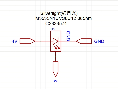
I used Silverlight 4V LEDs M3535N1UVS8U12-385nm (note the LED orientation). The manufacturer's datasheet seems to have a problem with the package;
see my schematic below. The LED doesn't light up, so I connected the pins like this.
The finished product looks pretty good, as you can see in the video. The green solder mask cured quickly
, and my partner used it for manicures; the nail polish dried quickly.
The manufacturer's datasheet says this LED can draw up to 700mA, so the heat generation is indeed quite high. For portability, I swapped the EN switch pins to insulate
the positive and negative terminals, and connected it to the southbridge heatsink with thermal paste.
This allows it to work for a long time, but I'll have to find a way to modify the PCB and redraw the battery.
I'm a complete beginner . The circuit is for reference only.
If any experts have better solutions, please share them.
All of the above is open source.
Personally, I think it's quite enjoyable to open source something similar.
Before, I only watched others open source
, but now with such a great platform as LCSC, everyone can unleash their potential and easily try things that were unthinkable before.
Thanks to LCSC for providing such a great platform
! Let's exchange ideas!
be5055c0fc13bac7a02d4e3e219e8ba7.mp4
PDF_4V Rechargeable UV Curing Ultraviolet Lamp Portable Mobile Phone Repair Tool for Finding Scorpions and Marks, Quick-drying Adhesive.zip
Altium_4V Rechargeable UV Curing Ultraviolet Lamp Portable Mobile Phone Repair, Scorpion Spotting, Mark Finding, Quick-drying Adhesive.zip
PADS_4V Rechargeable UV Curing Ultraviolet Lamp Portable Mobile Phone Repair, Scorpion Spotting, Mark Finding, Quick-drying Adhesive.zip
BOM_4V Rechargeable UV Curing Ultraviolet Lamp Portable Mobile Phone Repair, Scorpion Spotting, Mark Finding, Quick Drying Adhesive.xlsx
91596
Two-string supercapacitor spot welding machine
Two-string supercapacitor lithium battery spot welding machine
This is the second time I've made a spot welder for two strings of supercapacitors. The results are better than the first time. The test used 0.2mm nickel steel strip stacked with 0.1mm copper strip, and the effect was acceptable; as long as it works, it's fine. The main controller is a PY32F030F28P6, which accurately measures the voltage of each capacitor string. The second capacitor string is measured using a differential amplifier circuit, and a BW6101 is used for voltage clamping (passive balancing). A thermistor and cooling fan are used to dissipate heat from the clamping circuit. Automatic triggering and limit switch triggering both work. The display can be a 12864 OLED; just modify the pins and initialization program to simulate SPI. Charging is done using a power chip connected in series with a cement resistor.
I had many complaints about the passive balancing. Later, I tested the "Three-String Active Balancing Mini Version" open-source project, which seemed very useful; I might modify it later.
Test video link: [QQ Short Video] DIY enthusiast Luo's work https://s.xsj.qq.com/NatO1nlk Click the link to view directly
[VID_20241010_175825-Bilibili] https://b23.tv/CFmWNxB
PY32F030F28P6 - Simple Test Example for Two-Series Supercapacitor Spot Welding Machine.zip
PDF_Two-Series Supercapacitor Spot Welding Machine.zip
Altium_Two-Series Supercapacitor Spot Welding Machine.zip
PADS_Two-Series Supercapacitor Spot Welding Machine.zip
BOM_Two-Series Supercapacitor Spot Welding Machine.xlsx
91600
Arduino Uno 3D Printed Shield with Raspberry Pi Extended Cap and Simple Screen
A 3D-printed shield compatible with the Arduino Uno, an extension cap compatible with the Raspberry Pi Zero, and a replica of a simple screen.
Compatible with small 3D printers such as the Voron 0 using Klipper firmware.
The 3D-printed shield is just enough to build a Voron 0 with the most basic functions. If you want to add more interfaces, you'll need to use it with a Raspberry Pi expansion cap. Connecting two printed shields should also work if you're using Klipper.
The V0 Simple Display has also been redrawn, using the same component positions for compatibility.
The 3D-printed shield
design is inspired by Protoneer's CNC Shield and the RepRap project's Arduino Mega Pololu Shield (RAMPS) (perhaps this board could be called the Arduino Uno Pololu Shield?).
This expansion shield is designed for use with the Arduino Uno R3, but theoretically it should be compatible with any development board using Uno-sized sockets. Many official MCU development boards support the Arduino pin layout (such as Renesas and STMicroelectronics).
To be compatible with both 3.3V and 5V development boards, it is powered via the IOREF interface on the Uno R3. This interface may not be present on some very old Uno development boards, so the external power input pad in the upper right corner can be used.
Development boards using Type-B interfaces (large square pins) may experience interference with MOSFETs. However, many Uno boards now use Micro-B or Type-C. Slightly moving the soldered MOS positions might eliminate interference. If that doesn't work, you can remove the Type-B interface and communicate directly using the Arduino's serial port (pins 0 and 1).
This design is primarily for Klipper, but other programs should also be compatible.
The TMC2209 stepper motor driver module is highly recommended. To save I/O, the En pins of all stepper motor drivers are fixed to GND to make them default to the ON state. The TMC2209 can control the driver's on/off state via a single-wire serial port instead of the En pin, so it can be turned off when not in use.
Additionally, the 3D printed shield does not have a power supply function, so separate power supplies are needed for the development board and Raspberry Pi. The 3D printed
shield's I/O interfaces are as follows:
Arduino Uno size-compatible header;
4 sockets compatible with Pololu stepper motor driver module pins;
2 heater interfaces;
2 fan interfaces;
3 limit switch interfaces (multiplexed with soft limit) ;
2 thermistor interfaces
. Please refer to the silkscreen on the PCB for the specific location of each interface.
Jumper settings
at the stepper motor driver location control functions such as microstepping and serial port control. The jumper numbers are as follows:
10
7
4
1
11
8
5
2
12
9
6
3.
Jumpers 6 and 3 are soft limit jumpers, jumpers 12 and 9 are serial port jumpers, and the remaining positions have different functions depending on the driver module used.
Using the serial port to control the TMC2209 driver module (recommended):
When using the TMC2209 driver module and configuring it via serial port, you first need to connect the serial port jumper cap. Some modules require the jumper cap to be connected to 11-12, some to 8-9, and some can use both; the specific connection depends on the design of the driver module.
Additionally, when inserting more than one TMC2209 module, you also need to set the serial port address for the module via jumpers, and it is best to set a different serial port address for each module to facilitate issuing different settings to different modules.
Address
jumpers
0 and 1-2 are
not inserted . When using the TMC2209 and serial control, soft limit functionality ( i.e. , no limit to zero) can be used for the three stepper motor drivers numbered 0 , 1, and 2. Connecting jumpers 3-6 of the corresponding module will connect the DIAG pin used for soft limit to the limit circuit. However, after connecting the soft limit jumpers, limit switches should not be connected to the corresponding interfaces. Other driver modules (not recommended): When the stepper motor driver does not support serial communication (e.g., A4988) or operates in Standalone mode, the bottom row of pins (3, 6, 9, and 12) should not be used. In this case, jumper caps should first be inserted on pins 10 and 11, and then other jumper caps should be inserted according to the microstepping settings used. Microstep jumper settings : Full step without inserting half step 1-2 4-minute 4-5 8-minute 1-2 and 4-5 16-minute 1-2, 4-5 , 7-8. For detailed firmware compilation instructions , please refer to the Klipper documentation. Generally, the main steps are: Enter the Klipper directory and access the compilation configuration interface : `cd ~/klipper/ ` `make` `makeconfig` Select the microcontroller used and configure it. Enter `make` to compile. Flash the compiled results to the microcontroller. (Sometimes this can be combined with step three.) The flashing method varies depending on the development board and microcontroller used; please refer to the corresponding device's instructions for specific operations. For ATmega328P, configuring the compilation toolchain version higher than Buster's Debian distribution has an AVR compilation toolchain issue, preventing compilation for ATmega328P. Therefore, it is necessary to downgrade the relevant software packages before Klipper can compile firmware for ATmega328P. This solution comes from a GitHub issue. If using other development boards, you can skip this section. Add the Buster repository. Open the `/etc/apt/sources.list` file and use `sudo nano /etc/apt/sources.list`. Create a new line at the bottom and add `deb http://raspbian.raspberrypi.org/raspbian/ buster main contrib non-free rpi`. Specify the AVR toolchain version.
Create the file `sudo nano /etc/apt/preferences.d/avr-buster`
and fill in the following content: Package: avr-libc avrdude binutils-avr gcc-avr
Pin: release n=buster
Pin-Priority: 1001
Reinstall the AVR package:
`sudo apt update`
`sudo apt install avr-libc avrdude binutils-avr gcc-avr`
If you encounter software source signature issues, you can try using the following command:
`sudo apt-key adv --keyserver keyserver.ubuntu.com --recv-keys 9165938D90FDDD2E`
After cleaning with `make clean`, recompile.
For this extended shield, some useless functions (such as external ADC or sensor connection functions) should be removed during compilation to avoid the compiled file becoming too large to burn.
Raspberry Pi Zero Extension Cap:
Since the 3D printing shield only guarantees the most basic printing function, using this extension cap can provide some additional interfaces. Similarly, this expansion cap does not have a power supply function.
The provided interfaces are as follows:
1 simple screen interface,
1 5V serial port,
1 I²C interface (connected to the screen interface's I²C)
, 1 ICSP-compatible SPI interface with two additional chip select pins,
2 fan interfaces,
2 switch interfaces,
2 relay interfaces , and
7 unexposed pins (their function is unknown).
Although this expansion cap provides pins for the WS2812B LEDs on the screen, Klipper currently cannot use the Raspberry Pi's GPIO to operate the WS2812 series LEDs. However, since the pins used provide PCM and PWM functions, these can be used to control the LEDs outside of Klipper. (The PWM0 used conflicts with one of the fan interfaces. Theoretically, it can also be connected to the SPI interface for control.)
The Raspberry Pi's GPIO has built-in pull-up and pull-down modes, so resistors R7 and R8 should be usable even if omitted.
Since this is designed for use with Arduino, a circuit for level conversion to 5V is included at the serial port. If using a 3.3V development board, you can replace the GPIO pin header with an extended pin type and connect directly to the GPIO. All interfaces except the serial port use 3.3V. The Klipper
host
program (Klippy) does not provide direct GPIO manipulation functionality; therefore, using Raspberry Pi's GPIO requires compiling a Klipper program for the Raspberry Pi to run.
Using Klipper with Raspberry Pi GPIO is similar to using other microcontrollers, using `make` and `makeconfig` for configuration and compilation. When compiling for devices like Raspberry Pi, the microcontroller architecture used is Linux Process.
Besides compilation, some additional configuration for the operating system is required. Please refer to the Klipper documentation for specific instructions.
The simple screen
is modeled after the V0 Simple Display. Most other Voron screen modules have independent microcontrollers and communicate with the host computer via USB or other interfaces. This simplified screen directly connects its components to a 10-pin IDC socket, allowing it to connect to existing microcontrollers and significantly reducing costs.
The simplified screen offers the following features:
a 1.3-inch OLED I²C screen,
a rotary knob
, an emergency stop button,
and LED indicators.
When selecting an I²C screen module, pay attention to the driver chip used; a module using the SH1106 should be chosen. While an SSD1306 module can be used, it cannot set the X offset, potentially resulting in some pixels not displaying.
The rear pads are used to swap the first two pins of the OLED screen module; the default is 1-GND, 2-VCC. If the screen module is reversed, the existing wiring under the solder mask needs to be cut and connected to the other side.
It is recommended to solder the LEDs first and test them, as the Schmitt trigger used to boost the LED signal level to 5V is located below the screen; if problems occur, the screen needs to be removed, which is inconvenient.
If you plan to connect this screen to a Raspberry Pi, the Klipper cannot control the WS2812 LEDs via the Raspberry Pi's GPIO, so this step can be omitted. However, omitting the Schmitt trigger is not recommended, as it will require removing the screen if you want to add LEDs later.
For BOM procurement
, you can find similar components on the LCSC online store with a 16-15 coupon. However, pay attention to the parameters, pin information, etc. Due to the limited height of the electrical compartment
securing
the Voron 0, double-sided tape is recommended. The
Klipper configuration
file should be modified before use; do not use it directly!
[include mainsail.cfg]
# Pin mapping for Arduino 3D Print Shield
# Pin number is Arduino Uno R3, used by ATmega328P
# Default is Voron 0
## Voron 0.2 3D Print Shield config
## *** Things to check and change ***
## Microcontroller interface, in the [mcu] section
## Z-axis and extruder motor current, in the [tmc2209 stepper_*] section
## Number of steps per extruder revolution, in the [extruder] section
## Thermistor type, in the [extruder] and [heater_bed] sections - see common types at https://www.klipper3d.org/Config_Reference.html#common-thermistors
## Motor current, in the [extruder], [stepper], and [_HOME_X/Y] macro sections
## PID calibration, in the [extruder] and [heater_bed] sections
## Fine-tuning the step count of the E-stepper motor is located in the [extruder] section.
## See https://docs.vorondesign.com/build/startup/#v0 for more information
[ mcu ] ## ... Raspberry Pi GPIO control requires prior compilation and installation of Linux processes. [printer] kinematics: corexy max_velocity: 200 # Maximum XY movement speed max_accel: 2000 # Maximum XY movement acceleration max_z_velocity: 15 # Maximum Z-axis speed max_z_accel: 300 # Maximum Z-axis acceleration square_corner_velocity: 6.0 [skew_correction] ## ... Stepper Motor Settings ########################################################################### [stepper_x] step_pin: PD7 dir_pin: PD5 # Check motor direction; add ! before if reversed #enable_pin: # Driver enable pin; comment out this line when the En pin is in enabled mode rotation_distance: 40 # Distance moved per revolution microsteps: 32 # Microsteps full_steps_per_rotation: 200 # 0.9° motor set to 400, 1.8° motor set to 200 endstop_pin: tmc2209_stepper_x:virtual_endstop # Limit switch pin; automatically enable multi-MCU return if located in another MCU position_endstop: 120 # Limit switch position position_max: 120 # Maximum movement position homing_speed: 40 # Homing speed homing_retract_dist: 0 # Backward distance before secondary homing, setting to 0 disables secondary homing [tmc2209 stepper_x] uart_pin: PD3 uart_address: 1 interpolate: False # 256-step interpolation microstepping function run_current: 0.80 # Calculate the operating current using the formula (rated current * 0.707 = maximum operating current), starting from 60%-70% of the maximum value hold_current: 0.600 # Static torque holding current sense_resistor: 0.110 # Sampling resistor, no need to modify if not necessary, default value 0.110 ohms stealthchop_threshold: 0 # When the speed (mm/s) is lower than the set value, the silent chopper mode is used. Setting it to 999999 will make the driver always use silent chopper mode; setting it to 0 will use the propagation cycle mode. ` diag_pin: ^PD4` # Sensorless homing function requires shorting the DIAG jumper. `driver_SGTHRS: 85` # Maximum sensitivity for sensorless homing, maximum value is 255, requires adjustment. `[stepper_y] step_pin: PB5` ` dir_pin: PB4` # Check motor direction; if reversed, add this at the beginning!
#enable_pin: # Driver enable pin; comment out this line when the En pin is fixed in enabled mode.
rotation_distance: 40 # Distance moved in one revolution.
microsteps: 32 # Microsteps: Number of microsteps.
full_steps_per_rotation: 200 # 400 for 0.9° motors, 200 for 1.8° motors.
endstop_pin: tmc2209_stepper_y:virtual_endstop # Limit switch pin; automatically enables multi-MCU homing if located on another MCU.
position_endstop: 120 # Limit switch position.
position_max: 120 # Maximum movement position.
homing_speed: 40 # Homing speed.
homing_retract_dist: 0 # Backward distance before secondary homing; setting to 0 disables secondary homing.
[tmc2209 stepper_y]
uart_pin: PD3
uart_address: 0
interpolate: False # 256-step interpolation microstepping function
run_current: 0.80 # Calculates the operating current using the formula (rated current * 0.707 = maximum operating current), starting from 60%-70% of the maximum value
hold_current: 0.600 # Static torque holding current
sense_resistor: 0.110 # Sampling resistor; no need to modify if unnecessary, default value 0.110 ohms
stealthchop_threshold: 0 # Uses silent chopper mode when the speed (mm/s) is lower than the set value. Setting it to 999999 will make the driver always use silent chopper mode; setting it to 0 uses propagation cycle mode.
diag_pin: ^PB0 # Sensorless homing function requires short-circuiting the DIAG jumper
driver_SGTHRS: 88 # The maximum sensitivity without a sensor is 255, which needs to be adjusted
. ##
... 32 # Subdivision microstep count endstop_pin: !PC2 # Limit switch pin, automatically enables multi-MCU homing if located in another MCU #position_endstop: 119 # Limit switch position position_max: 119 # Maximum movement position position_min: -1.5 # Minimum movement position homing_speed: 20 # Homing speed second_homing_speed: 3.0 # Second homing speed homing_retract_dist: 3.0 # Backward distance before second homing, setting to 0 disables second homing [tmc2209 stepper_z] uart_pin: PD3 uart_address: 2 interpolate: False # 256 subdivision interpolation microstep function run_current: 0.37 # Voron is OMC (StepperOnline) 17LS13-0404E-200G 0.4A The provided parameter is 0.2, while the provided parameter for the LDO-42STH25-1004CL200E 1.0A motor is 0.37.
#hold_current: 0.600 # Static torque holding current
sense_resistor: 0.110 # Sampling resistor; no need to modify if not necessary, default value 0.110 ohms
stealthchop_threshold: 0 # Uses silent chopper mode when the speed (mm/s) is lower than the set value. Setting it to 999999 will make the driver always use silent chopper mode; setting it to 0 will use propagation cycle mode .
######################################################################################
Extruder
########################################################################
[extruder]
step_pin: PD2
dir_pin: PC3 # Check motor direction; if reversed, add ! in front.
#enable_pin: # Driver enable pin; comment out this line when the En pin is fixed in enabled mode.
#full_steps_per_rotation: 200 # 400 for 0.9° motors, 200 for 1.8° motors.
rotation_distance: 23.11 # View extruder rotation distance calibration documentation.
gear_ratio: 50:10 # Gear ratio; Mini Afterburner uses 50:10.
microsteps: 32 # Subdivision microsteps.
nozzle_diameter: 0.400 # Nozzle orifice diameter
: filament_diameter: 1.750 # Consumable diameter
heater_pin: PB1
## Check the thermistor type. See common types at https://www.klipper3d.org/Config_Reference.html#common-thermistors
## NTC 100k 3950 thermistor uses "Generic 3950"
sensor_type: Generic 3950
sensor_pin: PC4
#pullup_resistor: 4700 # Pull-up resistor connected to the thermistor. Default value is 4700 ohms
control: pid # Perform PID calibration after initial check
## Heater PWM = (Kp * error + Ki * integral (error) - Kd * derivative (error)), error = target temperature - measured temperature. Heater PWM = 0 when the heated bed is off, = 1 when fully on
## The PID coefficients can be automatically calibrated using the PID_CALIBRATE HEATER command
## Hot-end calibration command: PID_CALIBRATE HEATER=extruder TARGET=170
pid_Kp: 20.354 # PID proportional coefficient
pid_Ki: 0.696 # PID integral coefficient
pid_Kd: 148.838 # PID derivative coefficient
min_temp: 0 # Minimum operating temperature, not recommended below -10
max_temp: 270 # Maximum operating temperature, exceeding this will cause the microcontroller to shut down; a larger setting can be used to avoid sensor malfunctions
min_extrude_temp: 170 # The extruder will only operate at this temperature
max_extrude_only_distance: 150 # Maximum length of a single extrusion or retraction
max_extrude_cross_section: 0.8 # Maximum area of the extrusion line cross section
pressure_advance: 0.0175 # Pressure advance function, used to compensate for the extrusion volume during extrusion acceleration and deceleration
pressure_advance_smooth_time: 0.040 # Calculate the pressure advance time range; only valid when pressure_advance is not zero
[tmc2209 extruder]
uart_pin: PD3
uart_address: 3
interpolate: False
## For OMC (StepperOnline) 14HR07-1004VRN 1A 0.9°
#run_current: 0.5 # for OMC 14HR07-1004VRN rated at 1A
## For LDO LDO 36STH17-1004AHG 1A 1.8°
#run_current: 0.3 # for LDO 36STH17-1004AHG
## For LDO LDO 36STH20-1004AHG 1A 1.8°
#run_current: 0.6 # for LDO 36STH20-1004AHG
run_current: 0.6 # 256-step interpolation microstep function
sense_resistor: 0.110 # Sampling resistor, no need to modify if not necessary, default value 0.110 ohms
stealthchop_threshold: 0 # Use silent chopper mode when the speed (mm/s) is lower than the set value. Setting it to 999999 will make the driver always use silent chopper mode. Setting to 0 uses propagation cycle mode.
########################################################################
# Heated Bed
###############################################################################
[heater_bed]
heater_pin: PD6
## Check the thermistor type. See common types at https://www.klipper3d.org/Config_Reference.html#common-thermistors
## NTC 100k 3950 thermistor uses "Generic 3950"
sensor_type: Generic 3950
sensor_pin: PC5
smooth_time: 3.0 # Used to reduce measurement noise, default is 1 second, can also be set for the hot end
#max_power: 0.6 # Maximum allowed power (duty cycle), default is 1, can also be set for the hot end, not needed for hot beds below 100W
min_temp: 0
max_temp: 120
control: pid # Perform PID calibration after preliminary check
## Hot bed calibration command: PID_CALIBRATE HEATER=heater_bed TARGET=60 pid_kp
: 60.599
pid_ki: 2.786
pid_kd: 329.509
##################################################################################
Fan Control
###########################################################################
[fan]
# FAN1
pin: PB2
max_power: 1.0 # Maximum allowed power (duty cycle), default is 1, final power will be multiplied by fan speed
kick_start_time: 0.5 # Acceleration time, takes effect when starting or when the increase ratio is greater than 50%. If the fan fails to start, you may need to increase this value
: `off_below: 0.13` # Minimum speed; the fan will shut down below this speed. `
cycle_time: 0.010` # Time of each PWM cycle; it is recommended to set this to 0.010 (10 milliseconds) or higher when using software PWM.
`#hardware_pwm: False` # Use hardware PWM; when this function is enabled, the PWM parameters will be hardware-limited and may not provide the required PWM output parameters.
`[heater_fan hotend_fan]
` # FAN2
pin: PB3 `
max_power: 1.0` # Maximum allowed power (duty cycle); the default is 1, and the final power will be multiplied by the fan speed.
`kick_start_time: 0.5` # Acceleration time; takes effect when starting or increasing by more than 50%. If the fan fails to start, you may need to increase this value.
`heater: extruder` # Associated with a heater; this fan will also start when the associated heater starts. The default value is extruder
heater_temp: 50.0 # The fan stops when the heater is below this temperature.
fan_speed: 1.0 # The speed associated with the heater startup, defaulting to 1.0.
[controller_fan controller_fan]
pin: host:gpio13 # Pin located on the auxiliary MCU (i.e., Raspberry Pi).
max_power: 1.0
kick_start_time: 0.5
off_below: 0.13
cycle_time: 0.010
##
...
^host:gpio17 # Encoder rotation pin
kill_pin: ^!host:gpio22 # Emergency stop button pin
x_offset: 2 # Currently only the SH1106 chip supports this function; the SSD1306 chip can only tolerate the missing pixels on the left side of the screen.
#[neopixel display_led] # Currently, Klipper cannot use Raspberry Pi GPIO to drive the WS2812; this section can be ignored.
#pin: host:gpio18
#color_order: GRB
#initial_RED: 0.5
#initial_GREEN: 0.5
#initial_BLUE: 0.5
#sda=host:gpio2
#scl=host: gpio3
#################################################################################################
Zeroing and Gantry Adjustment Routine
################################################################################################################################################################################## gcode: G90 G0 Z5 F600 {% set home_all = 'X' not in params and 'Y' not in params and 'Z' not in params %} {% if home_all or 'X' in params %} _HOME_X {% endif %} {% if home_all or 'Y' in params %} _HOME_Y {% endif %} {% if home_all or 'Z' in params %} _HOME_Z {% endif %} #[safe_z_home] Only needed if you are using V0.0 or V0.1 Z endstop location #home_xy_position: 120,120 #speed: 50.0 #z_hop: 5 ## To be used with BED_SCREWS_ADJUST [bed_screws] screw1: 60,5 screw1_name: front screw screw2: 5,115 screw2_name: back left screw3: 115,115 screw3_name: back right ################################################################# Macro ################################################################ [gcode_macro PRINT_START] # Use PRINT_START for the slicer starting script - please customize for your slicer of choice gcode: G28 ; home all axes G1 Z20 F3000 ; move nozzle away from bed [gcode_macro PRINT_END] # Use PRINT_END for the slicer ending script - please customize for your slicer of choice gcode:
M400 ; wait for buffer to clear
G92 E0 ; zero the extruder
G1 E-4.0 F3600 ; retract filament
G91 ; relative positioning
# Get Boundaries
{% set max_x = printer.configfile.config["stepper_x"]["position_max"]|float %}
{% set max_y = printer.configfile.config["stepper_y"]["position_max"]|float %}
{% set max_z = printer.configfile.config["stepper_z"]["position_max"]|float %}
# Check end position to determine safe direction to move
{% if printer.toolhead.position.x < (max_x - 20) %}
{% set x_safe = 20.0 %}
{% else %}
{% set x_safe = -20.0 %}
{% endif %}
{% if printer.toolhead.position.y < (max_y - 20) %}
{% set y_safe = 20.0 %}
{% else %}
{% set y_safe = -20.0 %}
{% endif %}
{% if printer.toolhead.position.z < (max_z - 2) %}
{% set z_safe = 2.0 %}
{% else %}
{% set z_safe = max_z - printer.toolhead.position.z %}
{% endif %}
G0 Z{z_safe} F3600 ; move nozzle up
G0 X{x_safe} Y{y_safe} F20000 ; move nozzle to remove stringing
TURN_OFF_HEATERS
M107 ; turn off fan G90 ;
absolute positioning G0 LOAD_FILAMENT] gcode: M83; set extruder to relative G1 E30 F300 ; load G1 E15 F150 ; prime nozzle with filament M82 ; set extruder to absolute [gcode_macro UNLOAD_FILAMENT] gcode: M83 ; set extruder to relative G1 E10 F300 ; extrude a little to soften tip G1 E-40 F1800 ; retract some, but not too much or it will jam M82 ; set extruder to absolute [gcode_macro _HOME_X] gcode: # Always use consistent run_current on A/B steppers during sensorless homing {% set RUN_CURRENT_X = printer.configfile.settings['tmc2209 stepper_x'].run_current|float %} {% set RUN_CURRENT_Y = printer.configfile.settings['tmc2209 stepper_y'].run_current|float %} {% set HOME_CURRENT_RATIO = 0.7 %} # by default we are dropping the motor current during homing.you can adjust this value if you are having trouble with skipping while homing
SET_TMC_CURRENT STEPPER=stepper_x CURRENT={HOME_CURRENT_RATIO * RUN_CURRENT_X}
SET_TMC_CURRENT STEPPER=stepper_y CURRENT={HOME_CURRENT_RATIO * RUN_CURRENT_Y}
# Home
G28 X
# Move away
G91
G1 X-10 F1200
# Wait for StallGuard registers to clear
M400
G90
# Set current during print
SET_TMC_CURRENT STEPPER=stepper_x CURRENT={RUN_CURRENT_X}
SET_TMC_CURRENT STEPPER=stepper_y CURRENT={RUN_CURRENT_Y}
[gcode_macro _HOME_Y]
gcode:
# Set current for sensorless homing
{% set RUN_CURRENT_X = printer.configfile.settings['tmc2209 stepper_x'].run_current|float %}
{% set RUN_CURRENT_Y = printer.configfile.settings['tmc2209 stepper_y'].run_current|float %}
{% set HOME_CURRENT_RATIO = 0.7 %} # by default we are dropping the motor current during homing. you can adjust this value if you are having trouble with skipping while homing
SET_TMC_CURRENT STEPPER=stepper_x CURRENT={HOME_CURRENT_RATIO * RUN_CURRENT_X}
SET_TMC_CURRENT STEPPER=stepper_y CURRENT={HOME_CURRENT_RATIO * RUN_CURRENT_Y}
# Home
G28 Y
# Move away
G91
G1 Y-10 F1200
# Wait for StallGuard registers to clear
M400
G90
# Set current during print
SET_TMC_CURRENT STEPPER=stepper_x CURRENT={RUN_CURRENT_X}
SET_TMC_CURRENT STEPPER=stepper_y CURRENT={RUN_CURRENT_Y}
[gcode_macro _HOME_Z]
gcode:
G90
G28 Z
G1 Z30
#*# <-------------------------- SAVE_CONFIG ----------------------->
#*# DO NOT EDIT THIS BLOCK OR BELOW. The contents are auto-generated.
#*#
#*# [stepper_z]
#*# position_endstop = 118.100
#*#
#*# [skew_correction voron0.2]
#*# xy_skew = -0.01578487723256217
#*# xz_skew = 0.0
#*# yz_skew = 0.0
Disclaimer:
This project is open source under the GPL license and is for educational and communication purposes.
Please inspect, test, and use it only with professional knowledge or under the guidance of a professional. The developer is not responsible for any losses incurred.
By using this design, you agree to the above disclaimer.
PDF_Arduino Uno 3D Printed Shield with Raspberry Pi Extension Cap and Simple Screen.zip
Altium_Arduino Uno 3D Printed Shield with Raspberry Pi Extension Cap and Simple Screen.zip
PADS_Arduino Uno 3D Printed Shield with Raspberry Pi Extension Cap and Simple Screen.zip
BOM_Arduino Uno 3D Printed Shield with Raspberry Pi Extension Cap and Simple Screen.xlsx
91601
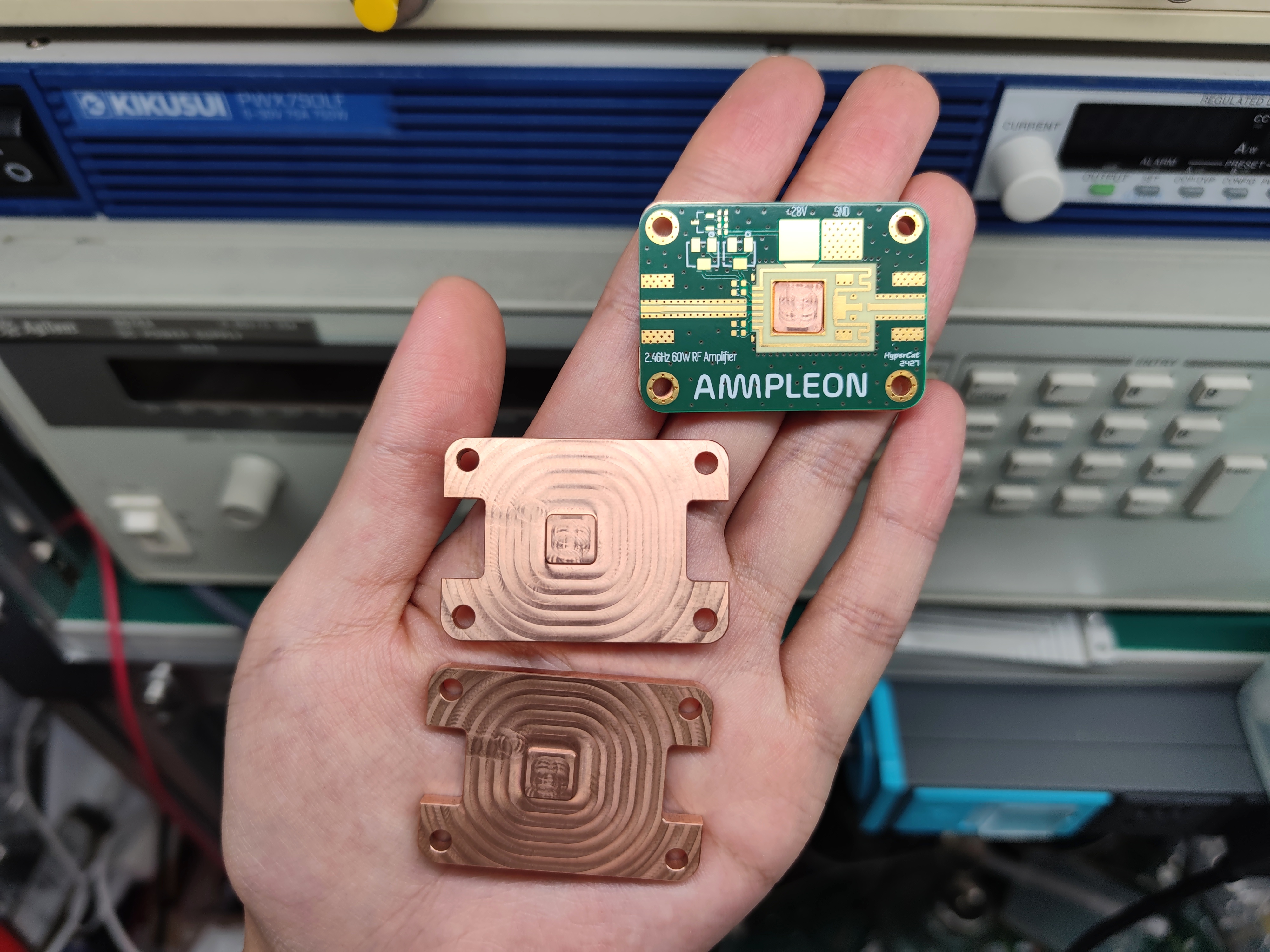
2.4G 60W RF power amplifier
This 2.4GHz 60W RF power amplifier is commonly used in the industry for signal jammers, drone countermeasures, wireless image transmission, and other applications. The transistor model is BLM10D2327-60ABG.
Disclaimer:
This open-source project is intended for professionals in the RF industry or users with basic RF knowledge, for academic exchange.
This project is shared free of charge for academic exchange purposes only and is prohibited from being used for illegal or commercial purposes. Users without RF background and related RF instruments are not advised to replicate this project, as unprofessional operation may lead to potential dangers. Replicating, or using, or referencing this project in any other form, constitutes acceptance of this disclaimer and full understanding of its contents. All dangers and consequences arising from replicating, or using, or referencing this project in any other form are the sole responsibility of the user and are not the responsibility of the project author.
I. Origin:
I accidentally discovered a neat-looking power amplifier tube, model BLM10D2327-60ABG. Its small size, high power, and attractive appearance appealed to me. So I made a board to play around with it.
II. Chip Information:
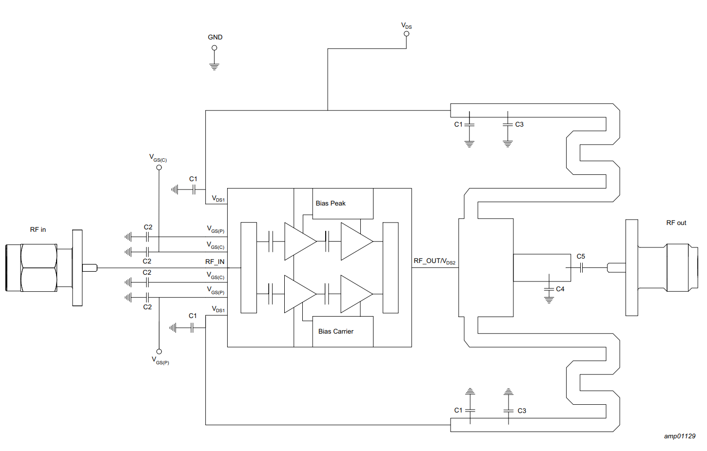
1. Chip Block Diagram:
As shown in the block diagram, this is a commonly used power amplifier structure in base station power amplifiers. However, this transistor integrates matching, power splitting, combining, and other components, making it more convenient to use and smaller in size. This is advantageous in applications where size is critical, such as PRRUs (Pre-Release Units). The specific principles will not be elaborated upon here; this open-source project is intended for users with some basic RF knowledge.

According to the manual,
this power amplifier transistor operates in the 2.4GHz band. With good heat dissipation, the gain is approximately 28dB, and it can output a maximum CW pulse power of +48dBm, which is 63W. The efficiency is approximately 40% or higher when the output power is +40dBm.

III. Electrical Design:
1. Power Supply Voltage Selection:
According to the manual, a 28V DC power supply is recommended.
2. BIAS Circuit Design:
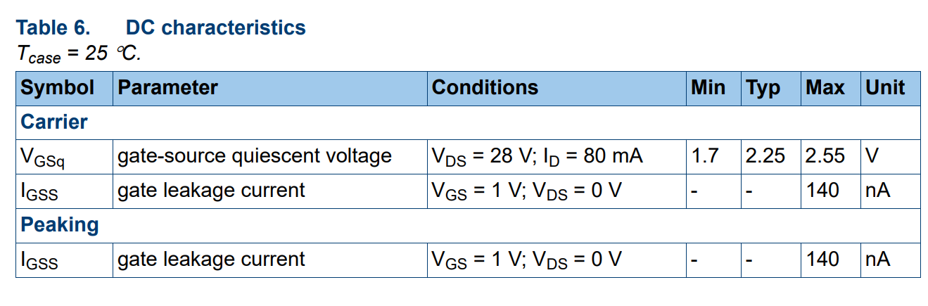
First, refer to the manual to determine the VGS voltage range.
As shown in the table below, the allowable voltage range of VGS is -6~+9V.

Continuing to read the manual, it can be seen that the required bias voltage during normal operation is approximately within 3V.
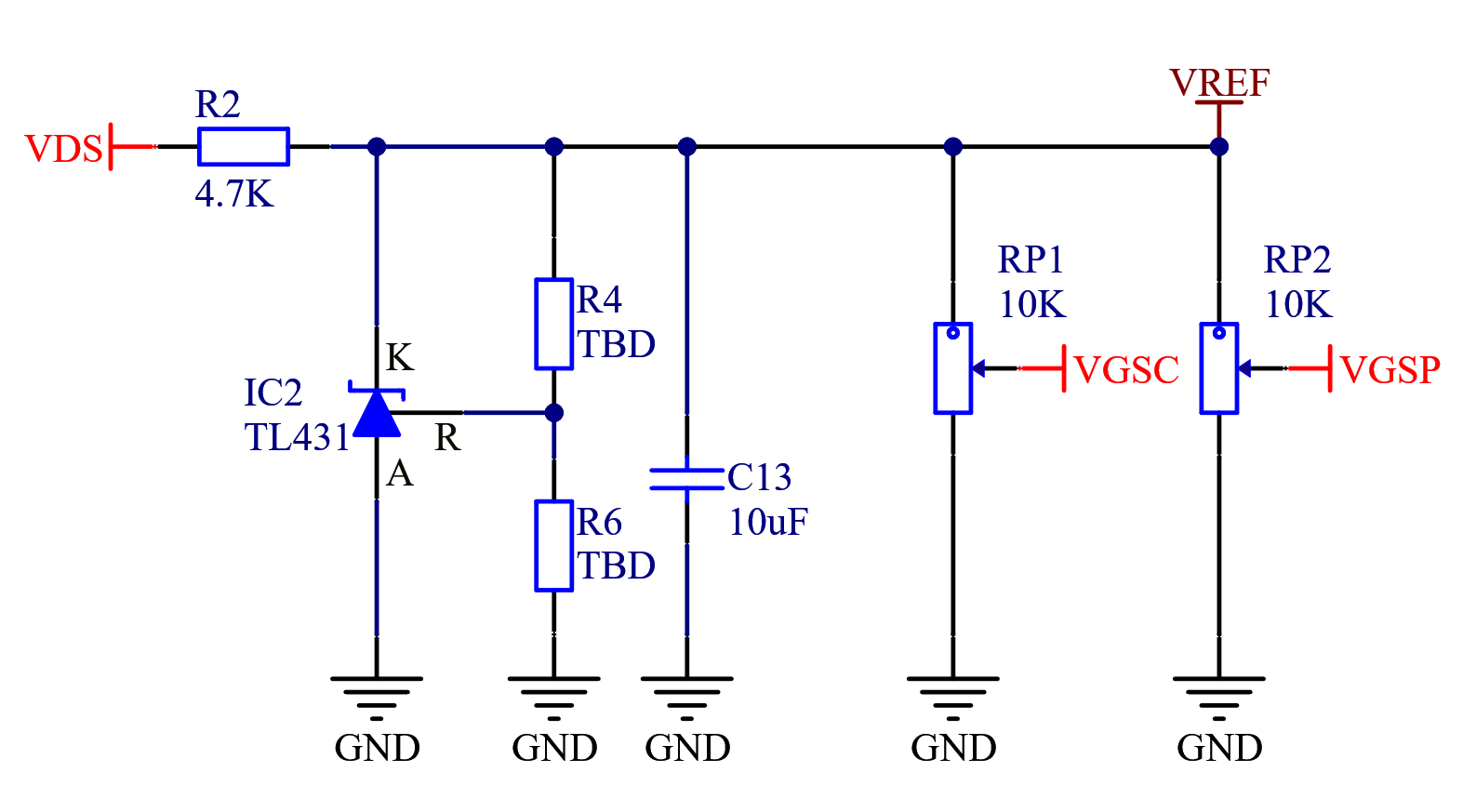
Since the bias has very low current requirements, we use the TL431 voltage reference chip to regulate the 28V power input to a stable VERF.
1.1 TL431 Principle:

The TL431 can be considered equivalent to a Zener diode. Its basic connection method is shown in the figure below. Figure a can be used as a 2.5V reference source, and Figure b can be used as an adjustable reference source. The relationship between resistors R2 and R3 and the output voltage is UO = 2.5(1+R2/R3)VO.

The VREF obtained from the TL431 is used as a voltage divider to provide biases for Peak and Carr respectively.
IV. Matching Circuit Design:
Since this transistor lacks an ADS model and S-Parameters, only the load impedance is provided in the datasheet. The datasheet also provides a matching reference design for the required frequency band, so we simply use the reference design to verify its functionality.
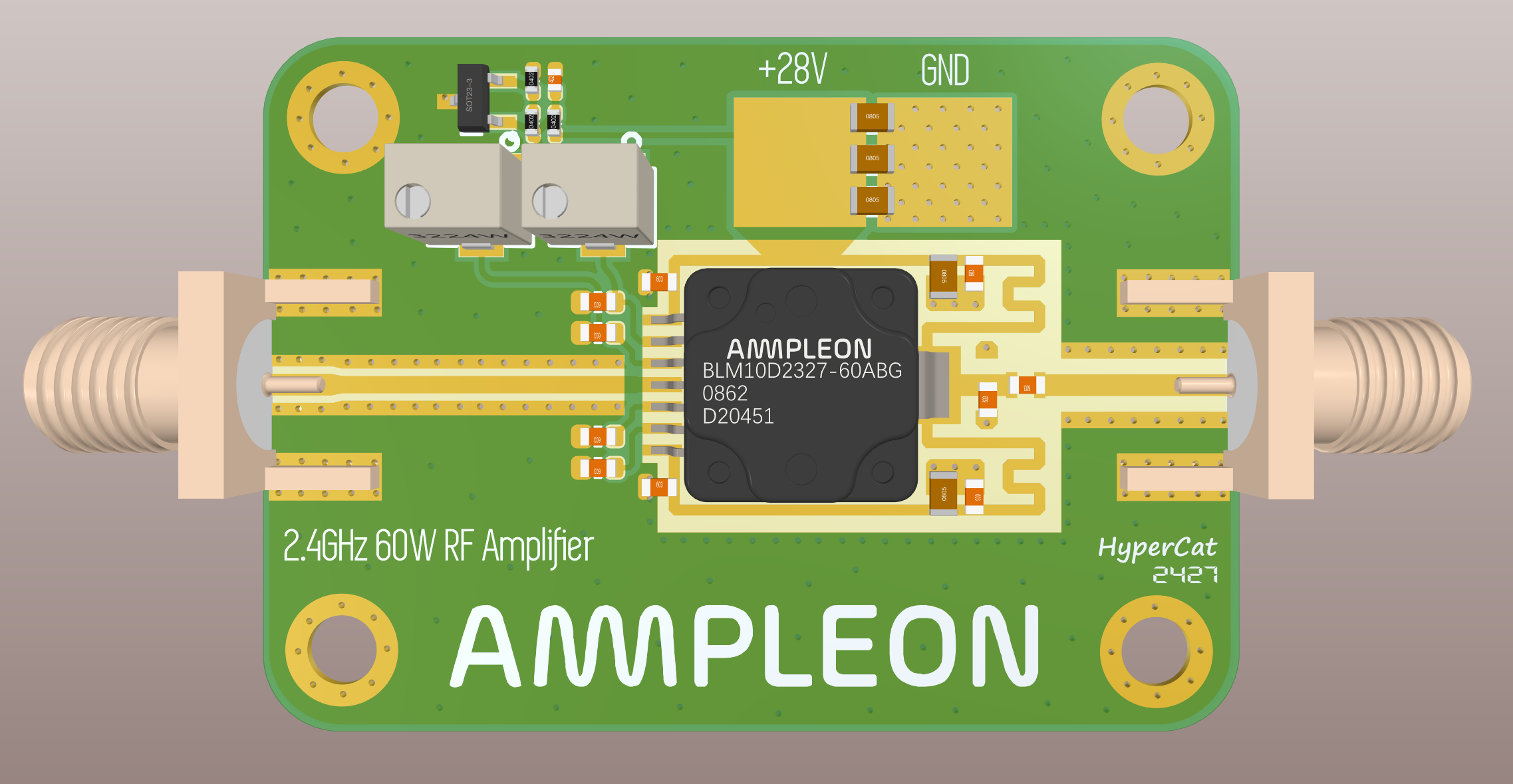
V. PCB Design: See LCSC EDA .
This image is a 3D rendering.
VI. Heat Dissipation Design:
Due to the significant heat generated by the RF power amplifier, a good heat dissipation design is necessary; otherwise, it will overheat and burn out. This transistor has no mounting lugs, so it needs to be soldered to a heatsink, which also serves as grounding and heat dissipation material.
The manual also recommends soldering directly to the heatsink material.

Therefore, we need to design a heatsink base for soldering, so the material must be copper, not aluminum.
Seven: Manufacturing:
Due to the high frequency and power, the microstrip matching is designed based on the dielectric constant of the 4350. Therefore, the PCB must be made of Rogers RO4350B 0.508 board material, not FR4, otherwise there will be mismatch, severe overheating, power reduction, and in severe cases, chip burnout.
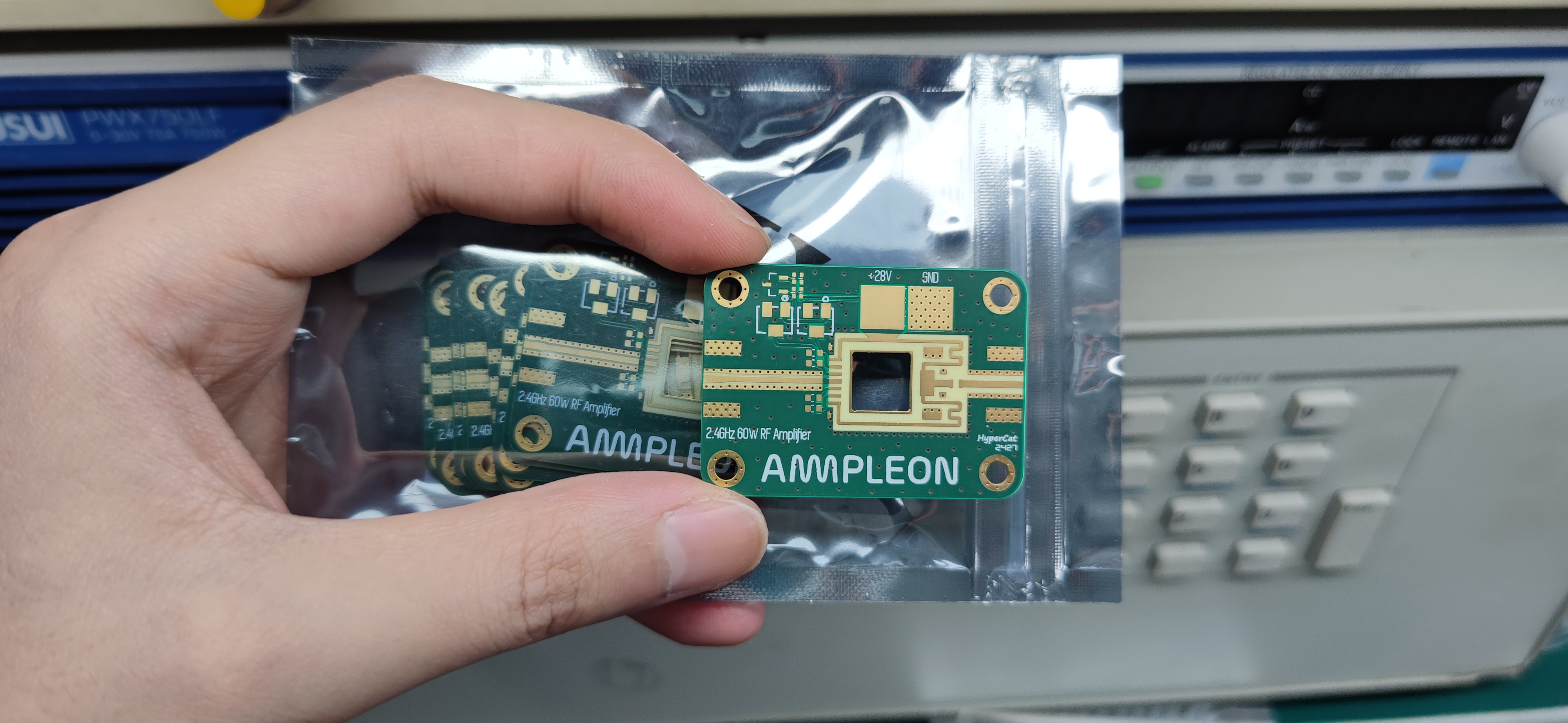
The heatsink must be made of copper, machined by CNC. Copper has good heat dissipation and is also necessary for soldering.
Eight: Soldering and Assembly:
1. Finished product image after soldering:


 京公网安备 11010802033920号

 SLE66CX80PEM5


