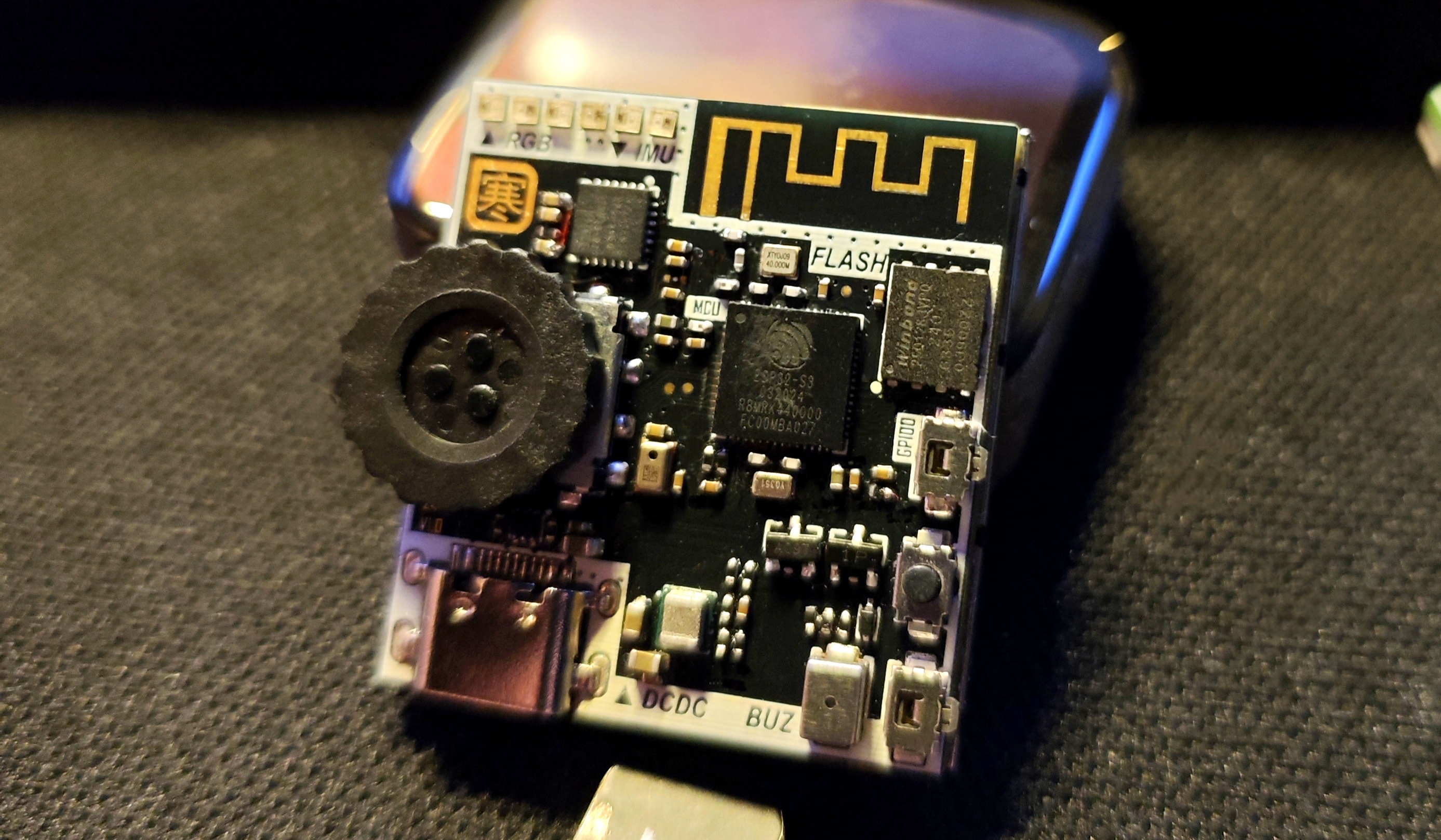
This is a development board that uses the ESP32S3 (optional ESP32S3R2 and ESP32S3R8, with a floating PSRAM pin on the circuit) as the main control chip. I used it for learning and developing example programs. It
has an exquisite appearance and a clear structure. The schematic diagram includes supplementary explanations of the circuit
. Below are some suggestions for replicating it:
First, some component connections —>
Screen address (click)
Roller encoder address (click)
Buzzer address (click)
Microphone address (click)
RGB LEDs can be found on the LCSC website, model WS2812E-1313.
Note! If you only have a soldering iron and no heating element, you should reconsider.
This board cannot be soldered without a heating element. A recommended configuration is a soldering iron + heating element + hot air gun.
Remember to use enough flux! Remember to use enough flux! Remember to use enough flux!
Due to the board's design, all sides are slightly narrower than the screen. Therefore, please carefully align the components before assembling the screen. Applying tape will make it difficult to move
the board. The screen is a 12-pin soldering type; please do not purchase the wrong one. If you happen to have a 1.54-inch screen, you can check the pinout. Incorrect pinouts will make it difficult to remove
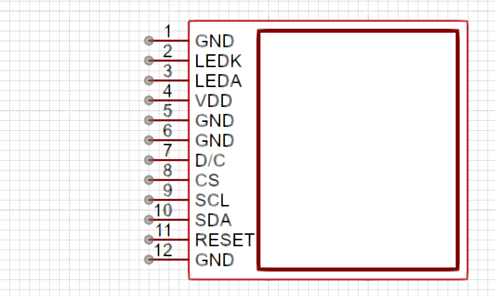
the screen without damage after soldering. The screen uses a MOSFET as the backlight adjustment switch, connected to GPIO14, which can be configured in the program to adjust the backlight brightness.
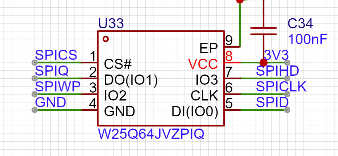
The FLASH chip used on the board has a smaller package than usual; it is a WSON8-6X5. You can choose between W25Q128JVPIQ and W25Q256JWPIQ for replacement.
The microphone is a discontinued silicon microphone; I bought some unused ones when making small toys, so I'm using them as is.
The I2C pull-up resistor can be replaced with a 10K resistor, as long as it's not less than the specified value.
Regarding the power chip, the TI large inductor is used (it's really eye-catching). Its compact size belies its impressive output capability (3A current).
The formula for calculating the output voltage is as follows:
VOUT = VFB X (1 + R1 / R2) = 0.8VX (1 + R1 / R2).
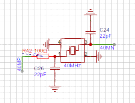
Due to the close proximity of the crystal oscillator to the antenna in the board design, I chose to place a resistor to weaken the crystal oscillator's driving capability, according to Espressif's official documentation. This resistor cannot be omitted or replaced with 0Ω, as shown in the diagram below.
Regarding the onboard buttons, besides the programmable scroll encoder,
GPIO46 and GPIO0 can be pulled down to enable the programming mode. EN enables the mode, and pulling it down stops it from working.
In other words, press and hold SW1 and SW2, then press SW3 to enter programming mode.

Normally, GPIO46 and GPIO0 can be configured separately.
(


A
little note: When soldering, please solder resistors, capacitors, inductors, crystal oscillators, chips, transistors, MOSFETs, buzzers, and other heat-resistant components first.) After cleaning the flux, solder the RGB LEDs, scroll encoder, button switches, and microphone, which are easily damaged. This prevents repeated desoldering and heating from damaging the components. After checking that everything is correct and cleaning off the flux, power on and test all sensors to ensure they are working properly before soldering the screen.
Happy retouching!
I used Thonny to test the onboard sensors and screen, and obtained some libraries from GitHub. The relevant code will be uploaded to the attachment.
(Wanhan, August 4, 2024)


 京公网安备 11010802033920号

 10118884-502006LF


