This project is a modification of the LM2596S_ADJ Adjustable Power Module - LCSC Open Source Hardware Platform (oshwhub.com).
I. Chip Introduction:
The LM2596S is a step-down switching regulator integrated circuit widely used in various power conversion scenarios. It can provide up to 3A of output current and has excellent line and load regulation performance. The LM2596S includes internal compensation and a fixed 150kHz oscillator, reducing the number of external components and simplifying the design. This chip is available in fixed output voltage versions (3.3V, 5V, 12V) and adjustable output voltage versions, with an adjustable output voltage range from 1.2V to 37V.
II. Chip Parameters
: - Output Type: Provides fixed or adjustable voltage output.
- Voltage - Input (Max): 40V.
- Voltage - Output (Adjustable Range): 1.2V to 37V.
- Voltage - Feedback (Typical): 1.23V.
- Current - Output (Max): 3A.
- Current - Static (typical): 80μA (standby mode).
- Efficiency (typical): Over 80% at 12V input and 3A load.
- Package/Case: TO-220 (T) and TO-263 (S).
- Mounting Type: Through-hole or surface mount.
- Operating Temperature: -40°C to 125°C.
III. Application Areas
The LM2596S is suitable for a variety of applications, including but not limited to:
- Battery-powered devices.
- Home appliances.
- Grid infrastructure.
- Power conversion for electronic products.
IV. Chip Physical Structure
The LM2596S chip has 5 pins, including input (VIN), output (OUTPUT), ground (GND), feedback, and enable/disable (ON/OFF). The chip integrates an oscillator, regulator, comparator, and protection circuitry.
V. Package Size
The LM2596S is available in two different package types:
- TO-220 (T): Suitable for applications requiring higher power output and a larger heat dissipation area.
- TO-263(S): Surface mount package, suitable for space-constrained or automated assembly environments.
VI. Relevant Parameters
- Maximum Input Voltage: 45V.
- Feedback Voltage Range: -0.3V to 25V.
- Static Output Voltage: -1V.
- Storage Temperature: -65°C to 150°C.
- Operating Temperature: -40°C to 125°C.
- Efficiency: Varies with different loads and input voltages, but is typically between 70% and 90%.
VII. Typical Application Circuits
The LM2596S can be configured with a fixed or adjustable output voltage. For adjustable output, the desired output voltage is set using an external resistor divider, calculated as
Vout = Vref * (1 + R6/R3), where Vref is the internal reference voltage of 1.23V.
Note: Here, LED1 is closer to the Vout interface, and LED2 is closer to the input interface.
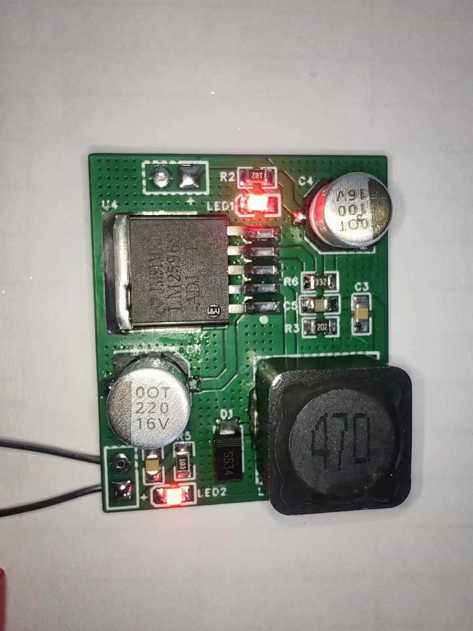
This is a repair example of a Newland device 3.3 power supply failure.
The 100uf capacitor is optional; it can be a tantalum capacitor (it seems to be more efficient) or an electrolytic capacitor.
If anyone needs a fixed voltage version or how to configure the resistors, please leave a comment.
Hand soldering is not recommended for this project due to the high component density. Unless you are an expert, disregard this.


 京公网安备 11010802033920号

 MAX7645BCPP


