This project is a motor drive module based on the L9110S chip, featuring four functions: direct drive for forward/reverse/stop/brake.
① The L9110S_FOUR has four input control terminals, which can control four output terminals to directly drive the motor's forward and reverse rotation.
② Reverse connection protection.
③ Three motor interfaces suitable for various motors.
④ The chip integrates over-temperature protection and undervoltage lockout protection functions.
: Supports a maximum operating voltage of 12.0V, continuous current of 1.2A, and peak current of 2.0A.
successfully tested with an 8.4V input voltage, and the L9100S chip did not overheat.
2. PWM Drives Four Motors.zip
Video Link:
Bilibili Video -- [Kamen Rider GAVV] Universal Open Source GAVV Battery~
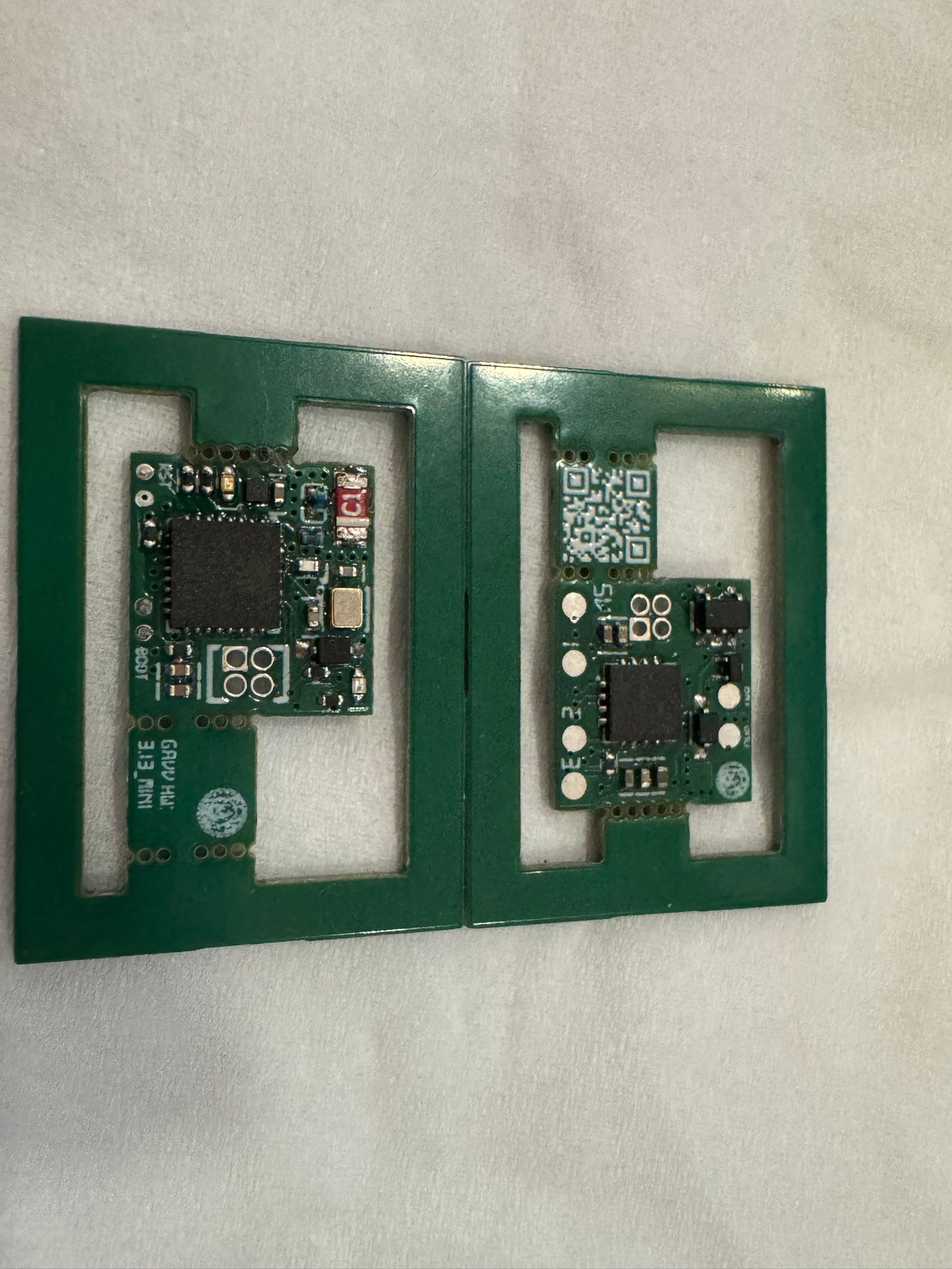
Project Introduction
This project is a universal battery design based on MCP4661+ESP32C3! Very low cost~
QQ Group: 827536876
Project Functionality
Universal! Open Source! It's actually very simple; it uses a digital potentiometer to change the value of the identification resistor in real time, thus achieving universal functionality~ A 256-bit 100k resistor is just enough to achieve a recognition range from 5.6k to 62k.
Project Parameters
MCP4661 Digital Potentiometer
ESP32C3 as the main controller
TP4056 for battery charging
Software Code
GAVV_Custom_Gochizo
Please
like, comment, and subscribe! The project is complete and currently supports WebBLE network configuration. APP/mini-program development is underway!
Update Log
V3.13 Replaced the chip with MCP4661-104E, optimized some layouts for greater accuracy.
V2.11 moved the wake-up function to the charging location, ensuring it's always awake while charging. Extremely power-efficient during normal use, perfect!
V2.10 fixed instability caused by excessive capacitor removal, optimized circuit routing, and added new contacts at the charging point.
V2.6 removed the magnet wake-up function and added GPIO10 to G01 to switch between insertion and removal states (no need to remove the capacitor).
V2.4 added GPIO4 as the wake-up source connected to G02, so it wakes up simply by inserting, eliminating the need for a magnet. ~
Finished product image

PDF_[Kamen Rider Gavv] All-Purpose Collection.zip
Altium_[Kamen Rider Gavv] All-Purpose Collection.zip
PADS_[Kamen Rider Gavv] All-Purpose Collection.zip
BOM_[Kamen Rider Gavv] Omnipotent Collection.xlsx
91721
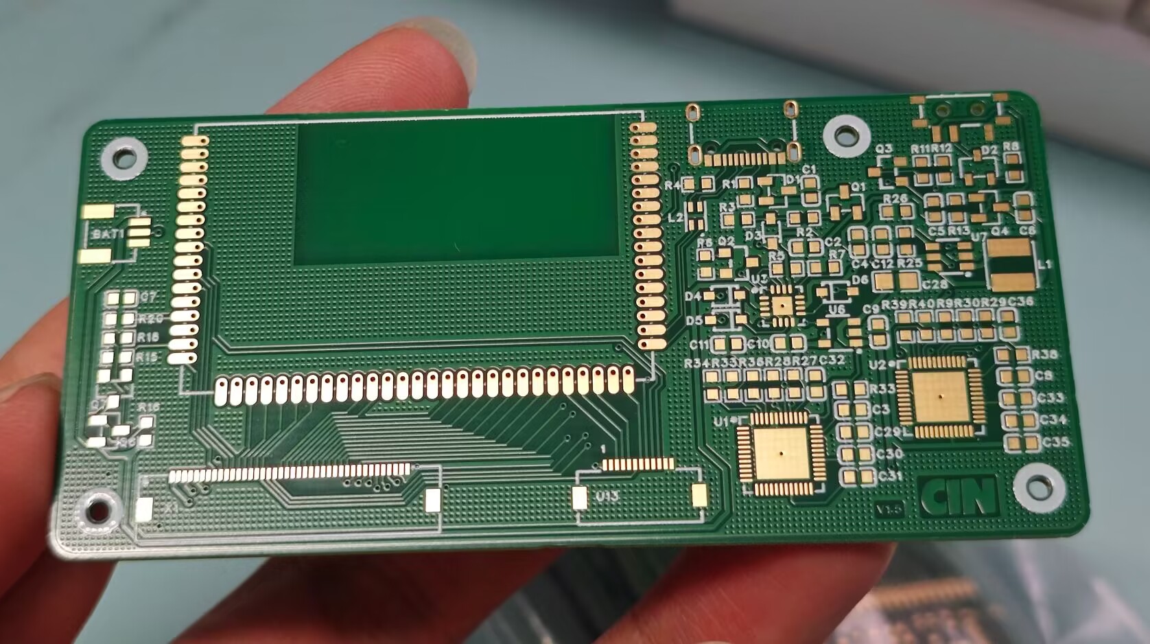
Logitech G913 schematic and modifications (verified)
The project has been verified, and the v1.5 prototype can recognize it. Some individual chips were not found or were replaced with better alternatives. The BOM (Bill of Materials) can be exported from the PCB itself.
A new project group chat has been created. Materials will be uploaded and group purchases will be organized in the group if needed: 907854382.
Updated August 29, 2024: Re-layout v1.5 and prototyped, placing the LED controller next to the main controller. The v1.5 prototype has passed recognition testing. To avoid wasting resources, it is strongly recommended to make a prototype and test it yourself first.
Introduction: This project is a schematic diagram drawn by myself based on reverse engineering of the G913, including a main controller verification board and modified reference routines. I hope everyone can make a keyboard that meets their expectations.
Estimated cost: 80 RMB per board with the main controller, 120 RMB per receiver, and multiple sets of various components can be purchased for under 100 RMB.
Tips: Main controller startup is conditional, peripheral circuit enable conditions are complex, and successful LED controller communication is required for recognition in ghub. Pay attention to the I2C pull-up resistor position and communication lines when drawing the PCB. Verify the current-limiting resistors for the LEDs yourself. The uploaded project is a backup and has some minor issues (such as component packaging). Please feel free to leave feedback in the comments section. I will gradually upload other resources later.
File tree description: The modified example is a three-piece set: main control board + axis board + encoder board, with a special 98-key layout. A CNC shell model is available; please request it from the group. The key layout of the modified example is still being verified; implementation will take a few days. The main control daughterboard is used to adapt the original main control board to a smaller keyboard space, but the packaging is very difficult to solder.
PDF_Logitech G913 Schematic & Modified (Verified).zip
Altium Logitech G913 schematic & modified (verified).zip
PADS Logitech G913 schematic & modified (verified).zip
BOM_Logitech G913 Schematic & Modified (Verified).xlsx
91722
JLink-V9-Mini-V1.0
The mini version of JLink V9 is only 1.5 x 4 cm. It features a JTAG interface with 12MB SWD and 15MB JTAG bandwidth.
The schematics and firmware are from the internet. I only modified some component packages and redrawn the PCB.
Replacing the JLinkARM.dll file in the JLink installation location will not trigger piracy warnings, and you can use JLink-related tools such as jflash and ozone.
bootloader.bin
JLinkARM.dll
Instructions.txt
PDF_JLink-V9-Mini-V1.0.zip
Altium_JLink-V9-Mini-V1.0.zip
PADS_JLink-V9-Mini-V1.0.zip
BOM_JLink-V9-Mini-V1.0.xlsx
91723
GD32F407VET6 Expansion Board
Skystar GD32F407VET6 Expansion Board
I participated in the design call for an expansion board. Previously, I'd been learning about LEDs and digital tubes, so I took this opportunity to design a communication board, including Ethernet, RS232, and RS485.

I chose the W5200 Ethernet chip, which, according to the datasheet, has the same pinout as the W5100 and W5500. The main reason was its lower price on Taobao. I'll just post a picture for reference; I
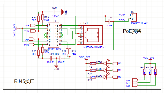
already had the interfaces and transformers on hand, so I didn't use an integrated one. Since it's a 100M chip, pin 4578 isn't needed. I also brought out the PoE power supply.

The RS232 and RS485 circuits were built according to the datasheet. Components were from the Taobao store 16-15; thanks to LCSC!

Soldering complete. I used a board from the Open Source Plaza, modified to black and white silkscreen, and tested it after soldering; it works perfectly.
LCSC has abundant resources, and the LCSC development board provides learning materials, which will keep me entertained for a long time.
PDF_GD32F407VET6 Expansion Board.zip
Altium_GD32F407VET6 Expansion Board.zip
PADS_GD32F407VET6 Expansion Board.zip
BOM_GD32F407VET6 Expansion Board.xlsx
91724
electronic
 Principle Analysis (Hardware Description):
  The project was
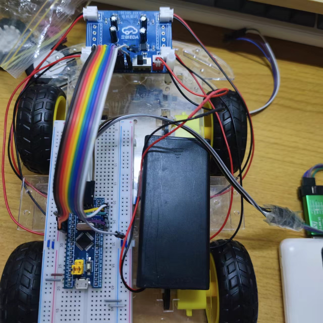


 京公网安备 11010802033920号

 KGEA-BFCAM-B-0500-J


