Project Introduction
This project is based on the ESP32-S3 development board and features homework registration and FC game playback.
1. Homework registration is my own idea. The UI is designed using the LVGL library.
In the digital age, mobile phones have become an indispensable tool for children to complete their homework. Prolonged mobile phone use not only affects eyesight but can also distract children. Therefore, I wanted to create a homework registration toy to help children manage their homework efficiently and cultivate good study habits.
2. The FC game is the open-source Retro-Go. To deeply recreate the gaming experience of childhood, a separate design was adopted for the screen and development board.
3. Learning and gaming use two sets of code. With sufficient resources, two SP32-S3 development boards and two SD cards can be used to recreate the fun of inserting cartridges.
Project Functionality
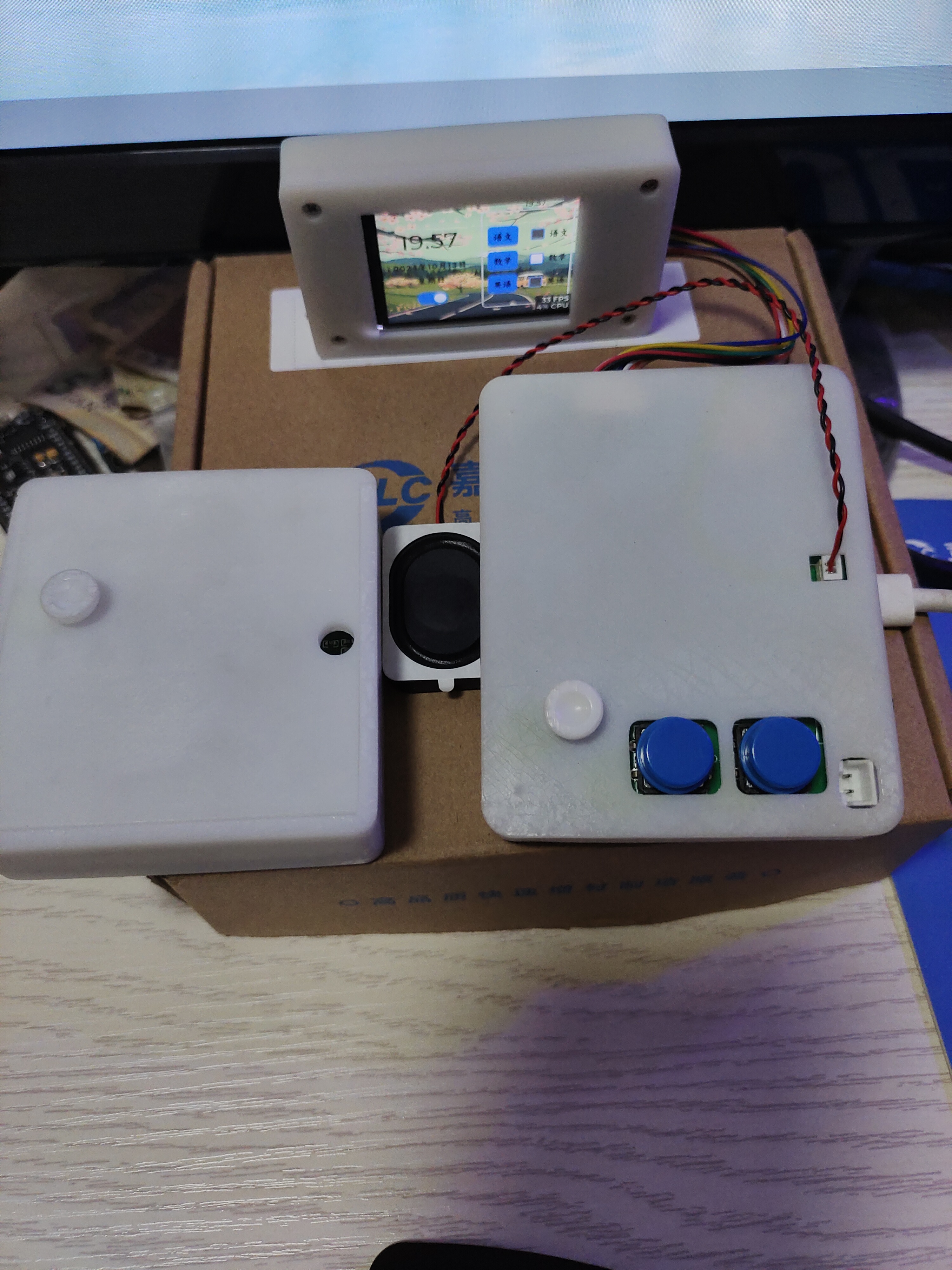
This design is based on the ESP32-S3 development board; it has multiple buttons for FC games, an ST7789 screen to display homework completion status and FC game visuals, an SD card to store homework registration prompts, English listening and reading recordings, and FC game playback, and a speaker amplifier for sound playback.
When using homework registration, it can be controlled simply by using the dial buttons on the right side.
When parents are nearby, the ESP32 has offline voice wake-up and command recognition functions. You can use [https://oshwhub.com/lililip/bluetooth-speaker-network-radio-] which has a microphone. Voice wake-up and commands are sent via ESP-NOW to the control interface. Point the command
directly at the microphone, for example: "Hi, Lexin" + "Chinese," "Hi, Lexin" + "Open screen," etc.
Project parameters
: This design uses the ESP32-S3 development board as the main controller;
this design uses an ST7789 240*320 LCD display to show whether homework is completed and the screen content of FC games;
this design uses an SD card for storage;
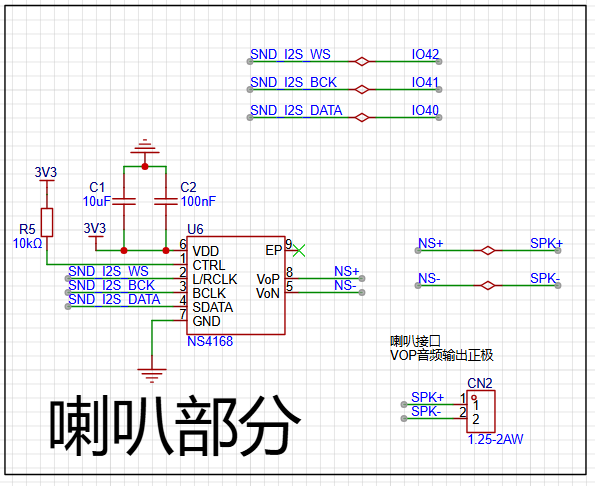
this design uses an NS4168 as the amplifier for sound playback;
the homework completion interface displays whether Chinese, Math, and English are completed. The Chinese interface has a sub-interface image displaying the Chinese homework requirements. The English interface has a sub-interface for playing listening and reading recordings; the
homework registration program, power-on timer, and pressing KEY A can enter the interface to view the homework.
The FC game interface is based on games I played as a child.
The hardware explanation is as follows:
Due to the development board design, the circuit is very simple.
The SD card circuit
uses SPI communication, with pull-up resistors on each line.

The power amplifier circuit
uses I2S communication.
A pull-up resistor on the CTRL pin keeps the sound output always on.
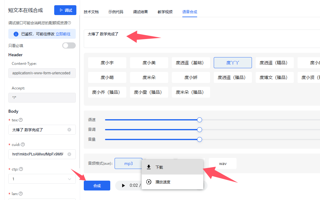
The prompt sound is based on C3 Practical Guide's Baidu Text-to-Speech tutorial:
https://lceda001.feishu.cn/wiki/Xqx3wH8wMi3BrrkmeTXcgLL7nQk.
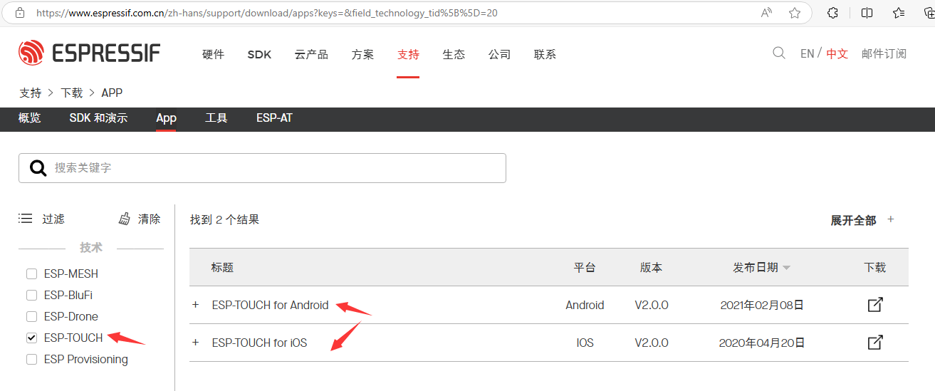
The debugging interface is shown in the image. The mobile network is configured using the ESP-TOUCH software
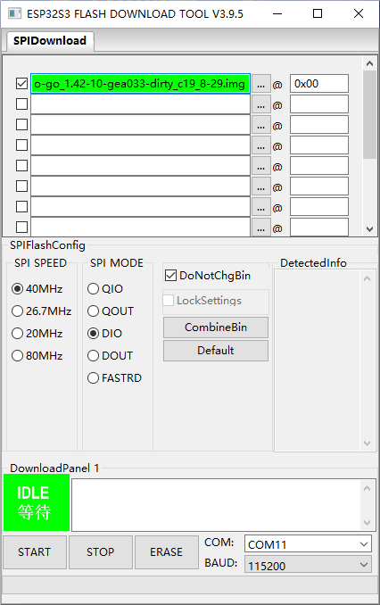
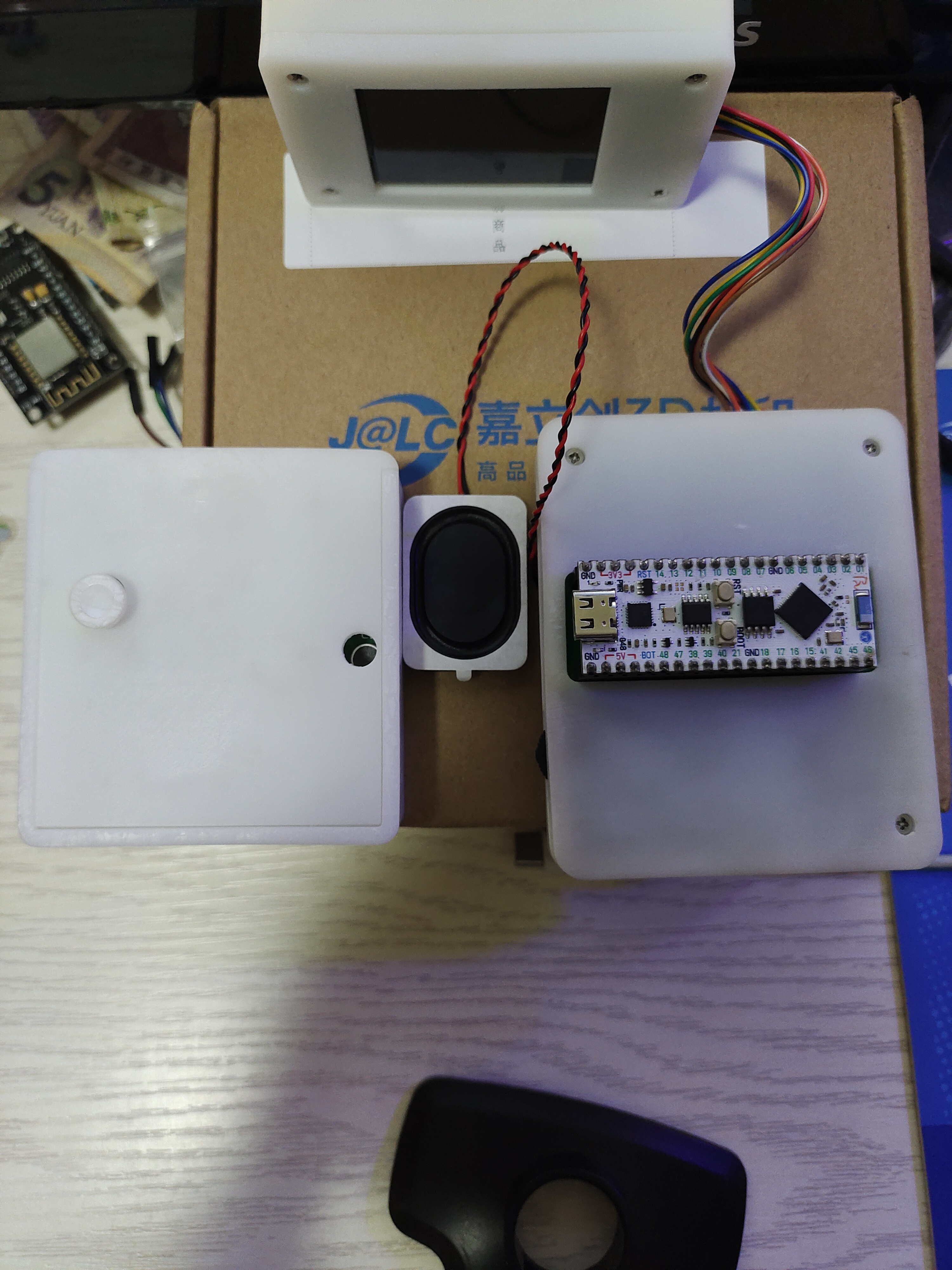
downloaded from the Espressif website . The assignment registration is in the project attachment source code. The FC game is an uploaded .bin file . If you have any questions, please leave a comment. Notes: This section can be used to highlight key points or common mistakes during design and development. Example: The development board's power strip should be plugged into the back; check the silkscreen on the board. Pay attention to the board's orientation to avoid unpredictable problems. The development board can be powered via USB or battery. The battery interface is connected to the 5V port on the development board; a 3.7V lithium battery may need to be boosted to 5V. To recreate the gaming experience of childhood, the screen and main controller are connected separately using a ribbon cable. Images of the completed product can be included here: Figure 1: Game Interface; Figure 2: Assignment Log; Figure 3: Back of the Development Board.

h264_video_20241013_202222.mp4
video_20241013_201210.mp4
video_20241013_185925.mp4
lceda.zip
retro-go_1.42-10-gea033-dirty_c19_8-29.img
PDF_Homework Registration and FC Game Console Combined.zip
Altium_Homework Registration and FC Game Console Combination.zip
PADS_Homework Registration and FC Game Console Combination.zip
BOM_Homework Registration and FC Game Console Combined.xlsx
91730
STM32H750X STM32H743X baseboard
This is an expansion board for the STM32H750/H743 core board, featuring an onboard STLink v2.1, MPU6050, FDCAN, RS485, camera, SD card, 1.14-inch RGB LCD, and common communication interfaces.
This is a self-made STM32H750/H743 core board expansion baseboard. It includes an onboard STLink v2.1, MPU6050, FDCAN, RS485, camera, SD card, and a 1.14-inch RGB LCD. It features two serial ports, one I2C interface, and one SPI interface.
A Bilibili unboxing video of the core board is available here: https://www.bilibili.com/video/BV14TsaeRE8B/?share_source=copy_web&vd_source=5442d7b4a0763d92ecc90a20c86d3ed1.
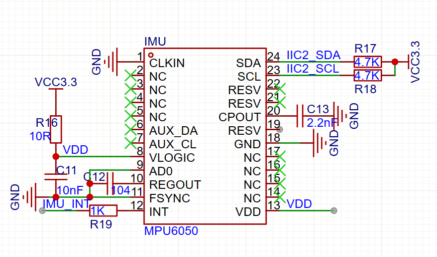
The values of the two capacitors for the gyroscope have been modified (C11: 10nF, C13: 2.2nF). Those who have previously built such boards should take note of this to ensure proper operation.
STLinkV2.J28.M18.bin
Physical demonstration.mp4
PDF_STM32H750X STM32H743X Baseboard.zip
Altium_STM32H750X STM32H743X baseboard.zip
PADS_STM32H750X STM32H743X baseboard.zip
BOM_STM32H750X STM32H743X Baseboard.xlsx
91731
Sky Star Extension Board
Compatible with GD32F407VET6, STM32F407VGT6, and HC32F4A0PITB series SkyStar development boards
The system aims to support peripheral interfaces for
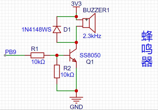
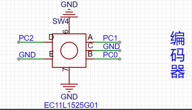
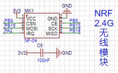
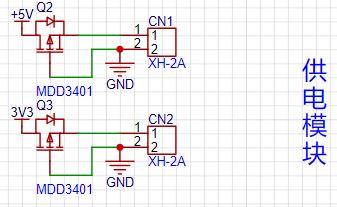
GD32F407VET6, STM32F407VGT6, and HC32F4A0PITB , including: tri-color LEDs, 2.4G wireless modules, motor drive modules, buzzers, rotary encoders, temperature and humidity sensors, OLED display modules, and LCD display modules . Expansion pins include GPIO and power supply interfaces. The interface modules include: 1. Buzzer Module: This module adds a freewheeling diode (to prevent damage from voltage spikes, as buzzers are inductive components) and a transistor. The PB9 pin controls the transistor's on/off state, thus controlling the buzzer's switch. 2. 0.96-inch OLED Module: This 0.96-inch OLED module is compatible with most I2C interfaces on the market and includes a 10K pull-up resistor for stable communication. It uses PB6 and PB7 for communication. 3. 1.8-inch LCD Module : This 1.8-inch LCD module connects directly according to the interface definitions, using GPIOs PA5, PA7, PB0, PB1, PB10, and PD6. 4. Digital Tube Module: The digital tube module uses an AIP650 shift register and a 4-digit digital tube. A filter capacitor has been added to the chip's power supply port. GPIOs used are PD0 and PD1. 5. Encoder Module: The encoder module is relatively simple, directly connected to the microcontroller's GPIOs, with software debouncing. GPIOs used are PC0, PC1, and PC2. 6. Ultrasonic Module: The ultrasonic module's power supply section has added filter capacitors to stabilize the power input. GPIOs used are PC10 and PC11. 7. Temperature and Humidity Module: The temperature and humidity module uses a Sensirion STH41 chip, communicating with the microcontroller via I2C. A 10K pull-up resistor has been added for stable communication. The PCB layout incorporates a cutout design, placing the chip on the bottom to reduce the impact of PCB temperature and dust. GPIOs used are PB8 and PB9. 8. 2.4G Wireless Module: The wireless module has added filter capacitors. GPIOs used are PA2, PB8, PB9, PB13, PB14, and PB15. 9. Motor Module: The motor module features output filtering and a reserved motor interface, with a maximum output current of 1.8A and a peak current of 2.5A. GPIOs used are PD14 and PD15. 10. Power Supply Section: For safety, a PMOS transistor is added for reverse polarity protection, and it should be used only to power peripherals. Software Section: The software development primarily uses KEIL and the STM32 CUBE IDE. Example programs can be found on the LCSC official website: https://wiki.lckfb.com/zh-hans/tkx/. Most of the example code is directly usable, with consistent GPIO pin interfaces, making it very suitable for beginners. [GD32F407VET6 Version] Baidu Cloud link for beginner's manual download: https://pan.baidu.com/s/1CFs39v8Ev3JDlkErcUDglw?pwd=ffff Extraction code: ffff Module porting code download: https://pan.baidu.com/s/1fkPoWqAyFUtIIVbM1sNK2Q?pwd=cbhf Extraction code: cbhf [HC32F4A0PITB Version] Baidu Cloud link for beginner's manual download: https://pan.baidu.com/s/14M6ovaOl71TVgmRD00rIjA?pwd=ef82 Extraction code: ef82 Module porting code download: https://pan.baidu.com/s/1ZeGzmg2KqSkeb-llBn-lw?pwd=g7es Extraction code: g7es [STM32F407VxT6 Version] Baidu Cloud Link : [Standard Library] Introductory Manual Download: https://pan.baidu.com/s/1kDTqSKuQRyudF34XczzIFg?pwd=dc1q Extraction Code: dc1q [Standard Library] Module Porting Code Download: https://pan.baidu.com/s/17XoMY-u3VMqCJ7sFAdpNlQ?pwd=tlub Extraction Code: tlub Note: Due to size limitations, the 1602LCD and optocoupler modules have been removed. The ultrasonic module and the 0.96-inch OLED module cannot be installed simultaneously. The 0.96-inch OLED module is installed using a 4-pin 2.54mm header for easy installation and removal. Power output is used only for output purposes, and reverse polarity protection has been added.


PDF_SkyStar Extension Board.zip
Altium_SkyStarExtensionPad.zip
PADS_SkyStar Expansion Board.zip
BOM_SkyStar Expansion Board.xlsx
91733
MP1584 step-down module - 5V output (verified)
A step-down module based on MP1584, with an input of 6-18V and an output of 5V.
For circuit design, you can refer to this article
: 5V Output Circuit Design - CSDN Blog.
The output voltage is changed by altering the value of resistor R1; the specific formula is mentioned in the article. R1 is not shown in the picture because the wrong resistor was purchased. Soldering a 10k resistor resulted in a stable output of 0.99V, conforming to the formula
. Changing the resistor to 210kΩ resulted in a stable 5V output, which has been verified.
PDF_MP1584 Step-Down Module - 5V Output (Verified).zip
Altium MP1584 step-down module - 5V output (verified).zip
PADS_MP1584 step-down module - 5V output (verified).zip
BOM_MP1584 Step-Down Module - Output 5V (Verified).xlsx
91734
ESP32 Weather Calendar
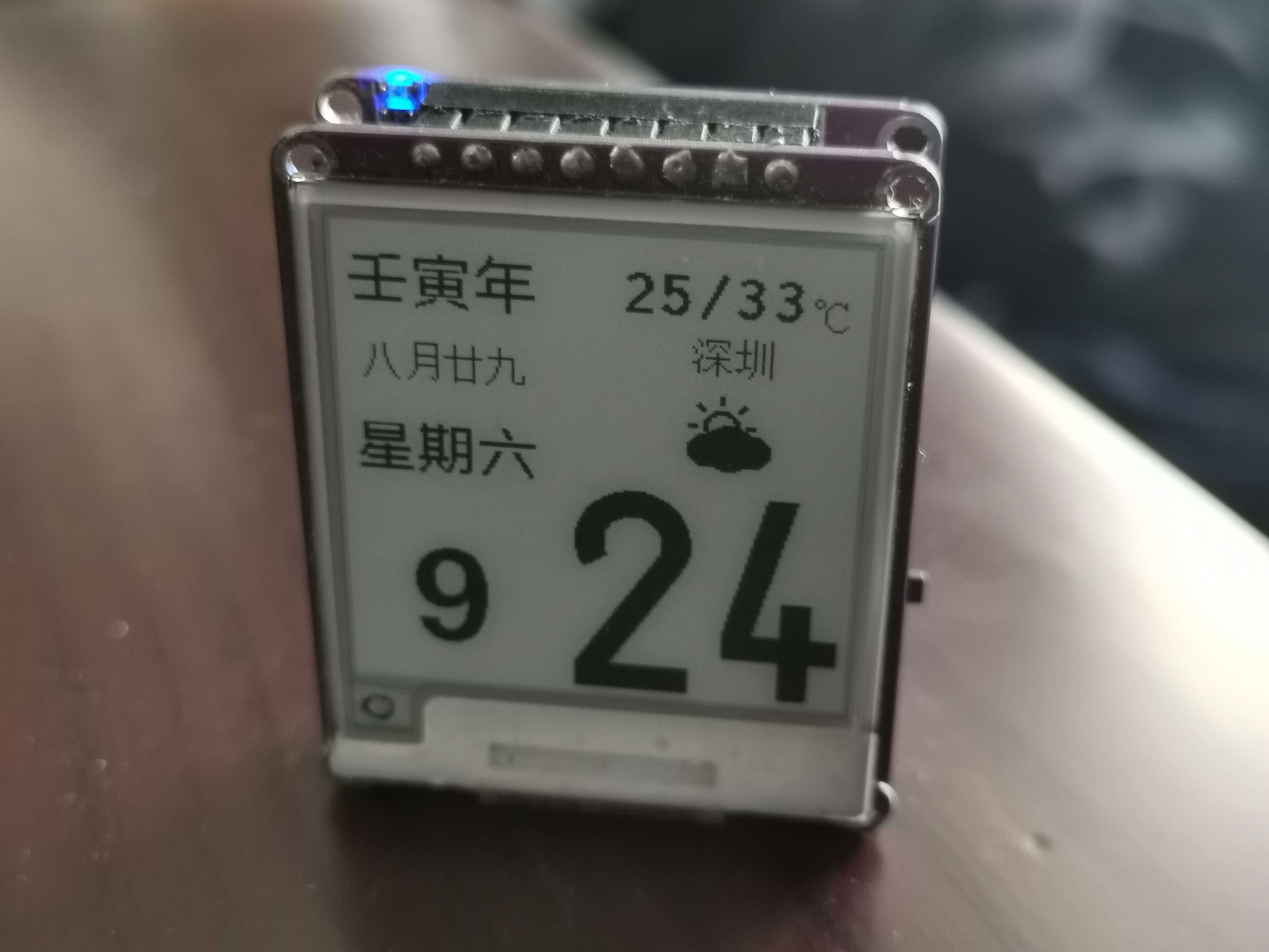
Calendar and Weather E-ink Display Based on ESP32
Key Features:
This project uses ESP32 to access Xinzhi Weather (https://api.seniverse.com/v3/weather/daily.json) and NTP date, updating approximately once daily around midnight. The data is displayed on an e-ink screen.
Battery consumption only occurs when accessing WiFi and refreshing the e-ink screen. However, ESP32 operation mode consumes more power; a 200mAh battery lasts less than a month
with daily wake-up for automatic refresh.
Project Deployment Tutorial
: Arduino is used; I used VS Code + Platform.io for easier compilation.
You can also apply for a Xinzhi Weather API account; the daily free attempts are sufficient.
Install the ESP32 driver
, compile, and flash
the demo images.
PDF_esp32 Weather Calendar.zip
Altium_esp32 Weather Calendar.zip
PADS_esp32 Weather Calendar.zip
BOM_esp32 Weather Calendar.xlsx
91735
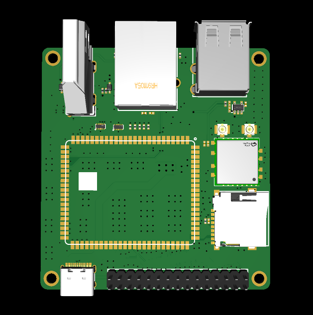
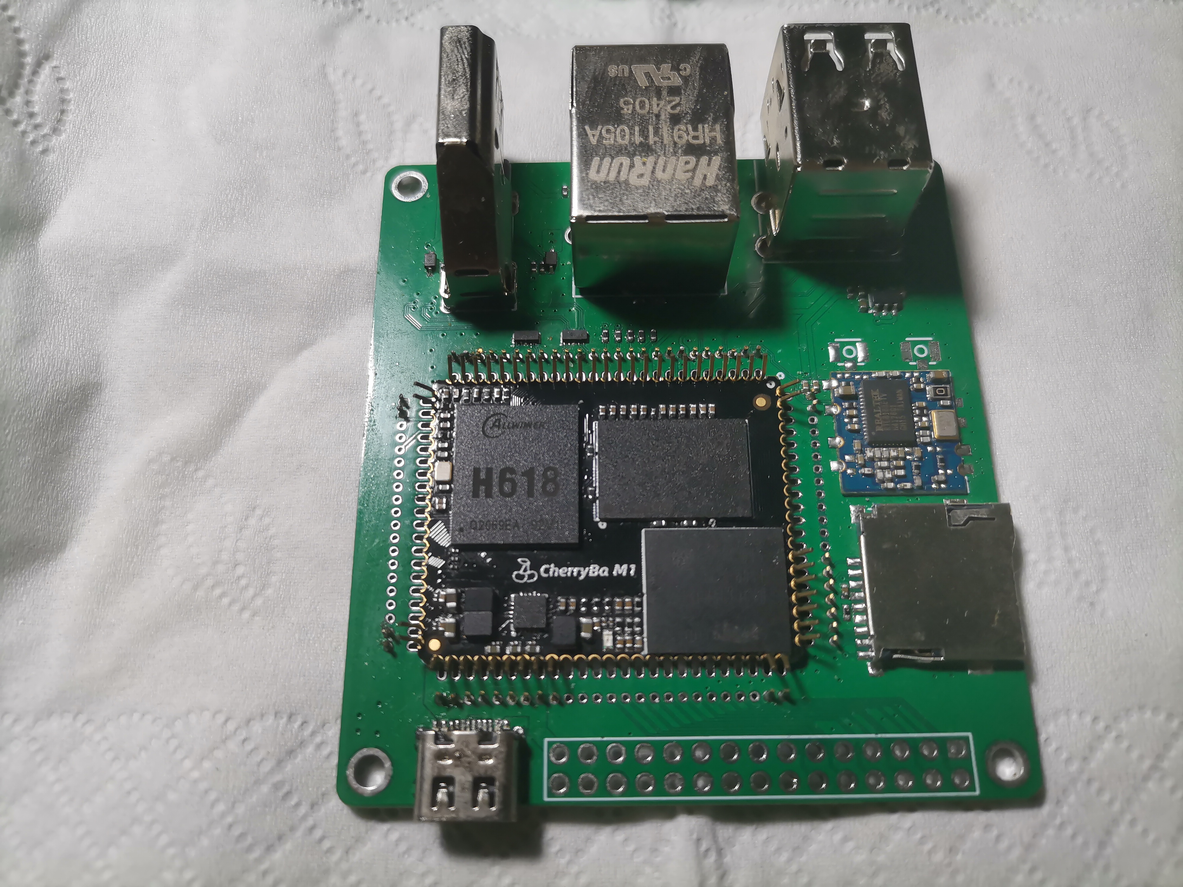
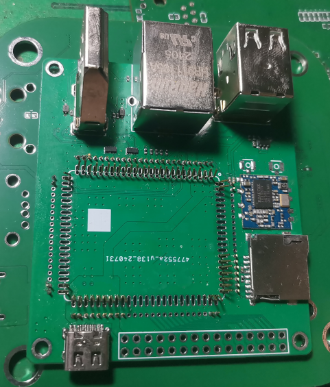
CherryM1 H618 core base plate
The base plate of the Cherry BaM1 core board
Onboard Resources
: CPU: 4 * A53;
Memory: LPDDR4 1G/2G;
Network: USB WIFI module;
Display: HDMI 4K@30
interfaces :
1. TF card
; 2. USB; 3.
Type-C; 1
; 4. HDMI; 1
; 5. Ethernet; System
: Ubuntu 22.04
Deban11
Deban12
Armbian;
Performance:
CPU frequency 1.5GHz;
Notes:
The automatically generated BOM list below is incorrect, please do not use
it. Select JLCPCB when ordering >>> 2-layer board
, 1.6mm thickness.
Core version link;
Image &
source code provided in QQ group files. Other
communication QQ groups: 169300702.
(Image)
PDF_CherryM1 H618 Core Baseboard.zip
Altium_CherryM1 H618 core baseplate.zip
PADS_CherryM1 H618 Core Baseboard.zip
91736
Adjustable portable power supply with charging function
Based on the LM317 adjustable power supply, it has two built-in adjustable power outputs and two LM1117 3V3 outputs.
1. The battery input is boosted to power the LM1117 and LM35. My boost module, adjusted to a 15V adjustable power supply, can output up to approximately 13V.
2. A master switch is included for easy shutdown when not in use, reducing power consumption on the boost module. The master switch must be turned on when charging the charging module is connected.
3. When attaching the battery to the back, a piece of cardboard can be added to prevent component pins from scratching the battery.
WeChat image_20241012151922.jpg
WeChat image_20241012153013.jpg
WeChat image_20241012153021.jpg
WeChat image_20241012153027.jpg
a70d6ab999f2917733bf7cb3b75bdba0.mp4
PDF_Adjustable Mobile Power Supply with Charging.zip
Altium_Adjustable Mobile Power Supply with Rechargeable Charging.zip
PADS_Adjustable Mobile Power Supply with Rechargeable Charging.zip
BOM_Adjustable portable power supply with charging.xlsx
91737
Commonly used non-isolated low-power step-down power supplies
A typical low-power step-down power supply with a common voltage range of 12V~35V input, stepping down to 12V-8V-5V-3.3V-1.8V-1.2V output.
Actual testing shows normal operation. Input
voltage:
12-35V DC;
Output voltage:
12V DC,
8V DC
, 5V DC
, 3V3 DC,
1.8V DC,
1.2V DC.
Output limit current:
12V---5A
, 8V-----5A
, 5V-----2.4A ,
3.3V--3A
, 1.8----500mA
, 1.2----1A.
Note:
The onboard 12V--8V is a switching power supply: the output current capability can be calculated based on the power rating. However, the 5V-3.3V-1.8V-1.2V are linear regulators, and their output current capability is related to the input current capability and cannot be calculated based on the power rating.
PCB soldering requires attention to the direct connection of the GND section to the copper-plated area; therefore, a high-power soldering iron is recommended for easier soldering.
Numerous GND interfaces are placed on the board for convenient use.
This board is a simple step-down module; the input voltage must be greater than a specific output voltage to achieve an accurate output voltage.

PDF_Common Non-Isolated Low-Power Step-Down Power Supplies.zip
Altium_Common Non-Isolated Low-Power Step-Down Power Supplies.zip
PADS_Common Non-Isolated Low-Power Step-Down Power Supplies.zip
BOM_Common Non-Isolated Small Power Step-Down Power Supplies.xlsx
91738
electronic


 京公网安备 11010802033920号

 D125012440.5%P0


