Project Overview:
The TI XDS110 is essentially an open design applicable to many scenarios, such as Keil MDK, IAR Embedded Studio, OpenOCD, TI CCS Studio, etc. This project is compatible with the J-Link shell and features CMSIS-DAP and TI's proprietary JTAG download and debugging capabilities. It has been tested with devices such as the TI C2000 TMS320F28035, MSP432P401YT, and STM32F401CCU6, and theoretically supports all ARM Cortex processors and most TI DSP devices, as well as mmWave SoCs or Wireless MCUs.
The XDS110 integrates a virtual serial port with a speed of at least 115200 MHz, a significant improvement over the J-Link v9. It provides a relatively high-speed serial port for convenient debugging without requiring a dedicated USB-UART chip. This project is based on the LP-EXP432E401Y schematic with slight modifications, and the level conversion circuit is based on the ACTG schematic with slight modifications. It supports downloading and simulating 1.8V, 3.3V, and 5V MCUs.
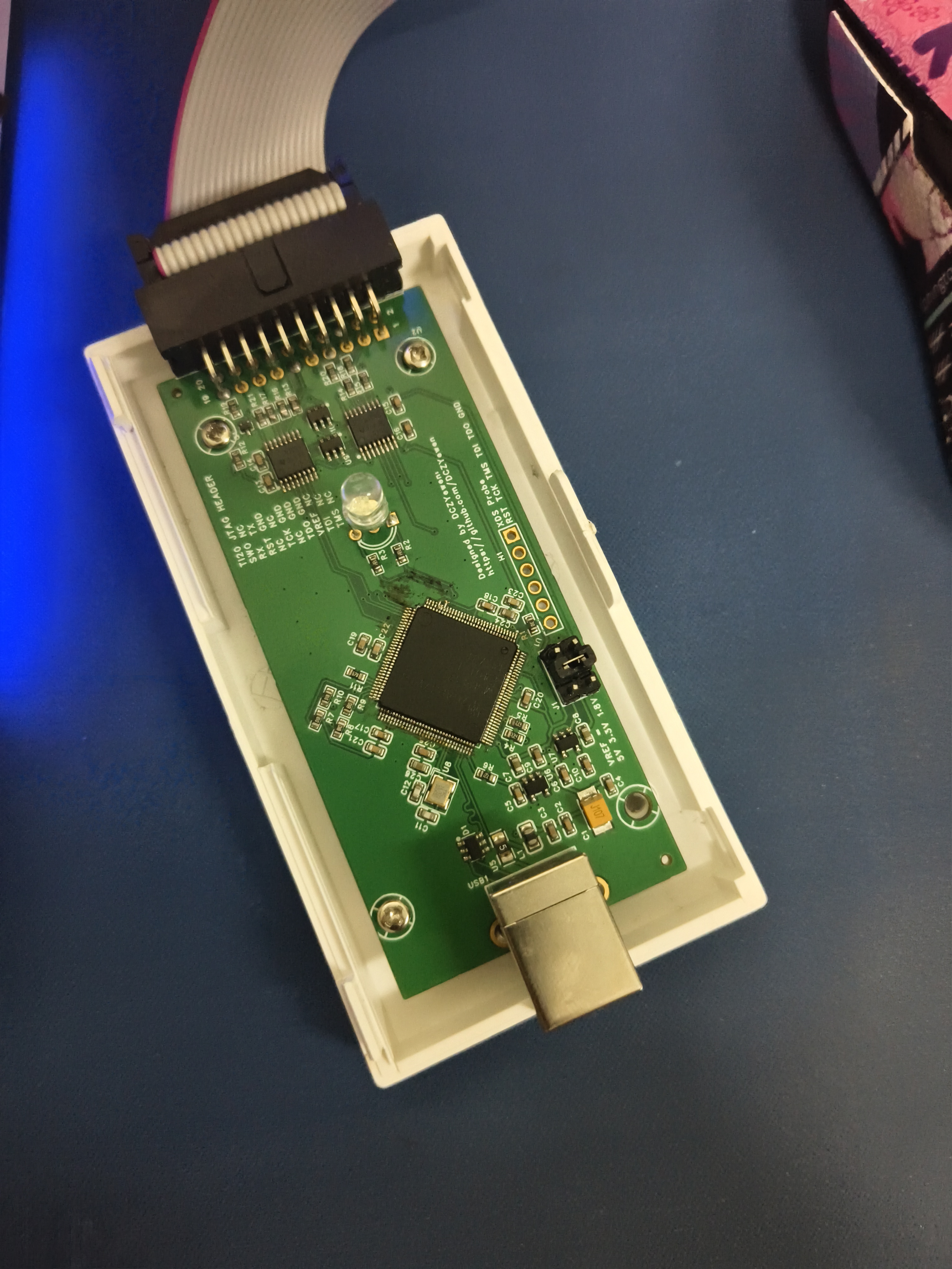
This project has a standard Ti-20 JTAG interface, allowing direct connection to development boards compatible with the Ti-20 JTAG interface. An adapter board allows downloading and simulating (most DSP devices) for development boards with the Ti-14 JTAG interface. It also supports Cortex Debug and ARM Serial Wire Debug interfaces. The adapter board is open-source at another link. The
original JTAG connector was a mirror image; this has been fixed in the new version.
The adapter board is open-source
, but the KiCAD project cannot be open-sourced on OSHWHub; please visit GitHub.
Important Notes:
All resistors and capacitors in this project use 0603 packages for easy hand soldering. It is strongly recommended to use a laser-cut stencil and a heated platform for soldering. The LQPF-128 package is extremely difficult to solder, often resulting in missing solder or bridging. SMT is preferred if possible. All components are on the front for easy soldering on the heated platform.
If SMT is used, pay attention to the orientation of the components.
The main chip can be an MSP432E401YT, TM4C1294NCPD, or TM4C129ENCPD; these three components are identical under the XDS110 firmware. According to GPT and other sources, the TM4C129E is an enhanced version of the TM4C1294, and the MSP432E401Y is a low-power version of the TM4C series.
After successful XDS110 soldering, a bootloader needs to be flashed. The required firmware and bootloader are integrated into TI CCS Studio and CCS Thiea, so ensure you have a working CMSIS-DAP or J-Link before prototyping and replicating.
After flashing the bootloader, the XDS110 operates in DFU mode. The firmware needs to be flashed using the xds110dfu tool. After inputting the necessary information, it will function normally.
The new firmware for the XDS110 supports Drag and Drop flash, but in practice, this is not very useful; standard mode is recommended. Drag and Drop flash only supports MSP432, Tiva, and C2000 series devices.
The board has a JTAG interface for the XDS110, and an SWD interface can also be used. If using SWD, connect SWDIO to the TMS and SWCLK to the TCK. It can be flashed using MCU Prog or J-Flash.
Different target levels can be selected using jumpers on the board.
Firmware flashing steps:
First, use other hardware such as J-Link, DAPLink, XDS110, etc., and flash the bootloader using MCU Prog, Jflash, Uniflash, or OpenOCD. Open
the command prompt and navigate to the XDS110 firmware folder in CCS
... `uscifxds110$ ./xdsdfu.exe -f ./firmware-xxxx.bin -r`
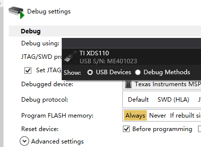
Testing shows that not changing the XDS110 serial number may cause problems in certain specific places. When connecting a normally functioning XDS110
... `uscifxds110$ ./xdsdfu.exe -m`
Enter DFU mode
... `uscifxds110$ ./xdsdfu.exe -s ME401023 -r`
This serial number is the serial number of the LP-EXP432E401 LaunchPad's onboard XDS110 probe.
You can use `xdsdfu -c ?` The command displays the
modes supported by XDS110, which can be switched arbitrarily. Contact information
: https://github.com/DCZYewen
contact@stu.hebust.edu.cn
Screenshot of successful operation.
The successfully created XDS110 probe can work in OpenOCD with CMSIS-DAP configuration or using XDS110 configuration.
Successful debugging of STM32F103C6 is shown

in the finished product image.
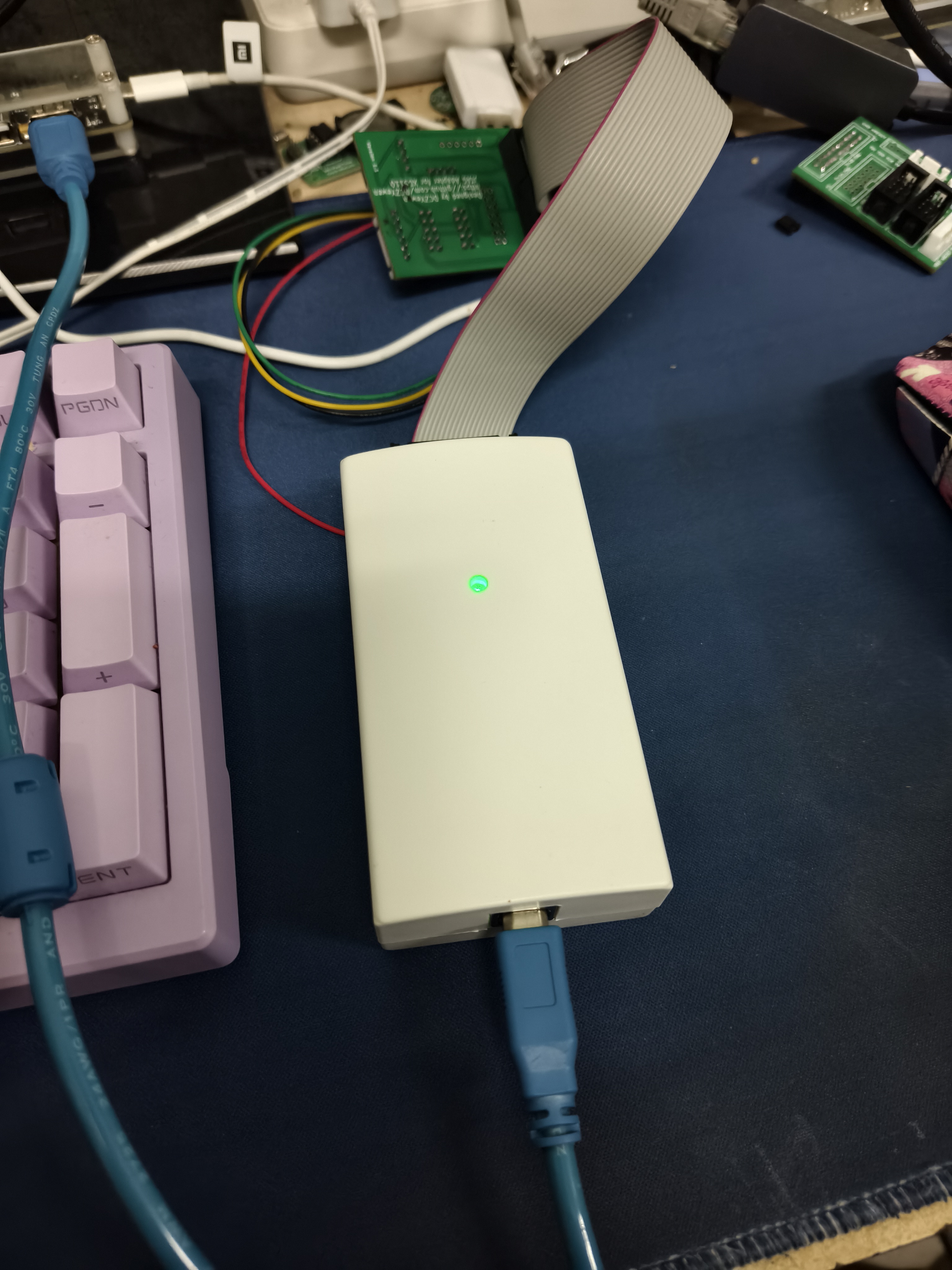
It is recommended to use this inexpensive debugging probe to flash the bootloader.
XDS110-Debug-Probe_Gerberfiles.zip
PDF_XDS110 test probe.zip
Altium_XDS110 test probe.zip
PADS_XDS110 test probe.zip
BOM_XDS110 test probe.xlsx
91822
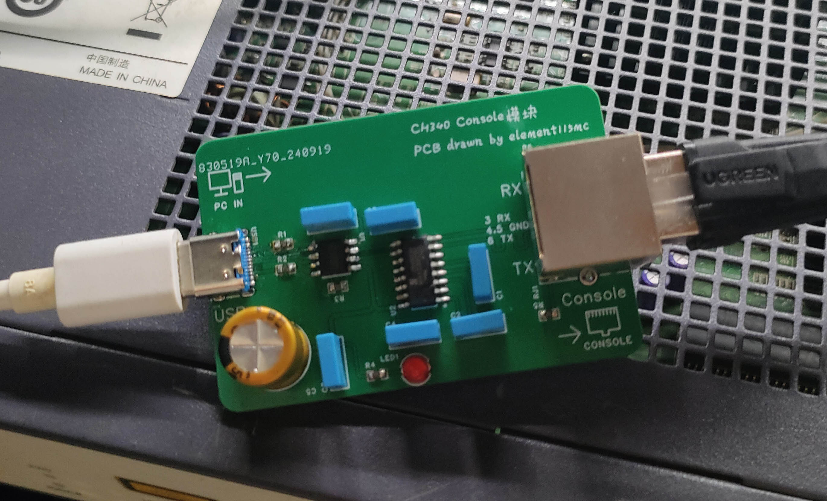
CH340 Console Module
Simple, practical, stable, driver-uninterrupted, and low-cost switch console port communication module
This console communication module uses the ultra-stable CH340 solution and is compatible with Win11 systems.
The reason for making this: I bought a switch with a console port to play around with, but found that the console cables on the market were not very reliable. Those using the PL2303 solution couldn't install drivers on Win11, and on Win7, the drivers would drop frequently, requiring a restart to fix. Console cables using the FT232 solution were extremely expensive. After researching the working principle and communication levels of the console port, I decided to build my own better and cheaper console communication module.
Features: Made using the CH340N USB-to-TTL chip and MAX232, it has a simple structure, stable operation, and low cost. Only one A-to-C data cable and one network cable are needed to enable communication between the computer and the switch's console port.
Usage:
1. Prepare an A-to- C data cable... C. Data cable and a cable of length
2. Since the Console port uses RS232 level communication, which involves high voltage, hot-plugging the RS232 level port while it is powered on can easily damage the port circuit. It is recommended to first connect the module's network port to the switch's Console port using a network cable, and then use A to... 3. Connect the computer's USB-A port to the Type-C port on the module using the C data cable. 4.
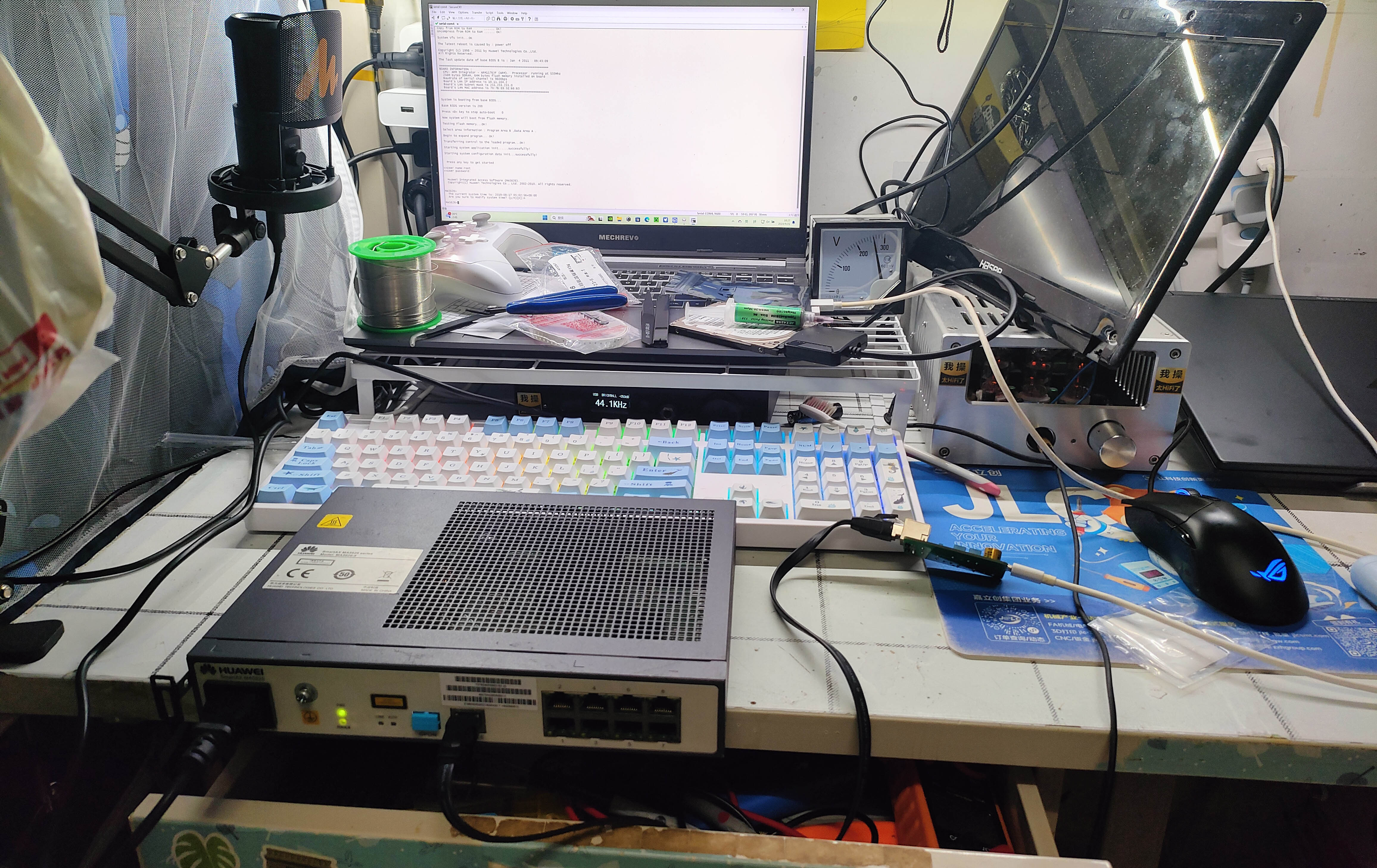
After configuring SecureCRT and other software to suit the switch's communication parameters, you can communicate with the switch's Console port.
5. After completing communication, it is recommended to disconnect the USB connection first, then disconnect the physical connection of the Console port (for the same reason as point 2).
Friendly Links
: Demonstration (Bilibili): One-click link to Bilibili
CH340 Official exe Driver: One-click link to official download
Important Reminders
: 1. Because the Console port uses RS232 level communication, the voltage is relatively high (-9V, +9V). Hot-plugging RS232 level ports while powered on can easily damage the port circuitry. Recommended connection order: Console port → USB; Disconnection order: USB → Console port.
2. The indicator lights on the network port are only used to show the active status of the RX and TX communication lines and are unrelated to the network connection status.
3. Do not mistake this device for a USB wired network card and attempt to establish a network connection using it (if you can't even distinguish this, there's no need to be a network engineer or have a need for this module).
4. This device's network port is only allowed to connect to the switch's Console port (this is the purpose of this module's design). It is forbidden to connect this device's network port to any other device's regular network port or PoE port. [Image of the device
itself connected to the switch; image of communication results with the switch (9600 baud rate)]

PDF_CH340 Console module.zip
Altium_CH340 Console module.zip
PADS_CH340 Console module.zip
BOM_CH340 Console module.xlsx
91823
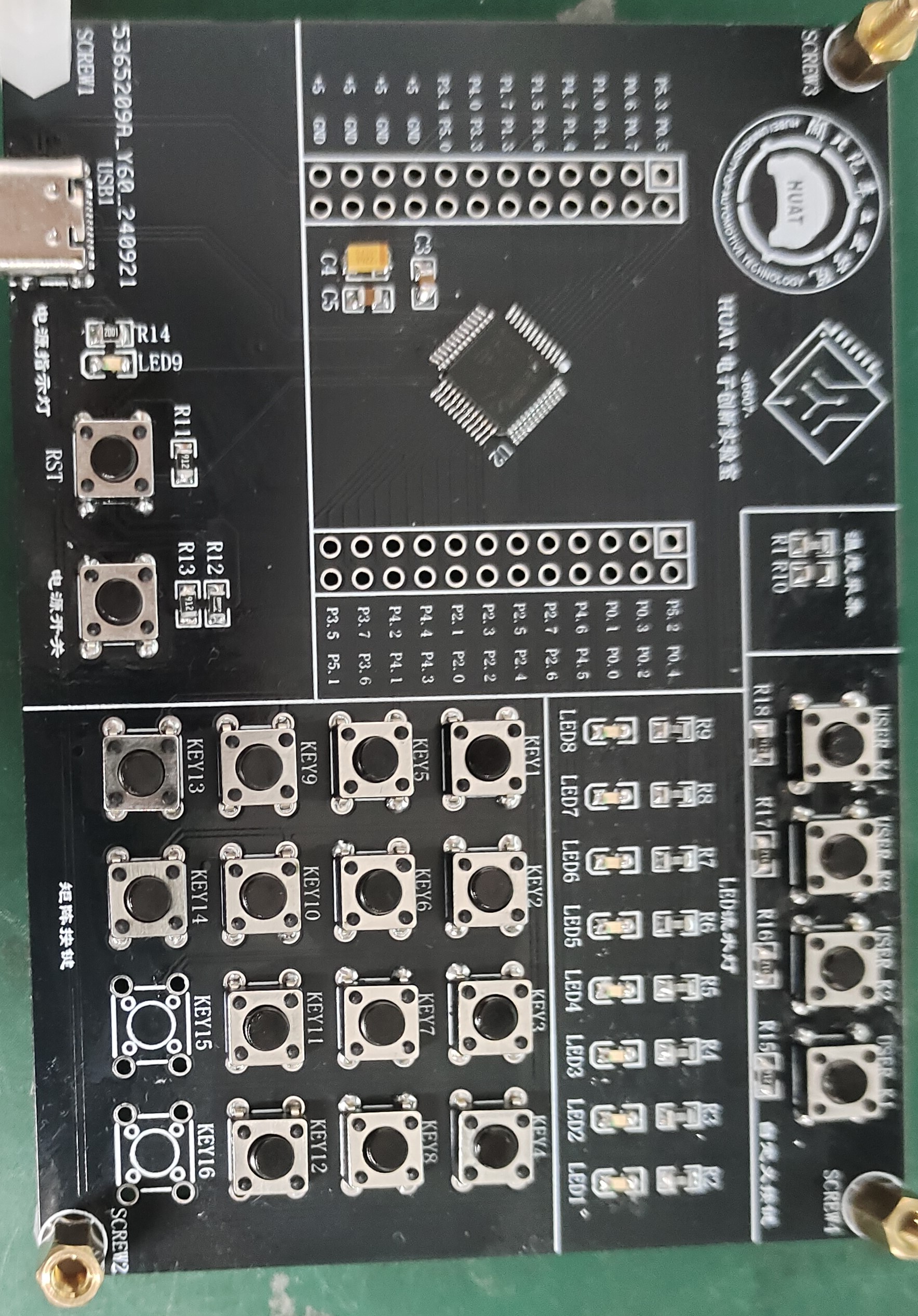
A niche embedded learning development board based on STC89C51
An embedded learning board based on the STC8H8K64U chip, suitable for people who want to use their brains a little but don't want to think too much.
Project Introduction:
This project is an embedded learning development board based on the 51 microcontroller, using USB-ISP mode for program download.
Project Functionality
: This design is an embedded learning board based on the STC8H8K64U microcontroller; it features four user-defined buttons, the functions of which must be determined by the user through corresponding code; it also has eight LEDs as running lights, which can be implemented through code to achieve a running light effect, and with further learning, a breathing light effect can be achieved. The onboard 44-matrix keypad can also be customized to perform many functions, making it suitable for beginners; additionally, an onboard thermistor, through the microcontroller's ADC, can be used to collect ambient temperature data, sufficient for use as the main controller in various systems.
Principle Analysis (Hardware Description):
This project uses the manufacturer's minimum chip system, plus LED lights, a matrix keypad, a download interface, user-defined buttons, and a thermistor. The microcontroller used in this project can be directly powered by a 5V power supply, so only a Type-C interface is included for power supply and downloading; no separate power supply is designed for the chip. The temperature acquisition uses a negative temperature coefficient thermistor, which can obtain the relationship between the sampling voltage and the ambient temperature according to the temperature curve, and is used to obtain the ambient temperature value. In addition, all IO of the microcontroller is brought out, and more peripherals can be connected.
Software code
include "led.h"
int i = 0;
float ls[8] = {0xFE,0xFD,0xFB,0xF7,0xEF,0xDF,0xBF,0x7F};
void LED_liushui(int dir)
{
if(dir == 1)
{
for (i=0;i<=7;i++)
{
P2 = ls[i];
delay_ms(100);
}
}
else if(dir == 2)
{
for (i=0;i<=7;i++)
{
P2 = ls[7-i];
delay_ms(100);
}
}
}
Simple running light code design, which will be updated later to make a small project
physical picture of ambient temperature acquisition.
video_20241008_164911_edit.mp4
PDF_A Niche Embedded Learning Development Board Based on STC89C51.zip
Altium - A niche embedded learning development board based on STC89C51.zip
PADS - A niche embedded learning development board based on STC89C51.zip
BOM_A Niche Embedded Learning Development Board Based on STC89C51.xlsx
91825
electronic


 京公网安备 11010802033920号

 15KP100A-TP


