This project
introduction
includes the following parts:
1. Schematic diagram of a three-port DC-DC converter (Problem C of the 2021 National Electronic Design Contest)
; 2. Schematic diagram of a single-phase AC electronic load (Problem A of the 2022 National Electronic Design Contest)
; 3. BOOST circuit;
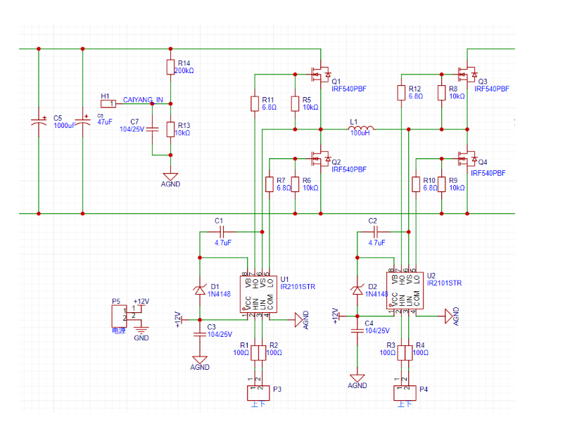
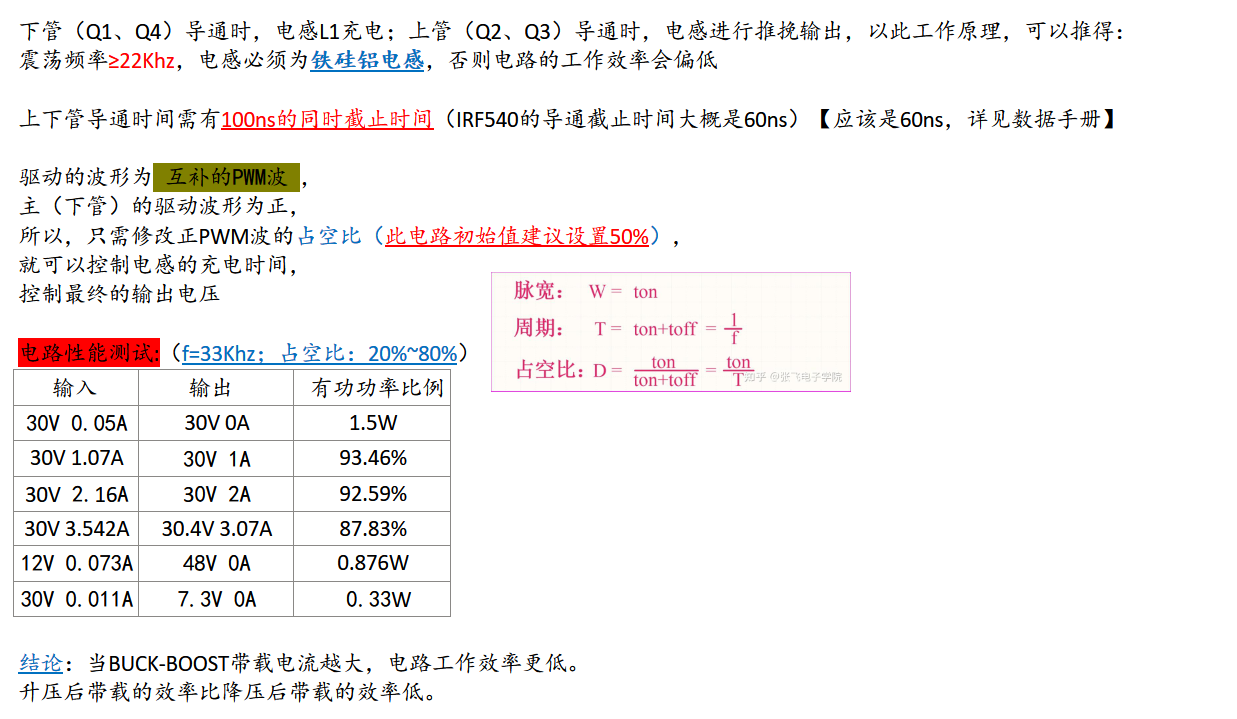
4. BUCK-BOOST circuit;
5. DC-AC converter;
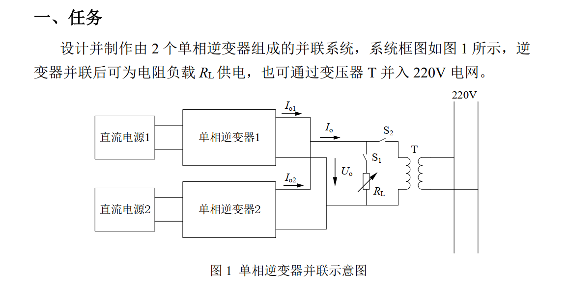
6. Schematic diagram of a single-phase inverter parallel operation system (Problem A of the 2023 National Electronic Design Contest).
Why only schematic diagrams? Because during the contest, things were rushed; PCB layouts were repeatedly drawn and deleted, and eventually lost. So please bear with it.
Note: When opening the project, first look at the readme. The program was written by my teammate, so there is no actual code! No code! No code! But there is a program logic!
==============================2023 Electrical Engineering Contest A Project Introduction================================
This project has not completed the advanced part, only the basic requirements have been met.
I. Project Requirements
Let's review the basic requirements of the 2023 Electrical Engineering Contest A Project.
1. Basic Requirements
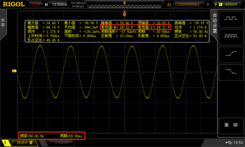
(1) Disconnect S2 and close S1, and use only inverter 1 to supply power to RL. When the effective value of the output voltage Uo is 24V±0.2V and the frequency fo is 50Hz±0.2Hz, the effective value of the output current Io is 2A.
(2) Under the working conditions of basic requirement (1), the total harmonic distortion (THD) of the output AC voltage is not greater than 2%.
(3) Under the working conditions of basic requirement (1), the efficiency of inverter 1 is not less than 88%.
(4) With S2 open and S1 closed, only inverter 1 supplies power to the load. When Io varies between 0A and 2A, the load regulation rate SI1 ≤ 0.2%.
II. Overall Design Block Diagram and Description

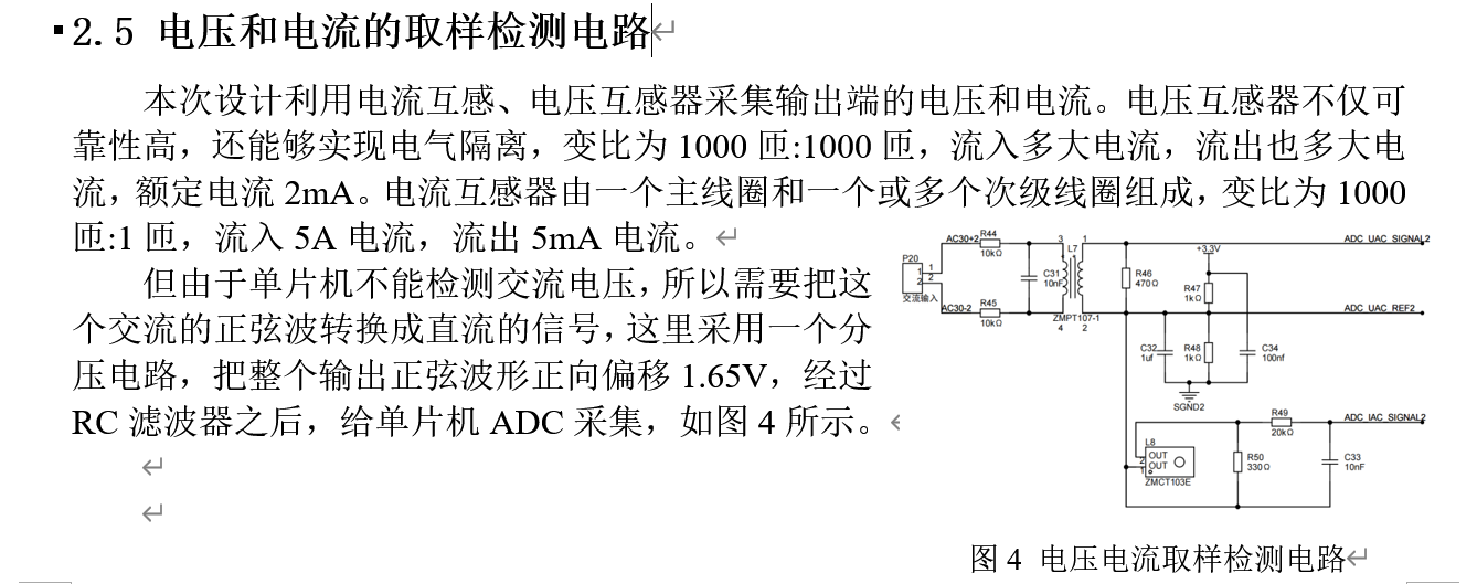
III. Hardware Circuit Description

IV. Software Part and Output Results
Software Part:
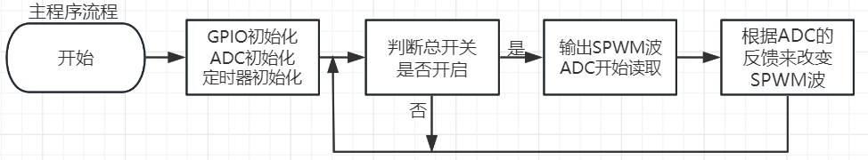
(1) Program Function Description
The microcontroller is made into an automatically adjustable SPWM wave generator that can stably output voltage and maintain communication with the specified circuit.
(2) Program Design Ideas
To complete the design of the single-phase inverter parallel operation system in this paper, not only hardware design is required, but also software design. In order to realize the various functions of the microcontroller, the compilation of software programs is indispensable. This system uses C language to write programs and Keil5 DMK as the integrated development environment.
Dividing a sine wave with F=50Hz and T=20ms into 200 equal parts, we know that each part is 1/(200*50)=0.1ms=100us.
Therefore, by modifying the width of the PWM wave every 0.1ms, a sine wave similar to an SPWM wave can be output, as shown in the figure below.

The microcontroller configuration is as follows:
Set the total system clock frequency to 48MHz;
use advanced timer TIM1 to output a 20kHz dual-channel complementary PWM wave with dead time as the carrier of the SPWM;
use general-purpose timer TIM2 to perform time-division processing of the program, and run the corresponding program when the time reaches the corresponding time to ensure the program runs in an orderly manner;
use general-purpose timer TIM3 to change the width of the PWM wave every 0.1ms as the fundamental wave of the SPWM, and read the ADC value and feed it back to the microcontroller for peak adjustment of the SPWM wave;
use ADC1 group, and use the 4 ADC channels in the group to read the values of voltage, current, etc.
Output Results:
V. My Own Notes

=== ... =============================BUCK-BOOST Circuit Description= ...


 京公网安备 11010802033920号

 C420C109K5G5CA


