This 12.6V (3S) lithium battery charger, based on the Ingenic IP2326 chip, uses the Texas Instruments INA219 to collect and display current and voltage data, and features practical functions such as nighttime light-off functionality.
INA219: Current and voltage measurement; FD1642: Digital tube driver (seems somewhat niche?).
The board technology is fairly standard; relevant materials are attached. The following mainly introduces the unique features of this project.
allowing users to execute different commands through short, medium, and long presses, reducing the number of function buttons. The selected command is displayed via indicator lights.
• Medium press (both indicator lights on): Turns IP2326 charging on/off;
• Long press (both indicator lights off): Turns off all board lights (short press restores), while retaining charging enable;
• Supports complete board light-off
for use in low-light environments.
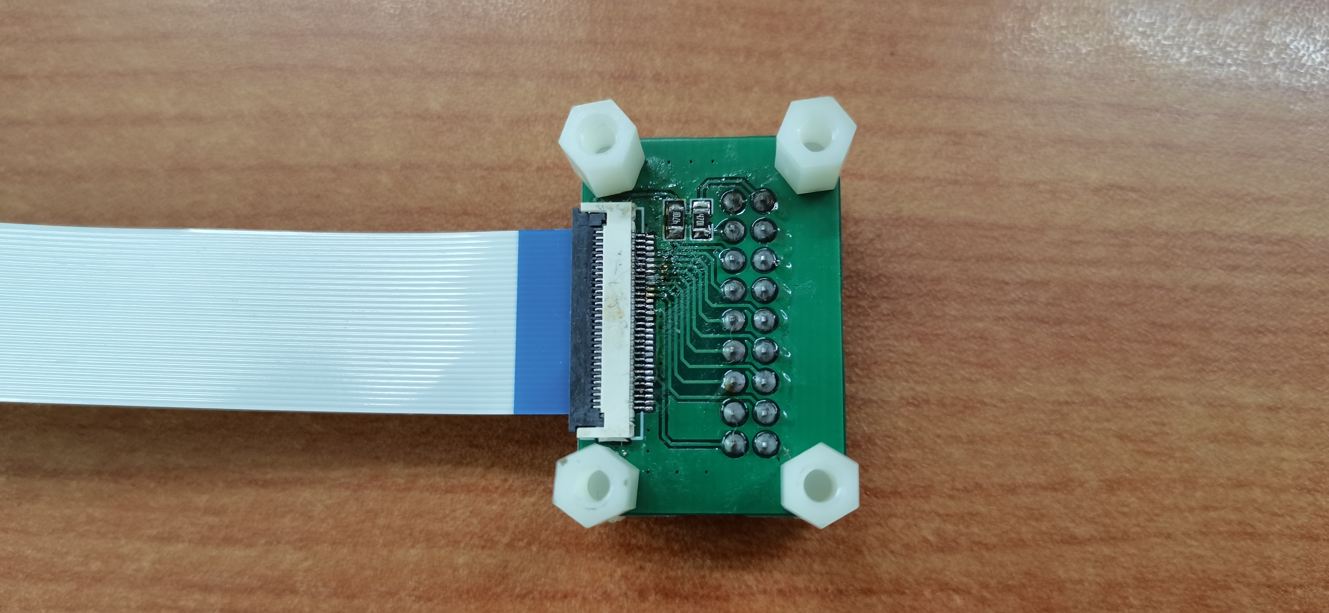
The STM32H7S78-DK development board has a 30-pin camera interface, while the Zhengdian Atom OV5640 camera module has 2*9 pins. Therefore, an adapter module is needed to convert the 30-pin interface to a 2*9 pin interface.
This is a simple circuit board with basic LEDs and resistors, making it very helpful for beginners to learn the PCB design process. The unique border design makes the simple circuit board look more interesting.
1. The entire design uses through-hole components such as diodes, pin headers, and resistors, making it easy for beginners to solder.
2. It uses pin headers for power-on, operating at 3.3V, making it simple, clear, safe, and stable.
3. Different board frame designs are available, and holes can be drilled for use as mounting brackets.
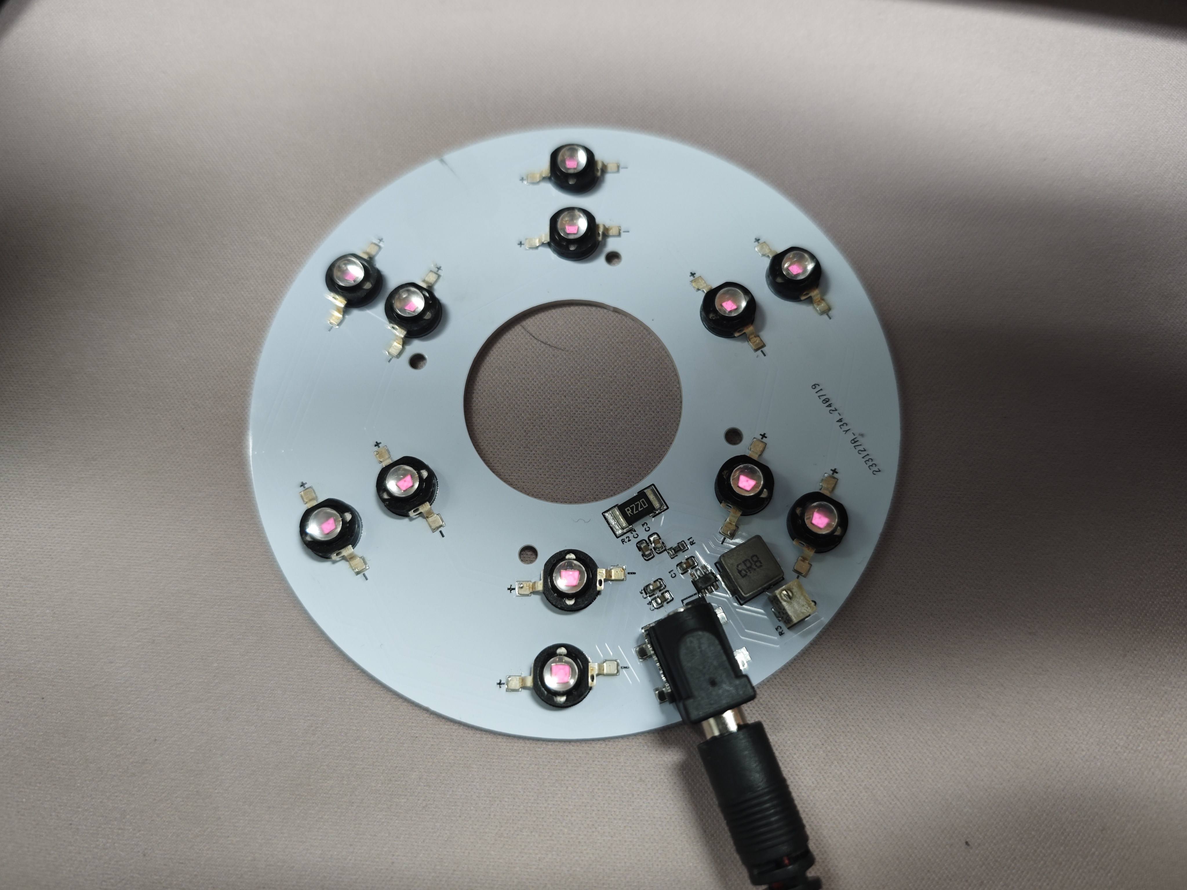
This constant current LED driving solution is based on TI's TPS92200 LED driver chip. It uses a 12V voltage input and supports a maximum current output of 1.5A. The LED brightness can be adjusted by twisting a potentiometer. The aluminum substrate provides good heat dissipation.
Project Overview:
This project presents a constant current LED driving solution based on TI's TPS92200 LED driver chip. It can achieve a 4-30V input and a maximum current output of 1.5A. LED brightness can be adjusted by changing the potentiometer value. The solution uses 12 infrared LEDs, but other LEDs can also be used. The inductor value and feedback resistor can be adjusted according to the LED's on-state voltage, current, and ripple. It is suitable for experiments or lighting needs in night vision applications. The TPS92200 supports overvoltage protection, short-circuit protection, and overheat protection.
Project Parameters:
This design uses the TPS92200 LED driver chip, supporting brightness adjustment via voltage sampling or PWM output. This solution uses analog voltage sampling, with an analog dimming range of 5%-100%.
The driver board uses a DC 5.5 interface with a 12V input voltage. The LED voltage drop is 1.7V, with three series and four parallel configurations, each channel providing 100mA of current. The single-sided aluminum substrate offers better heat dissipation compared to the FR4.
The selection parameter calculation example
can be adjusted according to your needs. Parameter
values
:
Input voltage range: $V_{VIN}$
12V $pm$ 10%
LED forward conduction voltage drop: $V_{LED}$
1.7V
Output voltage: $V_{OUT}$
5.2V (1.7V*3+0.099V)
Maximum current per LED:
300mA
Sum of maximum LED currents: $I_{LED}$
1200mA
Inductor current ripple: $K_{IND}$
30% Maximum LED current
LED current ripple: $I_{LED(ripple)}$
20mA or less
Input voltage ripple: $V_{VIN(ripple)}$
200mV or less
Dimming type:
This project uses analog dimming, selecting TPS92200D1.
$K{IND}$ is usually between 0.2-0.4. The smaller K{IND} is, the smaller the output current ripple. Here, 0.3
FB is selected. The reference voltage at the pin is fixed, with the voltage between FB and GND being 99mV. The voltage of FB is adjusted between 5mV and 99mV by adjusting the value at the DIM pin.
The feedback resistor determines the maximum current. The feedback resistor calculation formula is:
$$
R{SENSE} = frac{V{FB_REF}}{I{LED}} = frac{99mV}{1.2A} = 0.0825Ω
$$
The inductor calculation formula is
: $$
L=frac{V{OUT}(V{VIN(max)}-V{OUT})}{V_{VIN(max)}K{IND}*I{LED}f_{sw}}=frac{5.2V(13.2V-5.2V)}{13.2V0.31.2A*1MHz} = 8.75uH
$$
TI recommends that the inductor current ripple be greater than 300mA. The inductor current ripple calculation formula is:
$$
I{L(ripple)} = frac{V{OUT}(V{VIN(max)}-V{OUT})}{V_{VIN(max)}Lf_{sw}} = frac{5.2V(13.2V-5.2V)}{13.2V8.75uH1MHz} = 360 mA
$$
If the LED ripple requirement is not high, the maximum brightness can be changed directly by modifying the size of the feedback resistor without affecting the implementation of basic functions. This solution uses a 0.22Ω feedback resistor, and the actual current per channel is approximately 110mA.
Note:
This solution uses a single-layer aluminum substrate for prototyping. The bottom surface of the aluminum substrate is conductive. Care must be taken not to select the wrong package for the adjustable resistor and DC power interface. This solution uses single-sided surface mount packages throughout.
The actual product image
shows a light board using 850nm infrared LEDs.
PDF_Constant Current LED Driver Board Based on TPS92200.zip
Altium_Constant Current LED Driver Board Based on TPS92200.zip
PADS_Constant Current LED Driver Board Based on TPS92200.zip
BOM_Constant Current LED Driver Board Based on TPS92200.xlsx
91875
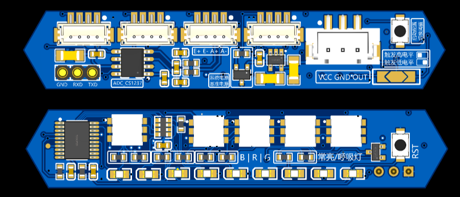
Air001 + AD conversion chip + strain gauge for 3D printing heated bed leveling
A simple and low-cost 3D printed pressure-sensitive heated bed leveling solution, compatible with HX71708 or CS1237, with a high sampling rate of 320 or 1280Hz.
This program obtains
a 3D printer pressure heated bed. The main controller uses PY32F002AF15P (Puran) and Air001 (Hezhou), which are essentially the same. The Arduino development environment is provided by Hezhou, and it can use either HX71708 or CS1237 (recommended) AD conversion chips.
The circuit is simple and easy to modify, and can be easily embedded into various other motherboards or project circuits.
Chip selectable data rates:
HX71708 10, 20, 80, 320
; CS1237 10, 40, 640, 1280.
The basic version

adds an RGB version with
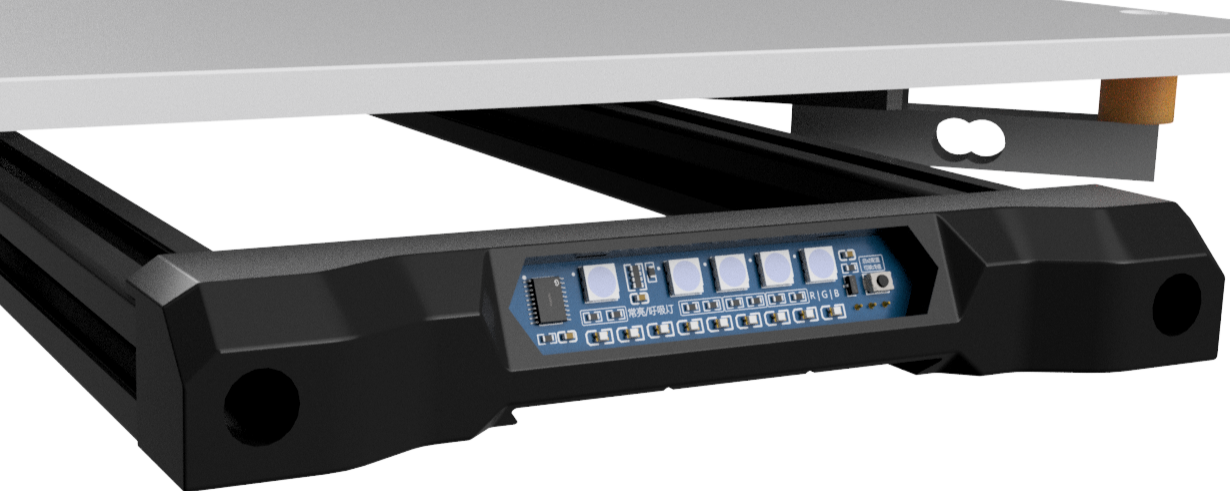
a 5-level LED progress bar display function, triggering progress to convert to percentage, controlling LED lighting from 30-100%.
One logo light, four text background lights, resistor jumper settings for color and constant or breathing light selection.
An external reference source chip can be used, or a 20R resistor can be used with an LDO as the reference source. An external reference source provides greater accuracy and stability.
At 1280Hz, the weight reading jump can be reduced from 30g to approximately 10g, resulting in a lower threshold and greater stability.
Refer to
the RGB lighting instructions for

the trigger logic. The trigger logic
reads the pressure sensor data from the ADC chip in real time and converts it into a pressure value. At a maximum rate of 1280Hz,
a pressure value exceeding the filtered value triggers a level change in the two output pins. There is a maximum time limit; after exceeding this limit, the threshold is updated, returning to the non-triggered state.
The current static pressure value + preset threshold = trigger threshold. If there is no
sudden pressure change after a certain time, the trigger threshold is updated once. Slow increases or decreases in pressure over a long period will not cause false triggering; only sudden changes exceeding the preset threshold will trigger the trigger.
Test conditions: CS1237 1280Hz, 5mm/s speed, belt Z 80:20 reduction ratio, trigger weight 150g.
Accuracy test results after 10 consecutive repetitions:
Range
Deviation
0.0025.
0.001146
0.0025
0.001146
0.0050
0.001581
0.0050
0.001581
0.0025
0.001000
0.0075
0.001871
0.0050
0.002000
0.0050
0.001658
0.0050
0.001581
0.0050
0.001346
Klipper officially recommends that the repeatability range of the leveling probe be within 0.025. If using the HX711 with a maximum data rate of 80Hz, the speed must be reduced to barely meet this requirement. The high sampling rates of the HX71708 and CS1237 can significantly improve repeatability to obtain better probe data.
If the test results show a range value greater than 25 micrometers (0.025 millimeters), then the probe does not meet the accuracy requirements of a typical bed leveling procedure. Adjusting the probe speed and/or the probe start-up height can be tried to improve probe repeatability.
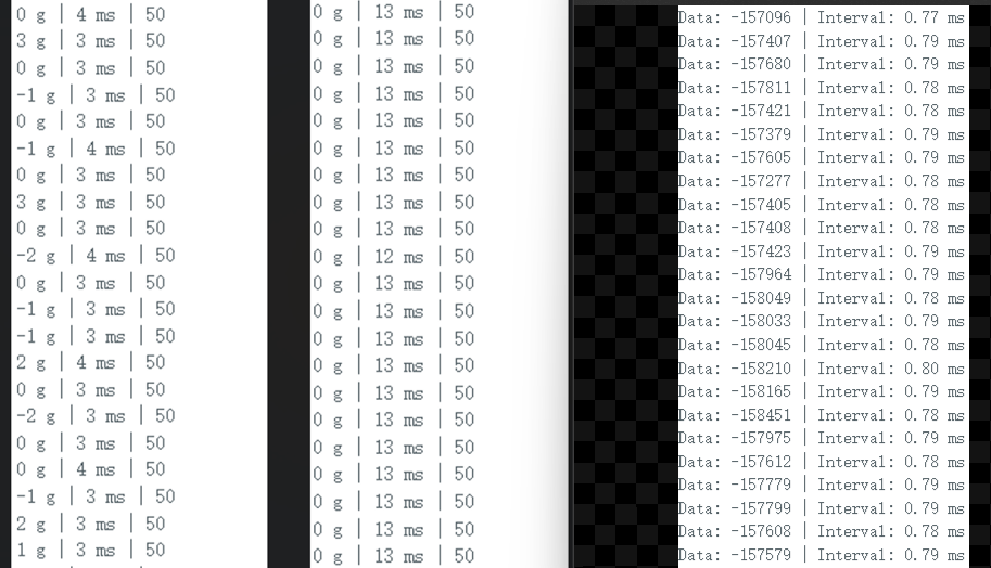
Comparing the data intervals of HX71708 (80Hz and 320Hz) and CS1237, the
download instructions
require a separate serial port programmer. Connect the pre-installed serial port pin header for downloading.
Configure the development environment according to the official tutorial of Hezhou. Air001 Arduino-based user manual
[Important]: Set the main frequency to 48MHz during download.

Program description:
All programs are from ChatGPT4.
Modify the code by using `const int THRESHOLDS[] = { 50, 150, 300 };` to customize the trigger threshold weight. The boot button can be used to switch during operation. Set
the serial port baud rate to 115200. Other settings and debugging can be modified using serial port commands.
Send HELP via serial port to get help information
using the command: `SET SPEED index`. This takes effect after restarting. This is used to modify the CS1237 data rate. Lowering it will result in a more accurate weight. 0=10, 1=40, 2=640, 3=1280.
Send the command `ADC value` via serial port. This value is a calibration factor used to convert the ADC (Analog-to-Digital Converter) reading into the actual weight. Different sensors will produce different results; you will need to test and modify the settings to obtain an accurate weighing result.
Use the command to enable SERIAL serial port output. The serial port will then continuously output the current weight reading in real time. Weigh an item of known weight, observe the reading, and adjust the calibration factor until the reading is close to the actual weight of the item. [Important] The air001's performance is insufficient for stable operation with serial port output at sampling rates above 640Hz. Use it only during debugging at a lower sampling rate. Be sure to disable it at high sampling rates
. Debugging instructions:
The SERIAL command enables real-time weight reading output, outputting three data points every 100ms: weight, filtered weight, and trigger threshold.
After enabling SERIAL output, you can use the Arduino IDE's serial port plotter to visualize the data using charts.

The RECORD command starts recording the highest and lowest weight readings, which can be used to observe reading fluctuations under no-load conditions or trigger force.
EMA is used to enable or disable the exponential moving average filter. This option is not saved after setting and is enabled by default.
These features are only available in the CS1237 version code; they are deprecated in HX71708. The following content is for reference only and is not recommended.
The HX711 library does not support modifying the data rate in HX71708. HX71708 has only one channel with a fixed gain, and the data rate is modified through code. HX711, however, modifies the rate through hardware and modifies the gain through code. Therefore, you need to modify the `scale.set_gain(64)` function in the `hx711.cpp` library file

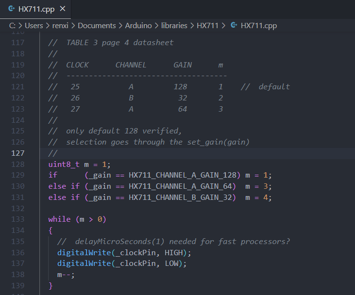
to set the gain, and then set the corresponding gain in `cp`. Changing the pulse count in the p library file to 4 enables data rate control.
The HX711 program uses absolute pressure values for judgment; triggering occurs when the pressure exceeds a threshold, and the reading resets to zero periodically.
The CS1237 uses relative pressure values for judgment, enabling dynamic detection of sudden pressure changes without resetting to zero. Triggering occurs when the real-time pressure value exceeds the reference value plus the threshold; the reference value is updated periodically. Slowly increasing weight reaching the threshold will not trigger a trigger.
Both use the Boot key to switch preset thresholds in the code
, outputting two opposite high and low level signals. For shorting jumpers,
it is recommended to use the CS1237, which is relatively cheaper, has better performance, and offers richer code debugging features.
Air001_CS1237.zip
Pressure board compilation, burning, and calibration.mp4
Trigger Demo - Compressed with FlexClip.mp4
SJ-VORON-BED-HANDLE-B_1.step
PDF_Air001 + AD conversion chip + strain gauge for 3D printing heated bed leveling.zip
Altium_Air001 + AD conversion chip + strain gauge for 3D printing heated bed leveling. zip
PADS_Air001 + AD conversion chip + strain gauge for 3D printing heated bed leveling. zip
91876
VL812&VL813_USBHUB
A USB 3.0 HU based on VL812 and VL813
Video Link:
Bilibili Video -- Function Demonstration and Introduction
Project Overview
This project is a replica of the original Bilibili video above.
Physical Images :
Figure 1: Soldering Completed
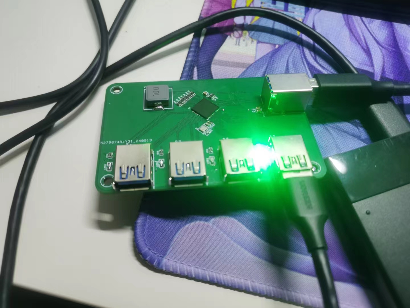
Figure 2: Printed Shell
Figure 3: Assembly
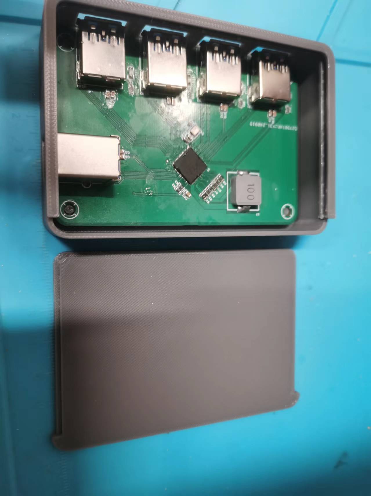
Figure 4: Hole Alignment Perfect
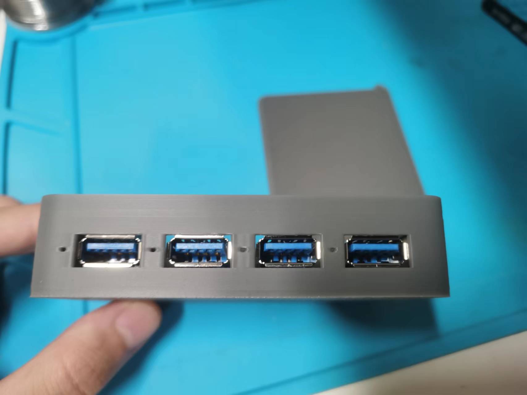
Figure 5: Read/Write Speed is also Acceptable
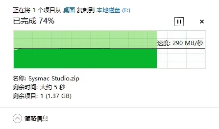

Overall, it's a successful replica.
Notes :
1. I used that large inductor for the 1.2V section because I happened to have it, so I used that package. Replicas don't necessarily need to use the same one.
I didn't use Type-C because I'm too inexperienced to solder a 24-pin connector (sad).
426108b36987efedaf002bc5693560cd.mp4
C717656_C794990C4FCEACD348FF18061C8910B8.pdf
E4BC62D5D5AF0E9F08F4D7C610B0A88D.pdf
3DShell_PCB1.zip
PDF_VL812&VL813_USBHUB.zip
Altium_VL812&VL813_USBHUB.zip
PADS_VL812&VL813_USBHUB.zip
BOM_VL812&VL813_USBHUB.xlsx
91877
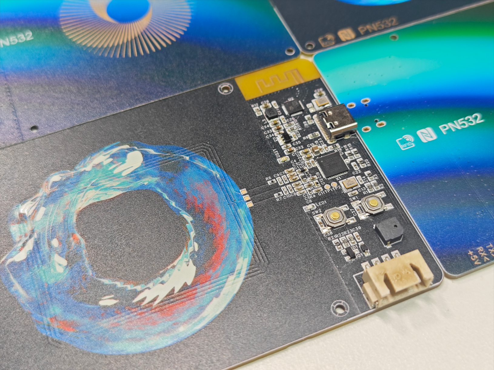
Color silkscreen PN532 CH582 NFC card reader
The PN532 NFC card reader with CH582 uses JLCPCB's color silkscreen printing process and can connect to a host computer via USB serial port, simulated keyboard, or BLE, or be used to develop serial screen applications based on CH582.
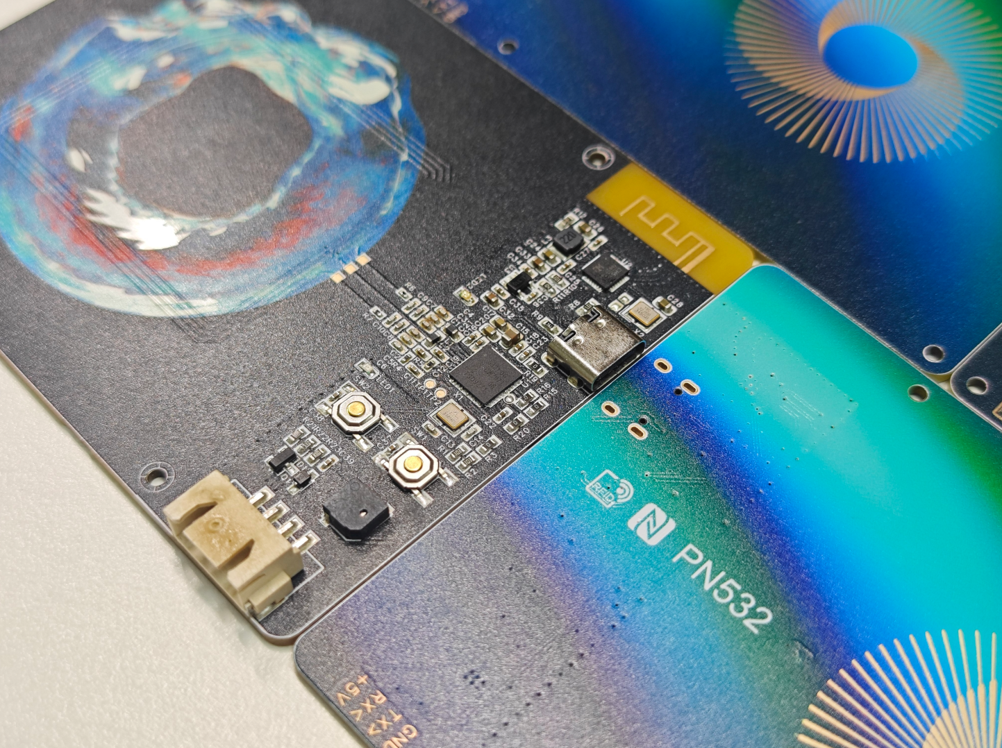
In August, I received a free color screen printing voucher from JLCPCB. Seeing that most color screen printing projects on the JLCPCB open-source platform were microcontroller core boards or simple NFC cards, I designed this PN532 + CH582 card reader to make the most of this voucher (it needed both circuitry and a large area for color screen printing). Other PN532 projects on the JLCPCB open-source platform either directly expose the PN532's serial port or add a CH340, requiring dedicated host computer software. This project adds a CH582 to the PN532, allowing connection to a host computer via USB CDC serial port or BLE, or direct interaction between the CH582 microcontroller and the PN532. It also exposes a four-wire XH2.54 interface for serial displays, enabling the development of more applications.
The circuit design
uses the NXP PN532 chip, supporting multiple protocols such as ISO14443A/B, FeliCa, and NFCIP-1. It supports card reading, writing, and card emulation functions
, connecting to the main controller via UART, SPI, and I2C interfaces. This project uses a UART interface to connect to the CH582.
The PN532 chip on Taobao costs around 9 RMB, but there's a risk of counterfeit products (even from highly-rated shops) being unusable. It's recommended to buy a pre-built module for around 10 RMB and disassemble the chip.
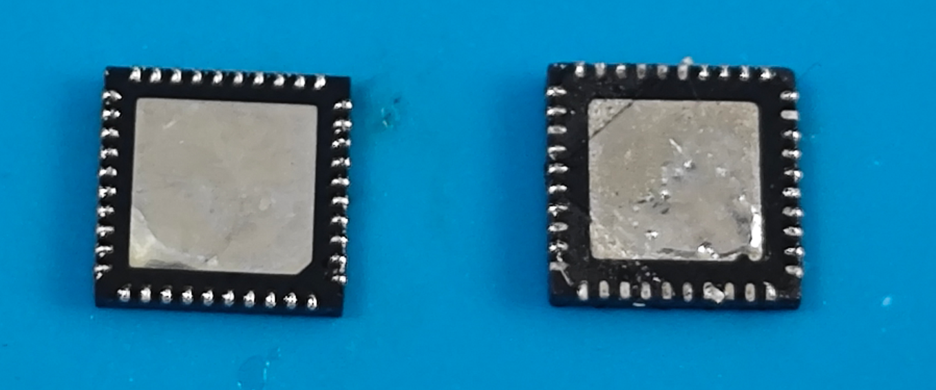
The left side shows a usable PN532 chip removed from a PN532 module; the right side shows a 9 RMB chip from a certain shop, with obvious signs of polishing and solder oxidation, unusable on the board. Note the different shape of the bottom heatsink pad in the lower right corner. For debugging, test the 26-pin RSTOUT_N test point. After the chip completes reset, it should be 3.3V; if it remains at 0V, the chip or crystal oscillator is faulty.
The antenna matching circuit layout references NXP's AN10688, and the capacitor and resistor values are based on yizhidianzi's engineering specifications. The measured sensing distance is approximately 4-5cm.
The PN532 crystal oscillator frequency is 27.12MHz, a less common model. Note that
the WCH CH582F low-power Bluetooth MCU chip has 32KB RAM and 512KB Flash, and two USB FS OTG controllers.
Only one USB port is actually used; it can be replaced with CH573F or CH571F, but the price is similar, around 2-3 yuan.
Firmware can be downloaded directly via USB without a programmer: Install WCHISPStudio, press and hold the SW1 button while inserting the USB into the computer, then select the firmware file in WCHISPStudio and click download.

The two-wire simulation interface is brought out to the SBU pin of the Type-C interface according to the project's scheme. Although there is currently no suitable debugger, the debug interface can be manually brought out using a Type-C test board. The
BLE antenna design is related to the board thickness. This project uses a 1.6mm board thickness.
The board is equipped with an MLT-5020 buzzer, which can be controlled by the TMR0 PWM output of CH582.
The color silkscreen image is from Unsplash and can be used for free commercial purposes. Front image, back image.
The color silkscreen is not heat resistant. I used a 260-degree reflow oven for soldering, and it turned a little yellow. It is recommended to use a lower temperature.
All components are surface mount. There are no protruding insertion holes on the bottom. The board can be placed flat on the table.
Firmware
. The firmware provided in this project is based on the WCH official example with simple modifications. It is relatively rudimentary. You can modify it as needed. The firmware functions are as follows:
When directly plugged into a computer's USB port, the red light illuminates, indicating that the CH582 will recognize it as a USB HID keyboard. When an ISO14443A card is detected, the blue light illuminates, a buzzer sounds, and it automatically reads the card's UID and simulates keyboard input of the UID, followed by pressing Enter, similar to the function of a barcode scanner.
Holding down the SW2 button while plugging into the computer's USB port will cause the CH582 to emulate the CH340 chip, recognizing it as a USB CDC serial port. It can be used with various PN532 serial port host computer software. Other PN532 projects on LCSC Open Source provide host computer software. The red and blue lights will flash alternately during data transmission and reception.
Press and hold the SW1 button while inserting the USB cable into the computer to enter ISP mode. You can download the firmware (the firmware is ch582-hid-cdc.hex, and the ch582-hid-cdc.zip file is the source code) via WCHISPStudio.
I tried using WCH's BLE serial port pass-through example, and it was possible to achieve BLE serial port pass-through through the WCH BLE Tool Android APP, but it didn't appear in the MTools BLE device list. This might be due to a different Feature ID; a compatible board is needed.
Refer to
other PN532 projects from LCSC , such as
the Hakurei Reimu project. The attachment contains the host computer software LiiGuang. More pictures
of the host computer software are also attached.


ch582-hid-cdc.hex
ch582-hid-cdc.zip
PDF_Color Silkscreen PN532 CH582 NFC Card Reader.zip
Altium_Color Silkscreen PN532 CH582 NFC Card Reader.zip
PADS_Color Silkscreen PN532 CH582 NFC Card Reader.zip
BOM_Color Silkscreen PN532 CH582 NFC Card Reader.xlsx
91878
electronic


 Furthermore, in the adapter board design, to ensure the stability of the relevant electrical characteristics, a 100nF decoupling capacitor needs to be added to the OV5640 power supply terminal, and 4.7kΩ pull-up resistors need to be added to the SCL and SDA IIC interfaces. The
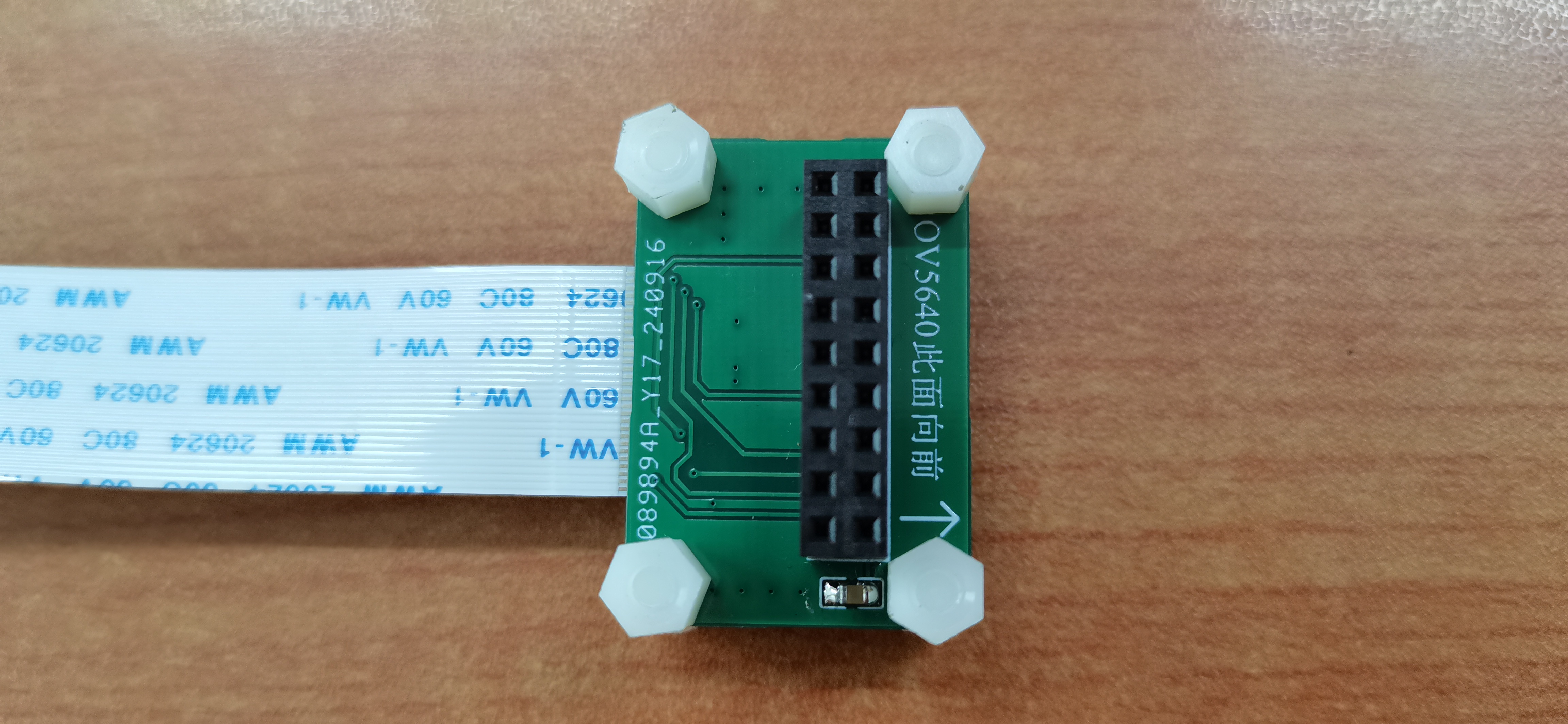
 document contains the relevant code for the camera.


 京公网安备 11010802033920号

 GS84032B-180I


