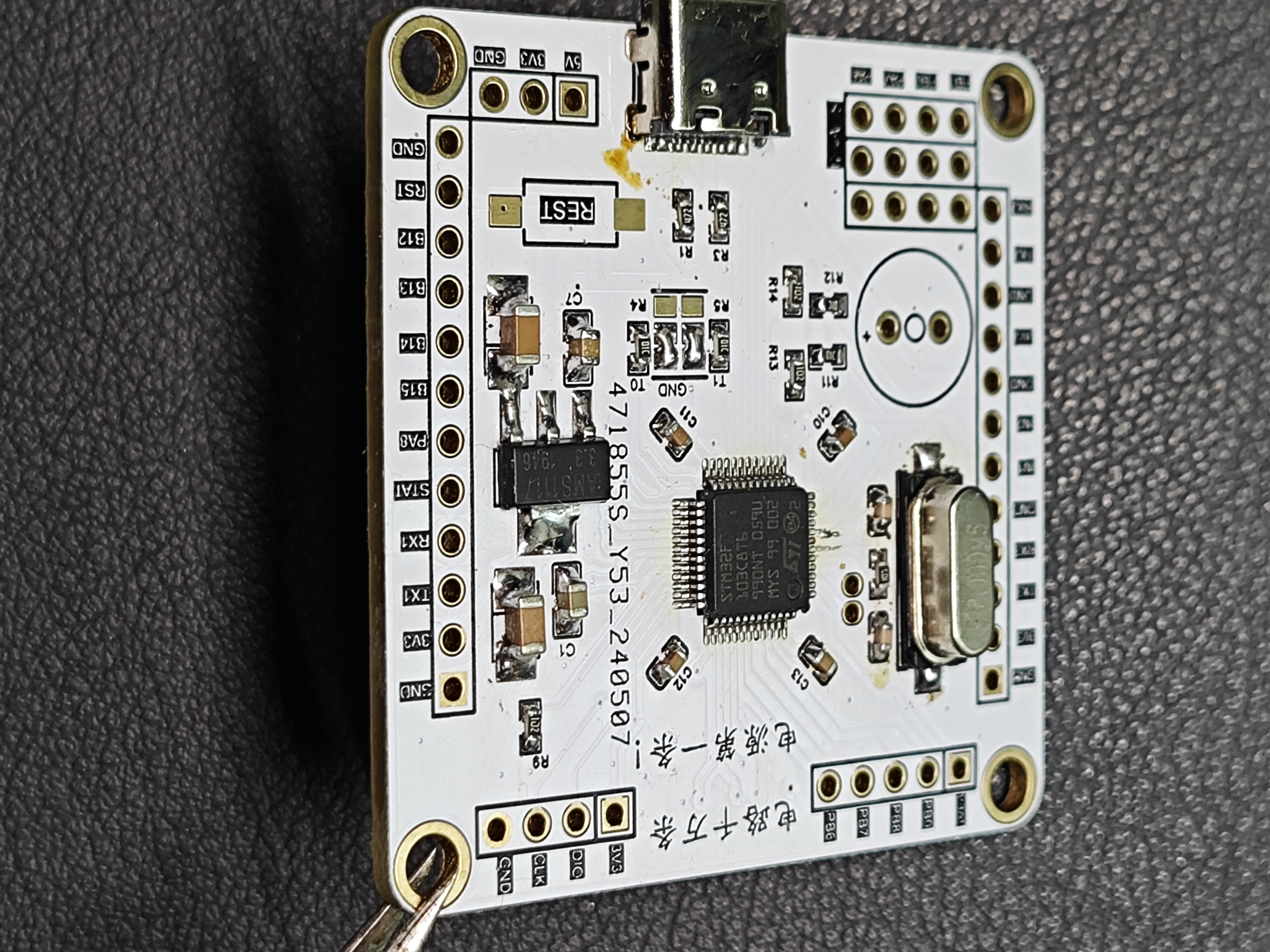
: 1. Integrated C8T6 minimum system, pin compatible with 2.54mm perforated boards;
2. Onboard TYPE-C power supply port and CH340 serial port;
3. Active/passive buzzer;
4. Two sets of 3 LEDs, one set of general I/O, one set of PWM;
5. Integrated NRF2401 2.4G module small board interface;
6. Integrated JDY-31 series Bluetooth module interface;
7. Hardware IIC/UART3 interface
; 8. One set of PWM servo interface;
9. AMS117 3.3V voltage regulator circuit ;
10. BOOT selection solder jumper
; 11. Front pin header compatible with 2.54mm perforated boards, back pin layout mimics flight controller soldering points
according to function, dimensions 46.5mm*46.5mm. Current testing
everything is normal, perforated board compatible, very suitable for testing.
pin configuration as shown .
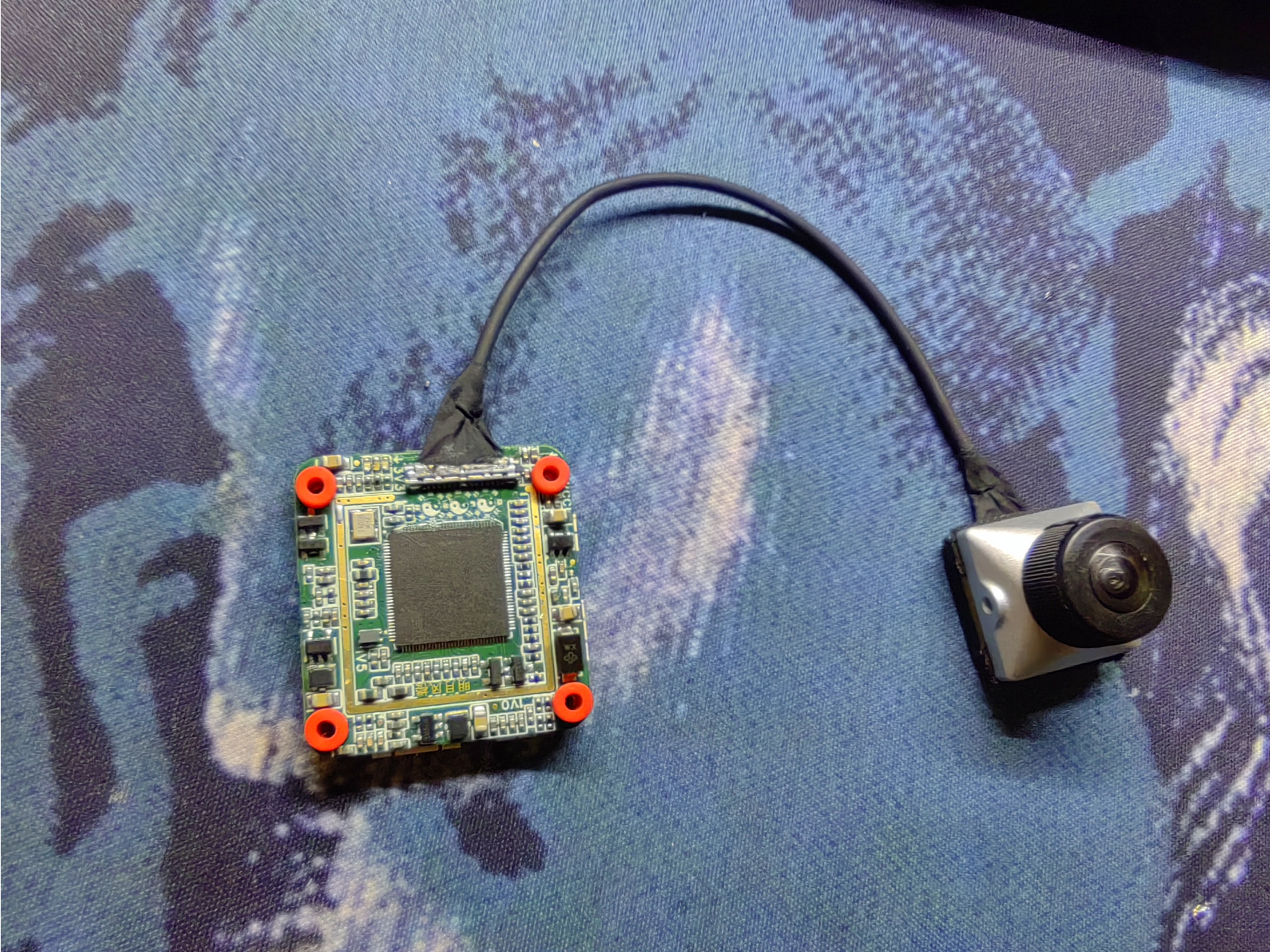
OPENIPC uses the Sony IMX415 connector DF56, a definition defined by domestic enthusiasts (consistent with the side definition, interchangeable). It is incompatible with DJI, Runcam, and other manufacturers.
Verified, no issues.
This board uses components in 0402 and higher packages (except LDOs, some are really small).
JLC06161H-3313 (free/finished board thickness 1.60mm±10%).
This project has high soldering difficulty; beginners are not recommended to replicate it. (It's only slightly simpler than the one next door, since it's mostly single-sided). For
those who want to save money, overcome difficulties, and love tinkering, you can give it a try.
Sellers on Xianyu recommend mass production to drive down the price; you can try it.
Sellers are encouraged to engage in price wars. First come
, first served. DIY is risky; please order with caution. The author is not responsible for any unexpected events or losses that may occur.
DigitalFPV Technical Exchange Group 904031209.
This is a technical exchange group! Not an OPENIPC after-sales group! Manufacturer after-sales issues will be kicked out!
Yes, the above text is basically directly copied from the side QVQ, because I really don't know how to write it...
First, I tried to use a single-sided layout for this board. The back only has a DF56C solder pad, which you'll need to manually solder (the DF56C pads are already stretched).
Second, solder the LDO and resistors/capacitors first. After soldering, use a multimeter, connecting one side to 3.3V and the other to the LDO output, to check for resistance. If there's no resistance, congratulations, you have a cold solder joint. Resolder
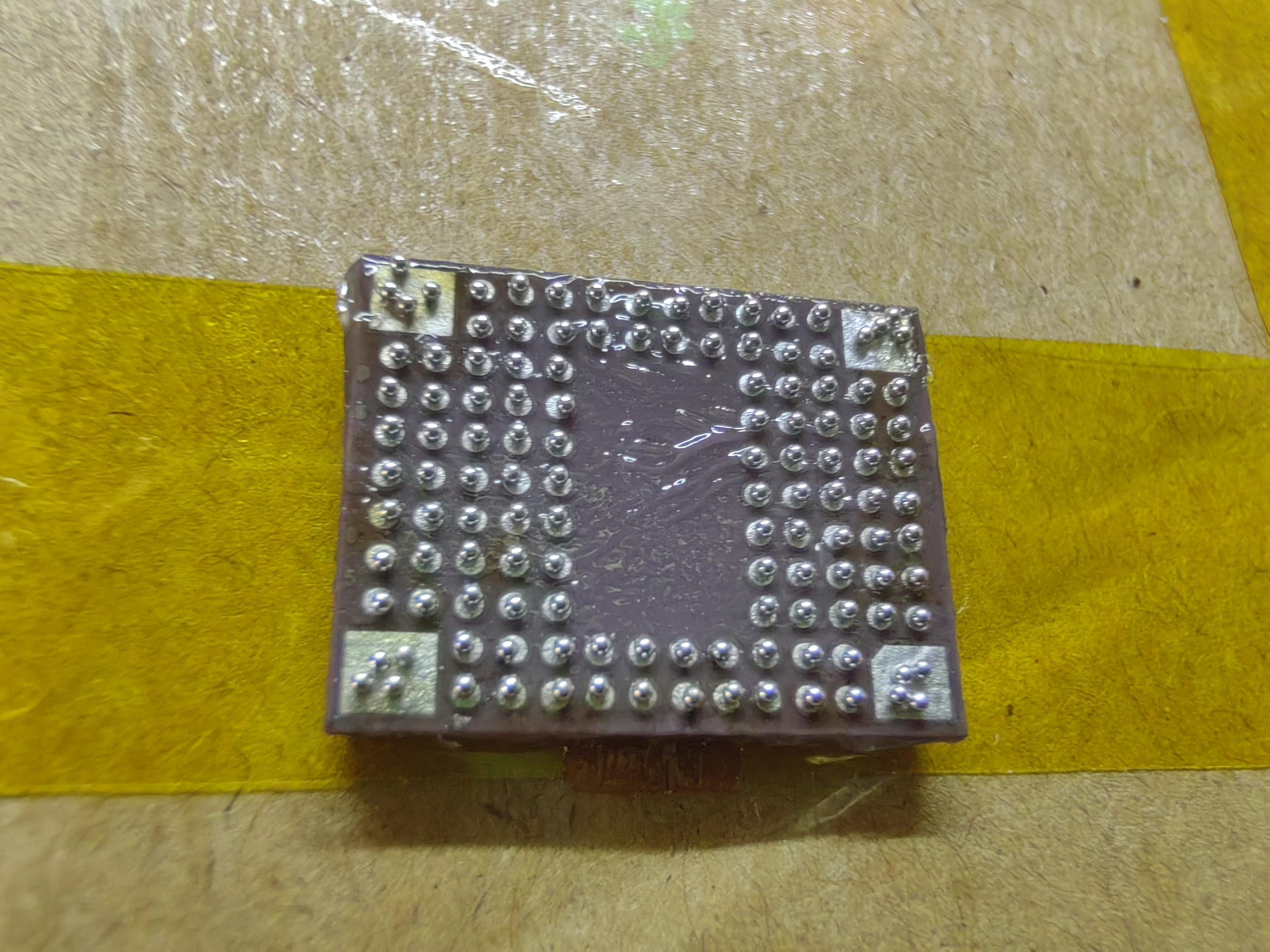
the LDO using a hot plate or hot air gun. After soldering the LDO, start soldering the 415. For the 415, I suggest first adding solder balls, applying a layer of solder flux (not too thick), and then slowly dotting the solder balls (I used 0.4mm). After blowing with a hot air gun, apply a layer of solder flux to the PCB, place it on a hot plate (heating platform), and gently push it to automatically reset it to stop heating (you can reverse this and place solder balls on the PCB).
For testing, the MIPI DPDN (the 8 external wires) uses a multimeter to measure the resistance to ground. If there is resistance, there's no problem; otherwise, it's a cold solder joint. For the low-speed 4 wires (mclk, RST, I2C), ground the positive terminal of the multimeter and then measure the negative terminal. If the resistance is still the same, there's no problem.
Connect it to the 338, power it on, and if the 415 heats up, the low-speed 4 wires are fine. See the DPDN diagram for more information. If the DN (around 0.5V, measurable with a multimeter) isn't heating up, then there's a problem with the four low-speed pins. Check if the I2C has 1.8V, etc. For
the DF56C, I recommend using a soldering iron; it's brittle and easily deformed. During soldering, absolutely avoid dripping solder onto the socket, otherwise you'll have to replace it.
Actually, the 415 is much easier to solder than the 335. You can use an Aurora case, but some components are too close to the case, so I suggest using adhesive tape or something similar to wrap the LDO, capacitors, and resistors to prevent them from short-circuiting and burning out. After finally getting it working, you install the case, and lo and behold, it's short-circuited and dead
! Using immersion gold plating, 3133 (free), 1.6mm (JLC06161H-3313 (free/finished board thickness 1.60mm±10%)).
Finally, I hope everyone can get their hands on this open-source image transmission system (I dare not open 338... opening it causes a lot of trouble, I believe you can draw it yourself).
Too much solder paste was applied here, which caused me to resolder it later
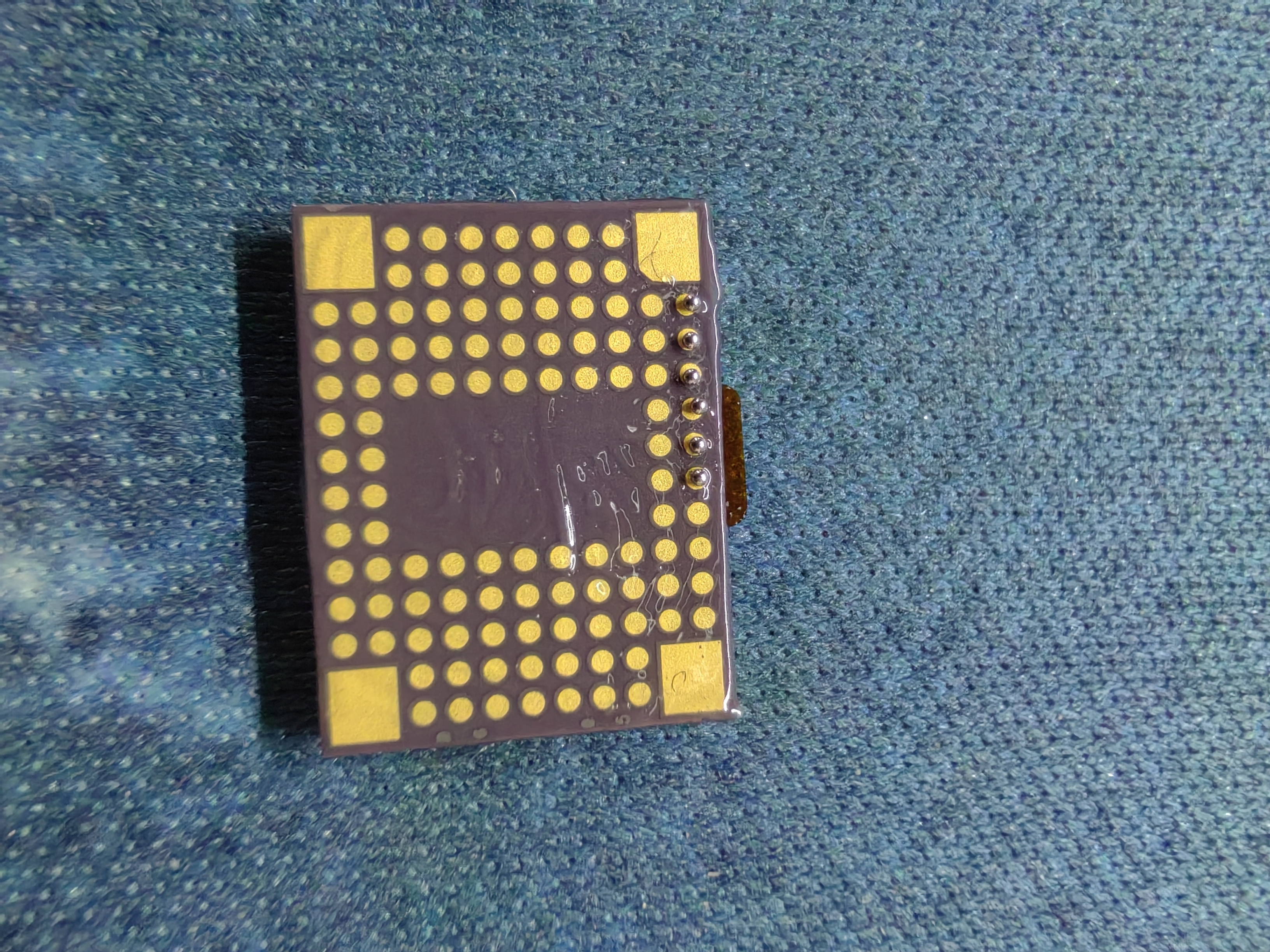
. Manually arranging the balls isn't too difficult, just very troublesome.
Three 0603 47uf capacitors; after powering on, you can use a multimeter to test this capacitor to determine if the LDO output is normal.
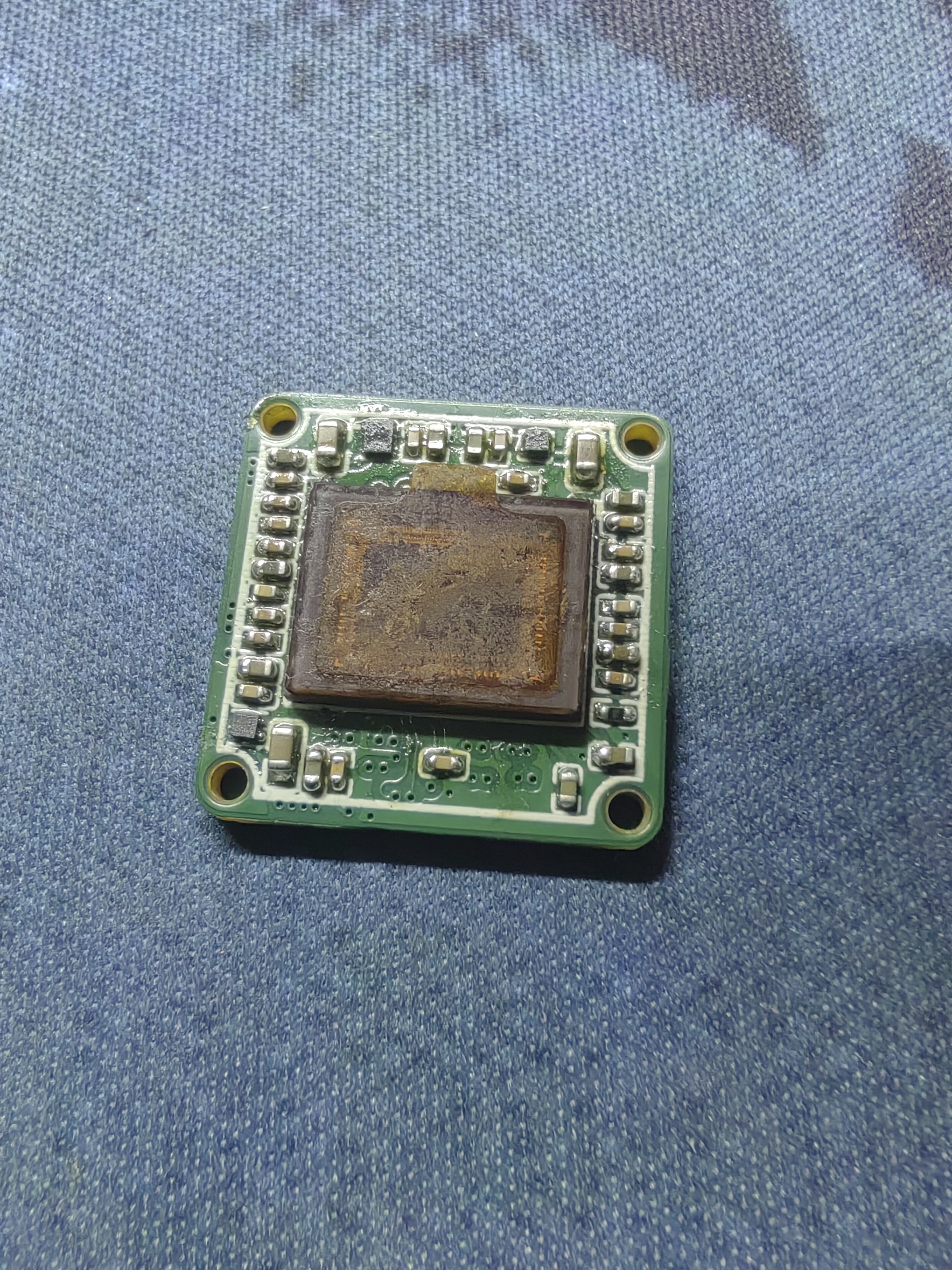
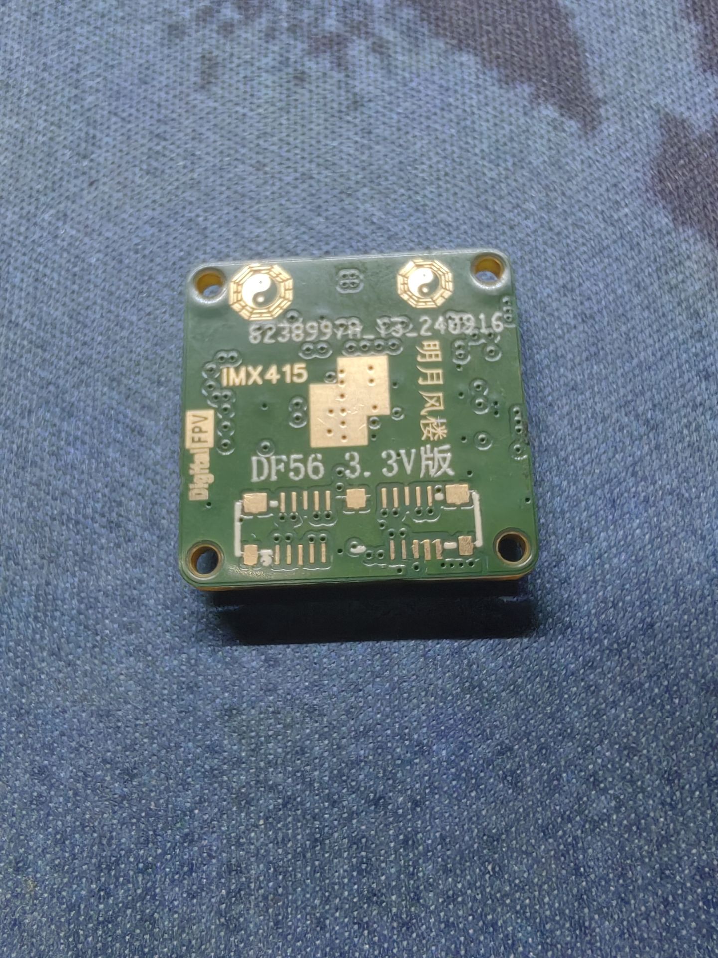
The socket melted a little, but thankfully it's still usable. Hand soldering DF56 is also quite difficult.


BOM_imx415_DigitalFPV.xlsx
IMX415-AAQR-C.PDF
PDF_OPENIPC Image Transmission IMX415 19mm Camera.zip
Altium_OPENIPC Image Transmission IMX415 19mm Camera.zip
PADS_OPENIPC Image Transmission IMX415 19mm Camera.zip
BOM_OPENIPC Image Transmission IMX415 19mm Camera.xlsx
91970
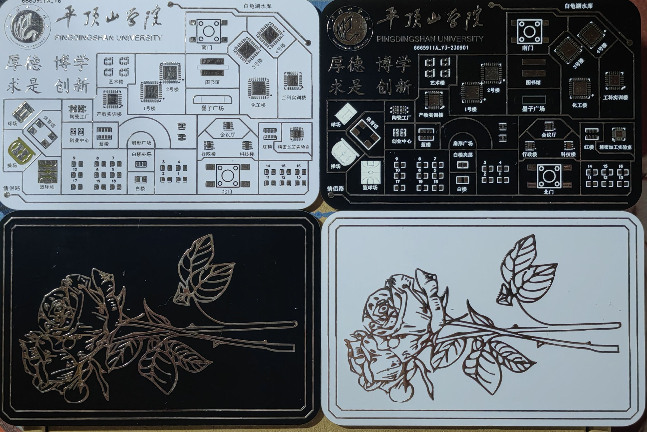
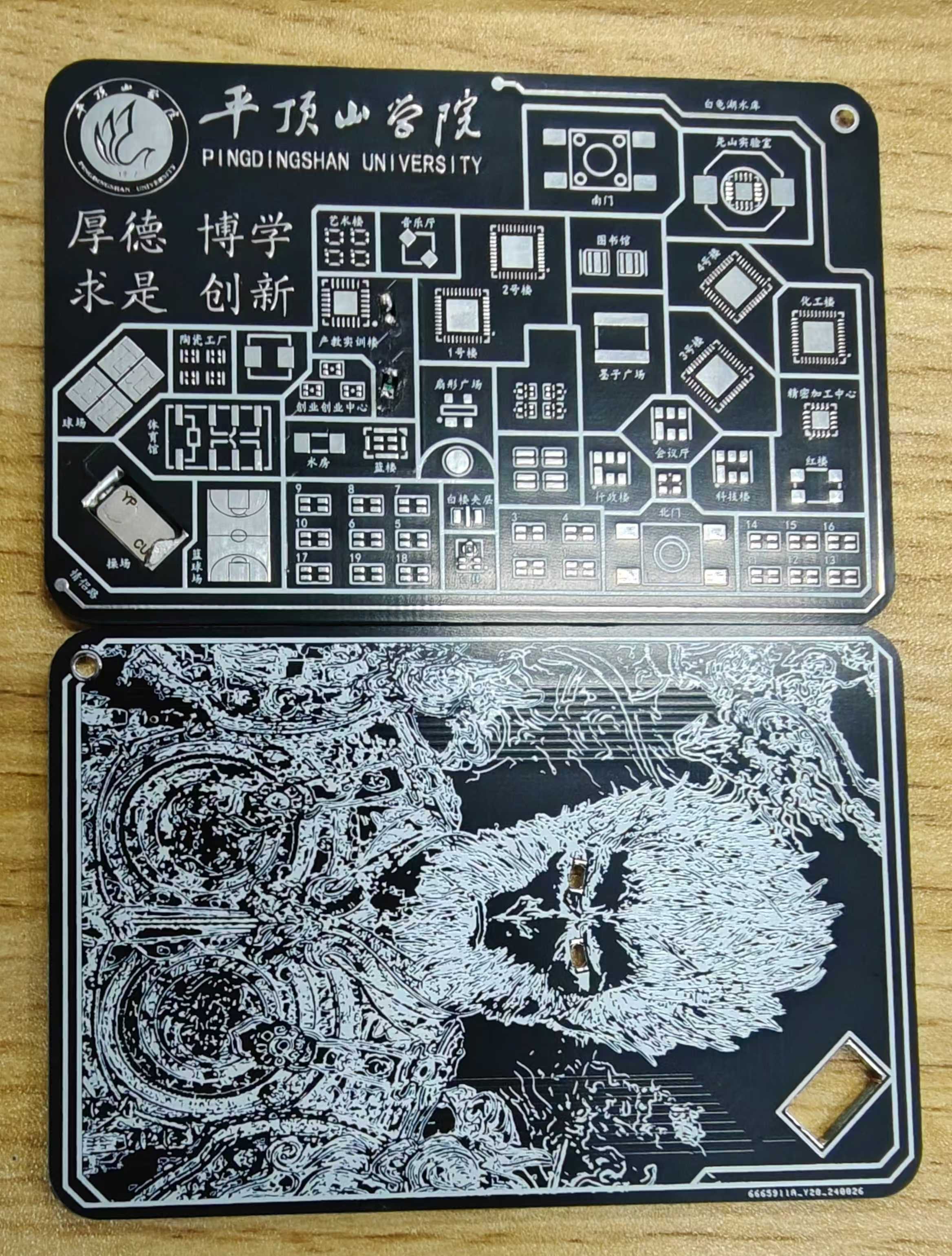
Campus Map + Black Monkey NFC
I saw that other schools had done a very good job, so I made two versions myself. To get a tin surface, you need to add a solder mask layer on top.
The LEDs use surface-mount 0805
chips with a CUID chip
principle: a coil scans the phone, generating alternating current. The two LEDs are connected in parallel (note: the positive and negative terminals of the two LEDs are placed in the same position in the circuit). The two LEDs alternately emit light, which appears to the naked eye as if both are lit. The first board
is 1.2mm or 1.6mm thick
, featuring a school theme and a rose design. The
second board is without NFC, featuring a school theme and a Black Myth: Wukong design. The
third APK is NFC Tools Pro software.
The process is: Task - Add Task - Application - Application - 111 - OK
. [Images: ![26d29ec61938d3a43f6a4296bbcdd63.jpg]
![8ed3fffb68fccb8ee146c8c43cb2993.jpg]]
Gerber_School_Rose.zip
Gerber_school_black_monkey_NFC.zip
2_base.apk
PDF_Campus Map + Black Monkey NFC.zip
Altium_Campus Map + Black Monkey NFC.zip
PADS_Campus Map + Black Monkey NFC.zip
BOM_Campus Map + Black Monkey NFC.xlsx
91971
MSP432P401R Minimum System Board
This project is a minimum system for the TI (Texas Instruments) MSP432P401R microcontroller.
This is a self-made minimum system using a TI (Texas Instruments) MSP432P401R microcontroller. It is programmed with Keil 5, supports ST-T-Link downloading, and most pins are brought out. It has been physically verified.
PDF_msp432p401r Minimum System Board.zip
Altium_msp432p401r Minimum System Board.zip
PADS_msp432p401r Minimum System Board.zip
BOM_msp432p401r Minimum System Board.xlsx
91973
How many calories did Lao Ba eat today?
The webpage featuring hidden easter eggs from the novel "Too Many Loser Heroines" was reproduced using color silkscreen printing.
Official persecution from the production team of "Too Many Noble Female Leads"!
A mysterious girl ate 10 kilograms of carbs but only gained 3 kilograms!
We still don't know how much Lao Ba can actually eat!
Okay, jokes aside, the official website of the "Noble Female Leads" anime provides a special page showing exactly how many carbs Lao Ba ate, which makes you smile and makes you want to replicate it. (Committee Independent Investigation of Hachina Mi Anna Carory Message | TV Anime "Too Many Noble Female Leads!" Official Website (makeine-anime.com), connection speed is relatively slow)
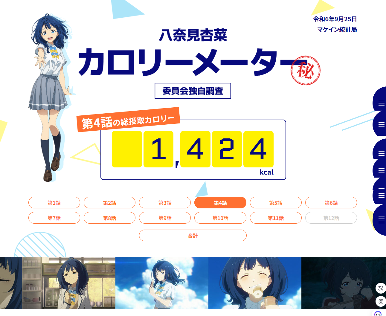
So, color silkscreen + OLED screen is the best combination.
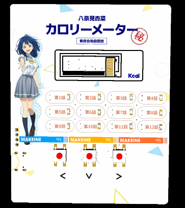

The front of the board has a webpage layout, displaying numbers or other information through a 128x32 OLED screen; orange LEDs indicate the active episode; buttons allow you to select whether a particular episode is included in the statistics.
All control circuitry is concentrated on the back, centered around the ESP32-C3-mini-1 module, including power supply, communication, reset and download, LED driver, and OLED driver.
【About the Replica】
=====Program Description======
Developed using PlatformIO, the OLED uses software I2C driver. It can be easily converted to Arduino code.
The attached code only includes the demo shown in the demonstration video; not all functions are implemented.
Please refer to the circuit diagram for serial port pin definitions. When downloading, you need to press and hold the RST and BOOT buttons, then release RST first, then release BOOT.
Originally, we planned to add serial port settings, Wi-Fi connection, and online data acquisition functions, but since the hardware sample was almost finished and almost all samples were released, we abandoned this plan and directly wrote the data into the program.
=====Circuit Description======
The OLED screen is a 14-pin SSD1306 128x32 module, using the I2C protocol. The peripheral circuitry has high requirements and components cannot be arbitrarily changed.
The orange LED brightness is low; it is recommended to reduce the resistance values of R8~R11.
The LDO is not the 1117; the pin definitions are different. I didn't notice this when designing, which caused me to waste several days buying a new chip.
Only one side of the Type-C connector was used, and the ESP32's USB virtual string recognition failed; I haven't investigated why. Also, the CC cable cannot be used, as it may not provide power.
======Other======
LCSC EDA requires color silkscreen printing to preview the effect; please be sure to select color silkscreen printing when ordering.
To ensure it's not contaminated, please minimize the use of flux and heating elements.
Finally, let's all say: Old Eight has a big stomach, no need for much salt!
Yanami_demo.zip
QQ Video 20240927000628.mp4
PDF_How many calories did Lao Ba eat today? .zip
Altium_LaoBa ate how many calories today? .zip
PADS_How many calories did Lao Ba eat today? .zip
BOM_How many calories did Lao Ba eat today? .xlsx
91983
electronic
 ![IMG_20240926_164627.jpg]
 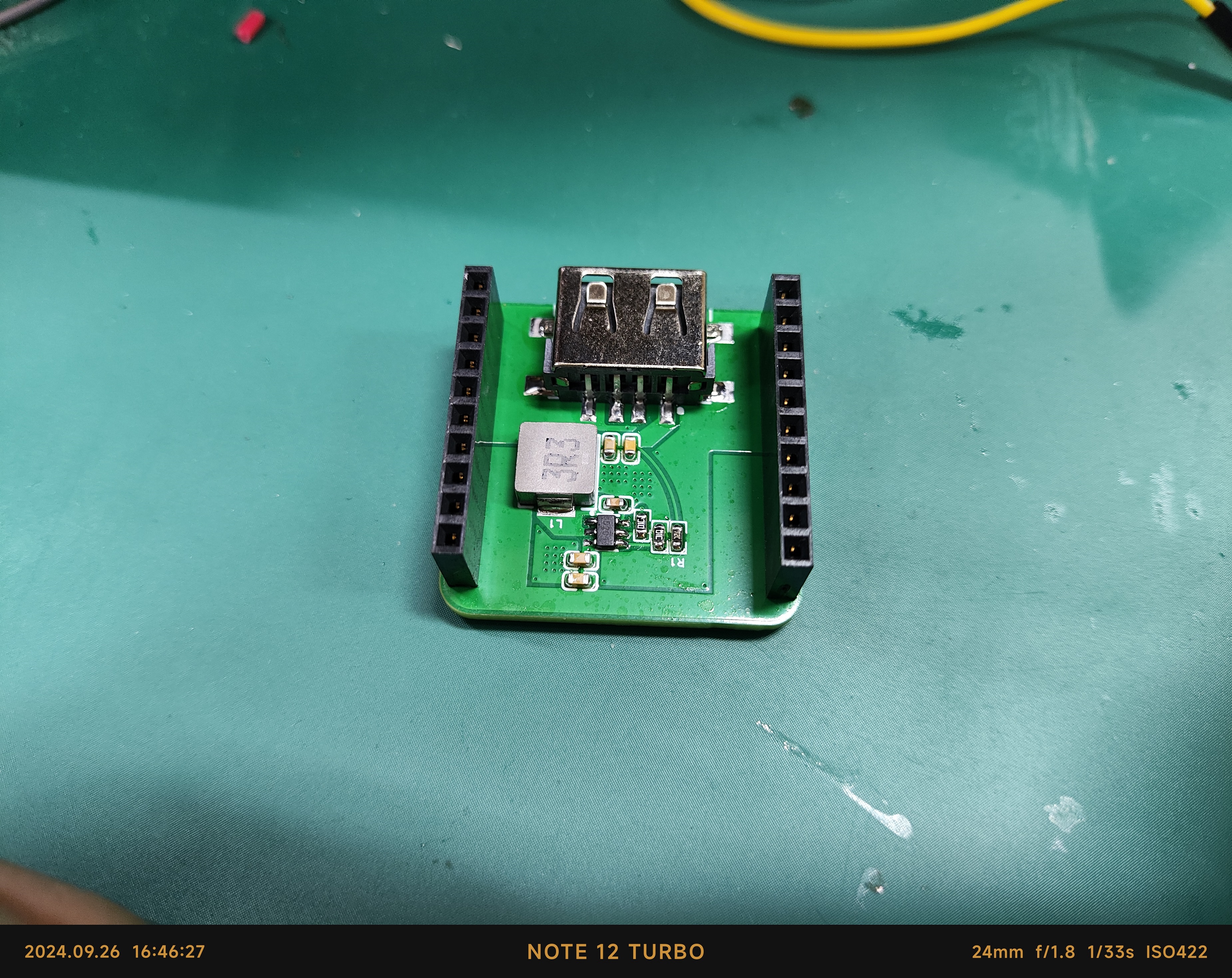 ![IMG_20240926_164642.jpg]]
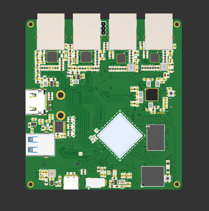
 has two boards in the project
 *In CC mode, the current limit value of CS needs to be adjusted according to the actual application, and the value range is generally 10mR-100mR, with a default value of 10mR.
 : front
  and back
  pin configuration as shown .
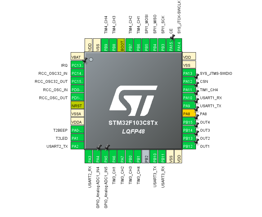


 京公网安备 11010802033920号

 MVKVF2020D-70.000MHZ


